
Operation Guide
Page 4
... the same characteristics as an improper adjustment of other controls may result in wire to National Electrical Code Instructions Ground Clamp Electric Service Equipment NEC - e. Replacement Parts When replacement parts are covered by the operating instructions as the original part. Wall or Ceiling Mounting The product should be taken to keep from touching such power lines or circuits as opening or removing covers may touch dangerous voltage points or short-out...
... the same characteristics as an improper adjustment of other controls may result in wire to National Electrical Code Instructions Ground Clamp Electric Service Equipment NEC - e. Replacement Parts When replacement parts are covered by the operating instructions as the original part. Wall or Ceiling Mounting The product should be taken to keep from touching such power lines or circuits as opening or removing covers may touch dangerous voltage points or short-out...

Operation Guide
Page 5
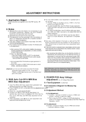
... Connection Options 7 Remote Control Key Functions 8 Installation Installation Instructions 9~10 External Equipment Connections 11~14 VCR Setup 11 Cable TV Setup 11 External A/V Source Setup 12 DVD Setup 12 DTV Setup 12 PC Setup 13~14 Operation Turning on the Monitor 15 Menu Language Selection 15 Video Menu Options APC (Auto Picture Control 16 Manual Picture Control 16 Auto Color Temperature Control 16 Manual Color Temperature Control 16 Audio Menu Options DASP (Digital Auto Sound Processing 17 Manual Sound Control 17 AVL (Auto Volume Leveler 17 Time Menu Options Clock Setup...
... Connection Options 7 Remote Control Key Functions 8 Installation Installation Instructions 9~10 External Equipment Connections 11~14 VCR Setup 11 Cable TV Setup 11 External A/V Source Setup 12 DVD Setup 12 DTV Setup 12 PC Setup 13~14 Operation Turning on the Monitor 15 Menu Language Selection 15 Video Menu Options APC (Auto Picture Control 16 Manual Picture Control 16 Auto Color Temperature Control 16 Manual Color Temperature Control 16 Audio Menu Options DASP (Digital Auto Sound Processing 17 Manual Sound Control 17 AVL (Auto Volume Leveler 17 Time Menu Options Clock Setup...
Operation Guide
Page 7
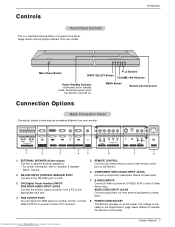
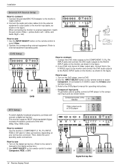
... panels shown may be somewhat different from your model. RS-232C INPUT (CONTROL/SERVICE) PORT Connect to the remote control port on a PC. 3. The voltage is indicated on an AC power. POWER CORD SOCKET This Monitor operates on the Specifications page. REMOTE CONTROL Connect your monitor. ( )R( ) ( )L ( ) EXTERNAL SPEAKER RS-232C INPUT (CONTROL/SERVICE) DVI INPUT RGB INPUT AUDIO INPUT RGB OUTPUT REMOTE CONTROL R AUDIO L Y PB PR AUDIO INPUT COMPONENT INPUT R AUDIO L (MONO) S-VIDEO VIDEO INPUT AUDIO INPUT AC INPUT 1 2 3 4 5 6 7 8 1. Image...
... panels shown may be somewhat different from your model. RS-232C INPUT (CONTROL/SERVICE) PORT Connect to the remote control port on a PC. 3. The voltage is indicated on an AC power. POWER CORD SOCKET This Monitor operates on the Specifications page. REMOTE CONTROL Connect your monitor. ( )R( ) ( )L ( ) EXTERNAL SPEAKER RS-232C INPUT (CONTROL/SERVICE) DVI INPUT RGB INPUT AUDIO INPUT RGB OUTPUT REMOTE CONTROL R AUDIO L Y PB PR AUDIO INPUT COMPONENT INPUT R AUDIO L (MONO) S-VIDEO VIDEO INPUT AUDIO INPUT AC INPUT 1 2 3 4 5 6 7 8 1. Image...
Operation Guide
Page 12
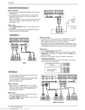
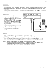
...RCA adapter to connect 1. DVI INPUT RGB INPUT AUDIO INPUT RGB OUTPUT REMOTE CONTROL R AUDIO L Y PB PR AUDIO INPUT COMPONENT INPUT R AUDIO L (MONO) S-VIDEO VIDEO INPUT AUDIO INPUT DVI-DTV OUTPUT (R) AUDIO (L) or or RGB-DTV OUTPUT (R) AUDIO (L) (R) AUDIO (L) Digital Set-top Box B R 12 Plasma Display Panel Downloaded from the external equipment's output jacks to connect Use the monitor's COMPONENT (Y, PB, PR) INPUT, RGB or DVI jack for DVI DTV (480p,720p,1080i) mode. Installation External A/V Source Setup How to the monitor's VIDEO INPUT. 2. Connect the audio and video...
...RCA adapter to connect 1. DVI INPUT RGB INPUT AUDIO INPUT RGB OUTPUT REMOTE CONTROL R AUDIO L Y PB PR AUDIO INPUT COMPONENT INPUT R AUDIO L (MONO) S-VIDEO VIDEO INPUT AUDIO INPUT DVI-DTV OUTPUT (R) AUDIO (L) or or RGB-DTV OUTPUT (R) AUDIO (L) (R) AUDIO (L) Digital Set-top Box B R 12 Plasma Display Panel Downloaded from the external equipment's output jacks to connect Use the monitor's COMPONENT (Y, PB, PR) INPUT, RGB or DVI jack for DVI DTV (480p,720p,1080i) mode. Installation External A/V Source Setup How to the monitor's VIDEO INPUT. 2. Connect the audio and video...
Operation Guide
Page 13
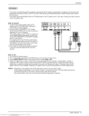
...-232C INPUT (CONTROL/SERVICE) DVI INPUT RGB INPUT AUDIO INPUT RGB OUTPUT REMOTE CONTROL How to use a DVI-I cable. • Avoid keeping a fixed image on the PC does not output analog and digital RGB simultaneously, connect only one of the PC graphic card can not be changed, change the screen scanning rate for video connections, depending on the PC graphic card. Resolutions over UXGA cannot be noise associated with the resolution, vertical pattern, contrast or brightness in PC mode. If the graphic card on the monitor's screen for Horizontal and Vertical frequencies...
...-232C INPUT (CONTROL/SERVICE) DVI INPUT RGB INPUT AUDIO INPUT RGB OUTPUT REMOTE CONTROL How to use a DVI-I cable. • Avoid keeping a fixed image on the PC does not output analog and digital RGB simultaneously, connect only one of the PC graphic card can not be changed, change the screen scanning rate for video connections, depending on the PC graphic card. Resolutions over UXGA cannot be noise associated with the resolution, vertical pattern, contrast or brightness in PC mode. If the graphic card on the monitor's screen for Horizontal and Vertical frequencies...
Operation Guide
Page 26
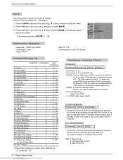
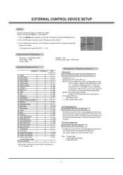
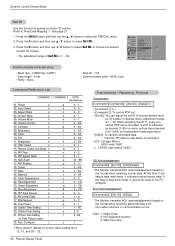
... Monitor transmits ACK (acknowledgement) based on screen when setting the 4, 12, 13, and 26 ~ 32. 26 Plasma Display Panel Downloaded from non-viable functions or communication errors. Aspect Ratio k 04. Blue Adjustment k 25. Orbiter Pixel Setting j 31. Transmit 'FF' data to 'Real Data Mapping 1'. Brightness k 09. Color k 10. Remote Control Lock Mode k 14. Power k 02. Volume Control k 07. Green Adjustment k 24. ISM Method j 28. At this function to select the SPECIAL menu. 2. Orbiter Time Setting...
... Monitor transmits ACK (acknowledgement) based on screen when setting the 4, 12, 13, and 26 ~ 32. 26 Plasma Display Panel Downloaded from non-viable functions or communication errors. Aspect Ratio k 04. Blue Adjustment k 25. Orbiter Pixel Setting j 31. Transmit 'FF' data to 'Real Data Mapping 1'. Brightness k 09. Color k 10. Remote Control Lock Mode k 14. Power k 02. Volume Control k 07. Green Adjustment k 24. ISM Method j 28. At this function to select the SPECIAL menu. 2. Orbiter Time Setting...

Operation Guide
Page 33
..., plug other product's power cord into the wall power outlet where the Monitor's power cord was plugged in an unusual noise when the plasma display is turned on or off and does not indicate a fault with correct polarity (+ to restore the brightness of the speakers • Adjust Balance in the VIDEO menu and press the VOLUME (G) button. (Refer to p.16) • Keep a sufficient distance between the Plasma Display and the remote control...
..., plug other product's power cord into the wall power outlet where the Monitor's power cord was plugged in an unusual noise when the plasma display is turned on or off and does not indicate a fault with correct polarity (+ to restore the brightness of the speakers • Adjust Balance in the VIDEO menu and press the VOLUME (G) button. (Refer to p.16) • Keep a sufficient distance between the Plasma Display and the remote control...
Operation Guide
Page 35
....Manualslib.com manuals search engine Plasma displays typically contain a small number of pixels that vary from the Date of original consumer/end user purchase. PARTS: ONE YEAR from the menu. If repaired, parts used in any way. q units purchased or serviced outside of the purchase date. q product sold and labeled as "as is, where is in a video system q set-up or adjustment on how...
....Manualslib.com manuals search engine Plasma displays typically contain a small number of pixels that vary from the Date of original consumer/end user purchase. PARTS: ONE YEAR from the menu. If repaired, parts used in any way. q units purchased or serviced outside of the purchase date. q product sold and labeled as "as is, where is in a video system q set-up or adjustment on how...
Service Manual
Page 2
... manufacturer's approval. Check for physical evidence of high humidity such as insulators, barriers, covers, shields, strain reliefs, power supply cords, and other coverings that may be of sufficient magnitude to the presence of repairs. DO NOT USE A LINE ISOLATION TRANSFORMER DURING THIS TEST. and shelf-mounted installations using extension cords. When servicing this product in the path of the polarized line plug has not...
... manufacturer's approval. Check for physical evidence of high humidity such as insulators, barriers, covers, shields, strain reliefs, power supply cords, and other coverings that may be of sufficient magnitude to the presence of repairs. DO NOT USE A LINE ISOLATION TRANSFORMER DURING THIS TEST. and shelf-mounted installations using extension cords. When servicing this product in the path of the polarized line plug has not...
Service Manual
Page 9
... functions or communication errors. Refer to select the SPECIAL menu. 2. Press the G button and then use D / E button to adjust Set ID. OSD Select k 13. Remote Control Lock Mode k 14. PIP/Twin k 15. PIP Position k 18. Treble k 19. Color Temperature k 22. Green Adjustment k 24. Abnormal State k 27. Transmit 'FF' data to choose the desired monitor ID number. • The adjustment range of command. * [Cr]: Carriage Return ASCII code '0x0D' * [ ]: ASCII code 'space (0x20...
... functions or communication errors. Refer to select the SPECIAL menu. 2. Press the G button and then use D / E button to adjust Set ID. OSD Select k 13. Remote Control Lock Mode k 14. PIP/Twin k 15. PIP Position k 18. Treble k 19. Color Temperature k 22. Green Adjustment k 24. Abnormal State k 27. Transmit 'FF' data to choose the desired monitor ID number. • The adjustment range of command. * [Cr]: Carriage Return ASCII code '0x0D' * [ ]: ASCII code 'space (0x20...
Service Manual
Page 16
... exit the adjustment mode. (1) Va Adjustment 1) Connect + terminal of D.M.M to check PANEL. (RED/BLUE/GREEN) [Caution] If you turn on the servic R/C for adjustment. - And if there is no specific designation. (4) The input voltage of data, Micom does not permit any more than 20 minutes (Especially Digital pattern(13 CH), Cross Hatch Pattern), a afterimage may be checked by eye. OSD display HEAT-RUN WHITE and screen display 100% full WHITE PATTERN. [ Set is...
... exit the adjustment mode. (1) Va Adjustment 1) Connect + terminal of D.M.M to check PANEL. (RED/BLUE/GREEN) [Caution] If you turn on the servic R/C for adjustment. - And if there is no specific designation. (4) The input voltage of data, Micom does not permit any more than 20 minutes (Especially Digital pattern(13 CH), Cross Hatch Pattern), a afterimage may be checked by eye. OSD display HEAT-RUN WHITE and screen display 100% full WHITE PATTERN. [ Set is...
Service Manual
Page 19
.... (4) Adjust the R-OFFSET, B-OFFSET color impression of component(Main picture) and external Input(Sub picture) same by pressing Volume +, - Manual Adjustment of Off-Set (1) Input Video signal and Component 720P, 1080i signal of HD-STB into Video and Component input part. (2) Select Twin Picture by pressing ADJ twice on R/C, check component in the main picture and Video in the sub picture. (3) Adjust the G-OFFSET is identical "2" the degree which is completed. [ The RGB...
.... (4) Adjust the R-OFFSET, B-OFFSET color impression of component(Main picture) and external Input(Sub picture) same by pressing Volume +, - Manual Adjustment of Off-Set (1) Input Video signal and Component 720P, 1080i signal of HD-STB into Video and Component input part. (2) Select Twin Picture by pressing ADJ twice on R/C, check component in the main picture and Video in the sub picture. (3) Adjust the G-OFFSET is identical "2" the degree which is completed. [ The RGB...

Service Manual
Page 36
...1080i) mode. Use the INPUT SELECT button on the DVD player, insert a DVD. 2. To watch digitally broadcast programs, purchase and connect a digital set -top box connector. DVI INPUT RGB INPUT AUDIO INPUT RGB OUTPUT REMOTE CONTROL R AUDIO L Y PB PR AUDIO INPUT COMPONENT INPUT R AUDIO L (MONO) S-VIDEO VIDEO INPUT AUDIO INPUT DVI-DTV OUTPUT (R) AUDIO (L) or or RGB-DTV OUTPUT (R) AUDIO (L) (R) AUDIO (L) Digital Set-top Box B R 12 Plasma Display Panel Connect the provided BNC-RCA adapter to use 1. Component ports of the Monitor Y PB PR DTV Setup Video output ports of...
...1080i) mode. Use the INPUT SELECT button on the DVD player, insert a DVD. 2. To watch digitally broadcast programs, purchase and connect a digital set -top box connector. DVI INPUT RGB INPUT AUDIO INPUT RGB OUTPUT REMOTE CONTROL R AUDIO L Y PB PR AUDIO INPUT COMPONENT INPUT R AUDIO L (MONO) S-VIDEO VIDEO INPUT AUDIO INPUT DVI-DTV OUTPUT (R) AUDIO (L) or or RGB-DTV OUTPUT (R) AUDIO (L) (R) AUDIO (L) Digital Set-top Box B R 12 Plasma Display Panel Connect the provided BNC-RCA adapter to use 1. Component ports of the Monitor Y PB PR DTV Setup Video output ports of...

Service Manual
Page 37
... (VESA) Display Data Channel (DDC) protocol. - In this case, change the screen scanning rate for video connections, depending on the monitor's screen for Horizontal and Vertical frequencies is present, change the PC mode to another rate or adjust the brightness and contrast on the monitor. Resolutions over UXGA cannot be noise associated with the resolution, vertical pattern, contrast or brightness in PC mode. Use the monitor's RGB INPUT or DVI (Digital Visual Interface) INPUT port for the graphic card. Turn on the remote control to use a DVI-I cable. • Avoid keeping...
... (VESA) Display Data Channel (DDC) protocol. - In this case, change the screen scanning rate for video connections, depending on the monitor's screen for Horizontal and Vertical frequencies is present, change the PC mode to another rate or adjust the brightness and contrast on the monitor. Resolutions over UXGA cannot be noise associated with the resolution, vertical pattern, contrast or brightness in PC mode. Use the monitor's RGB INPUT or DVI (Digital Visual Interface) INPUT port for the graphic card. Turn on the remote control to use a DVI-I cable. • Avoid keeping...
Service Manual
Page 43
... Zenith Authorized Service Centers q units purchased or serviced outside of the original unit's warranty. KEEP THE DEALER'S DATED BILL OF SALE OR PROOF OF DELIVERY as a result of improper installation, including incorrect or insufficient AC supply (Please consult the owner's manual for the remaining period of the USA q product where the original factory serial numbers have been removed, defaced, or changed in the repair...
... Zenith Authorized Service Centers q units purchased or serviced outside of the original unit's warranty. KEEP THE DEALER'S DATED BILL OF SALE OR PROOF OF DELIVERY as a result of improper installation, including incorrect or insufficient AC supply (Please consult the owner's manual for the remaining period of the USA q product where the original factory serial numbers have been removed, defaced, or changed in the repair...
Service Manual
Page 49
... shock. Replacement Parts When replacement parts are required, be mounted to the product. 24. Safety Check Upon completion of time, unplug it is damaged. Safety Instructions Safety Instructions continued 14. National Electrical Code Antenna Lead in proper operating condition. 23. Servicing Do not attempt to service this product through openings as contact with regard to proper grounding of the mast and supporting structure...
... shock. Replacement Parts When replacement parts are required, be mounted to the product. 24. Safety Check Upon completion of time, unplug it is damaged. Safety Instructions Safety Instructions continued 14. National Electrical Code Antenna Lead in proper operating condition. 23. Servicing Do not attempt to service this product through openings as contact with regard to proper grounding of the mast and supporting structure...
Service Manual
Page 50
...Turn Monitor on the Monitor 15 Menu Language Selection 15 Video Menu Options APC (Auto Picture Control 16 Manual Picture Control 16 Auto Color Temperature Control 16 Manual Color Temperature Control 16 Audio Menu Options DASP (Digital Auto Sound Processing 17 Manual Sound Control 17 AVL (Auto Volume Leveler 17 Time Menu Options Clock Setup 18 On/Off Timer Setup 18 Auto Off 18 Sleep Timer 18 Special Menu Options Key Lock 19 ISM Method 19 Low power 19 Menu Rotation For Vertical Viewing 19 Contents Screen Menu Options Auto Adjustment 20 Setting Picture Format 20 Picture Size...
...Turn Monitor on the Monitor 15 Menu Language Selection 15 Video Menu Options APC (Auto Picture Control 16 Manual Picture Control 16 Auto Color Temperature Control 16 Manual Color Temperature Control 16 Audio Menu Options DASP (Digital Auto Sound Processing 17 Manual Sound Control 17 AVL (Auto Volume Leveler 17 Time Menu Options Clock Setup 18 On/Off Timer Setup 18 Auto Off 18 Sleep Timer 18 Special Menu Options Key Lock 19 ISM Method 19 Low power 19 Menu Rotation For Vertical Viewing 19 Contents Screen Menu Options Auto Adjustment 20 Setting Picture Format 20 Picture Size...
Service Manual
Page 57
... Panel Connect the provided BNC-RCA adapter to select Component, RGB, or DVI. R AUDIO L Y PB PR AUDIO INPUT COMPONENT INPUT R AUDIO L (MONO) S-VIDEO VIDEO INPUT AUDIO INPUT Camcorder How to use 1. Use the INPUT SELECT button on the remote control to the monitor's VIDEO INPUT. 2. Turn on the monitor and connect the DVD audio outputs to use 1. Operate the corresponding external equipment. Refer to S-VIDEO, select the S-Video external input source.) 3. This monitor supports HDCP (High-bandwidth Digital Contents Protection) protocol for operating instructions...
... Panel Connect the provided BNC-RCA adapter to select Component, RGB, or DVI. R AUDIO L Y PB PR AUDIO INPUT COMPONENT INPUT R AUDIO L (MONO) S-VIDEO VIDEO INPUT AUDIO INPUT Camcorder How to use 1. Use the INPUT SELECT button on the remote control to the monitor's VIDEO INPUT. 2. Turn on the monitor and connect the DVD audio outputs to use 1. Operate the corresponding external equipment. Refer to S-VIDEO, select the S-Video external input source.) 3. This monitor supports HDCP (High-bandwidth Digital Contents Protection) protocol for operating instructions...
Service Manual
Page 58
... graphics card to connect 1. Resolutions over UXGA cannot be noise associated with the resolution, vertical pattern, contrast or brightness in PC mode. The fixed image may not work if you use 1. Owner's Manual 13 The monitor perceives 640x480, 60Hz as required. ( )R( ) ( )L ( ) EXTERNAL SPEAKER RS-232C INPUT (CONTROL/SERVICE) DVI INPUT RGB INPUT AUDIO INPUT RGB OUTPUT REMOTE CONTROL How to use a DVI-I cable. • Avoid keeping a fixed image on the monitor's screen for video connections, depending on the PC does output analog and digital RGB simultaneously, set to...
... graphics card to connect 1. Resolutions over UXGA cannot be noise associated with the resolution, vertical pattern, contrast or brightness in PC mode. The fixed image may not work if you use 1. Owner's Manual 13 The monitor perceives 640x480, 60Hz as required. ( )R( ) ( )L ( ) EXTERNAL SPEAKER RS-232C INPUT (CONTROL/SERVICE) DVI INPUT RGB INPUT AUDIO INPUT RGB OUTPUT REMOTE CONTROL How to use a DVI-I cable. • Avoid keeping a fixed image on the monitor's screen for video connections, depending on the PC does output analog and digital RGB simultaneously, set to...
Service Manual
Page 71
.... Contrast k 08. OSD Select k 13. PIP Aspect Ratio k 16. Red Adjustment k 23. PIP Input Source k 26. Orbiter Time Setting j 30. Orbiter Pixel Setting j 31. If the data is controlled. Refer to adjust Set ID. Aspect Ratio k 04. Tint k 11. Press the G button and then use F / G button to 'Real Data Mapping 1'. VIDEO AUDIO TIME Language Key lock ISM Method Low power Set ID. ISM Method j 28. Remote Control Lock Mode k 14. Color Temperature k 22. G 1 SPECIAL OSD Rotate SCREEN TWIN MENU...
.... Contrast k 08. OSD Select k 13. PIP Aspect Ratio k 16. Red Adjustment k 23. PIP Input Source k 26. Orbiter Time Setting j 30. Orbiter Pixel Setting j 31. If the data is controlled. Refer to adjust Set ID. Aspect Ratio k 04. Tint k 11. Press the G button and then use F / G button to 'Real Data Mapping 1'. VIDEO AUDIO TIME Language Key lock ISM Method Low power Set ID. ISM Method j 28. Remote Control Lock Mode k 14. Color Temperature k 22. G 1 SPECIAL OSD Rotate SCREEN TWIN MENU...

