

Owner's Manual
Page 5
.../recorder 20 Connecting a digital satellite tuner or a cable TV tuner 21 Connecting a digital airwave tuner 22 Connecting a VCR 23 Connecting other external components 24 Connecting a subwoofer 25 Connecting the AC power supply cable 26 SETUP Getting started 27 Installing batteries in the remote control 27 Operation range of the remote control...
.../recorder 20 Connecting a digital satellite tuner or a cable TV tuner 21 Connecting a digital airwave tuner 22 Connecting a VCR 23 Connecting other external components 24 Connecting a subwoofer 25 Connecting the AC power supply cable 26 SETUP Getting started 27 Installing batteries in the remote control 27 Operation range of the remote control...

Owner's Manual
Page 13
... SYSTEM OPTICAL COAXIAL CONNECTOR DIGITAL INPUT Controls and functions B 1 23 OUT DVD IN AUX HDMI 45 67 89 0 A L R VCR TV/STB SUBWOOFER VIDEO AUDIO INPUT OUT TV/STB AUX DVD SYSTEM OPTICAL COAXIAL CONNECTOR DIGITAL INPUT 1 HDMI OUT jack Connect to the HDMI input jack on your...HDMI component such as a TV or a projector connected to this unit (see page 25). English 9 En A SYSTEM CONNECTOR jack Use to connect a Yamaha subwoofer equipped with a SYSTEM CONNECTOR jack to display the OSD of this unit (see page 19). 8 TV/STB OPTICAL DIGITAL INPUT jack Connect your TV, ...
... SYSTEM OPTICAL COAXIAL CONNECTOR DIGITAL INPUT Controls and functions B 1 23 OUT DVD IN AUX HDMI 45 67 89 0 A L R VCR TV/STB SUBWOOFER VIDEO AUDIO INPUT OUT TV/STB AUX DVD SYSTEM OPTICAL COAXIAL CONNECTOR DIGITAL INPUT 1 HDMI OUT jack Connect to the HDMI input jack on your...HDMI component such as a TV or a projector connected to this unit (see page 25). English 9 En A SYSTEM CONNECTOR jack Use to connect a Yamaha subwoofer equipped with a SYSTEM CONNECTOR jack to display the OSD of this unit (see page 19). 8 TV/STB OPTICAL DIGITAL INPUT jack Connect your TV, ...

Owner's Manual
Page 20
... satellite tuner, cable TV tuner, digital air wave tuner, and game console. Audio connection Video connection TV This unit DVD player 16 En Subwoofer Digital satellite tuner or cable TV tuner VCR or game console For details on how to connect various types of analog input jacks For audio.../video input • 2 HDMI input jacks For audio output • 1 subwoofer output jack For audio/video output • 1 HDMI output jack For video output • 1 analog output jack Use these jacks/terminal to 26. ...
... satellite tuner, cable TV tuner, digital air wave tuner, and game console. Audio connection Video connection TV This unit DVD player 16 En Subwoofer Digital satellite tuner or cable TV tuner VCR or game console For details on how to connect various types of analog input jacks For audio.../video input • 2 HDMI input jacks For audio output • 1 subwoofer output jack For audio/video output • 1 HDMI output jack For video output • 1 analog output jack Use these jacks/terminal to 26. ...

Owner's Manual
Page 21
... for connections Audio/Video A HDMI cable Audio Audio pin cable (supplied) (White) (Red) Optical cable (supplied) (White) (Red) Digital audio pin cable (supplied) (Orange) (Orange) Subwoofer pin cable 5 System connector cable Video OSD video pin cable (supplied) (Yellow) (Yellow) ■ Information on HDMI™ Audio signals Input source Audio signal type...
... for connections Audio/Video A HDMI cable Audio Audio pin cable (supplied) (White) (Red) Optical cable (supplied) (White) (Red) Digital audio pin cable (supplied) (Orange) (Orange) Subwoofer pin cable 5 System connector cable Video OSD video pin cable (supplied) (Yellow) (Yellow) ■ Information on HDMI™ Audio signals Input source Audio signal type...

Owner's Manual
Page 22
... digital output jack on your TV to the TV/STB OPTICAL DIGITAL IN jack on this unit OUT DVD IN AUX HDMI L R VCR TV/STB SUBWOOFER VIDEO AUDIO INPUT OUT TV/STB AUX OPTICAL DVD SYSTEM COAXIAL CONNECTOR DIGITAL INPUT * This connection (except for simpler and easier connections, and you secure...
... digital output jack on your TV to the TV/STB OPTICAL DIGITAL IN jack on this unit OUT DVD IN AUX HDMI L R VCR TV/STB SUBWOOFER VIDEO AUDIO INPUT OUT TV/STB AUX OPTICAL DVD SYSTEM COAXIAL CONNECTOR DIGITAL INPUT * This connection (except for simpler and easier connections, and you secure...

Owner's Manual
Page 23
... digital output jack, connect the optical digital output jack on your TV to the TV/STB AUDIO INPUT jacks on this unit L R VCR TV/STB SUBWOOFER VIDEO AUDIO INPUT OUT TV/STB AUX OPTICAL DVD SYSTEM COAXIAL CONNECTOR DIGITAL INPUT PREPARATION R L Analog audio output Video input Optical digital output Video OSD...
... digital output jack, connect the optical digital output jack on your TV to the TV/STB AUDIO INPUT jacks on this unit L R VCR TV/STB SUBWOOFER VIDEO AUDIO INPUT OUT TV/STB AUX OPTICAL DVD SYSTEM COAXIAL CONNECTOR DIGITAL INPUT PREPARATION R L Analog audio output Video input Optical digital output Video OSD...

Owner's Manual
Page 24
..., connect the analog audio output jacks on your DVD/VCR combo player/recorder to the VCR AUDIO INPUT jacks on this unit L R VCR TV/STB SUBWOOFER VIDEO AUDIO INPUT OUT TV/STB AUX OPTICAL DVD SYSTEM COAXIAL CONNECTOR DIGITAL INPUT * For the DVD/VCR combo player/recorder connection R L Analog audio output...
..., connect the analog audio output jacks on your DVD/VCR combo player/recorder to the VCR AUDIO INPUT jacks on this unit L R VCR TV/STB SUBWOOFER VIDEO AUDIO INPUT OUT TV/STB AUX OPTICAL DVD SYSTEM COAXIAL CONNECTOR DIGITAL INPUT * For the DVD/VCR combo player/recorder connection R L Analog audio output...

Owner's Manual
Page 25
... is not necessary if your TV has a built-in digital satellite tuner or cable TV tuner (see "Connecting a TV" on this unit L R VCR TV/STB SUBWOOFER VIDEO AUDIO INPUT OUT TV/STB AUX OPTICAL DVD SYSTEM COAXIAL CONNECTOR DIGITAL INPUT PREPARATION R L Analog audio output Optical digital output Video signal to the...
... is not necessary if your TV has a built-in digital satellite tuner or cable TV tuner (see "Connecting a TV" on this unit L R VCR TV/STB SUBWOOFER VIDEO AUDIO INPUT OUT TV/STB AUX OPTICAL DVD SYSTEM COAXIAL CONNECTOR DIGITAL INPUT PREPARATION R L Analog audio output Optical digital output Video signal to the...

Owner's Manual
Page 26
... to the analog audio output jacks on your digital airwave tuner to the TV/STB OPTICAL DIGITAL INPUT jack on this unit L R VCR TV/STB SUBWOOFER VIDEO AUDIO INPUT OUT TV/STB AUX OPTICAL DVD SYSTEM COAXIAL CONNECTOR DIGITAL INPUT Connect to the TV 22 En Connect the optical digital output...
... to the analog audio output jacks on your digital airwave tuner to the TV/STB OPTICAL DIGITAL INPUT jack on this unit L R VCR TV/STB SUBWOOFER VIDEO AUDIO INPUT OUT TV/STB AUX OPTICAL DVD SYSTEM COAXIAL CONNECTOR DIGITAL INPUT Connect to the TV 22 En Connect the optical digital output...

Owner's Manual
Page 27
Connect red plugs to the right jacks and white plugs to the TV English 23 En Rear panel of this unit. PREPARATION Connections Connecting a VCR To connect a VCR, connect the analog audio output jacks on your VCR to the VCR AUDIO INPUT jacks on this unit L R VCR TV/STB SUBWOOFER VIDEO AUDIO INPUT OUT TV/STB AUX OPTICAL DVD SYSTEM COAXIAL CONNECTOR DIGITAL INPUT R L Analog audio output Audio Audio pin cable VCR Video signal to the left jacks.
Connect red plugs to the right jacks and white plugs to the TV English 23 En Rear panel of this unit. PREPARATION Connections Connecting a VCR To connect a VCR, connect the analog audio output jacks on your VCR to the VCR AUDIO INPUT jacks on this unit L R VCR TV/STB SUBWOOFER VIDEO AUDIO INPUT OUT TV/STB AUX OPTICAL DVD SYSTEM COAXIAL CONNECTOR DIGITAL INPUT R L Analog audio output Audio Audio pin cable VCR Video signal to the left jacks.

Owner's Manual
Page 28
Optical cable Audio 24 En Connections Connecting other external components If your component supports optical digital connections, connect the optical digital output jack on your component (e.g., DVD player/recorder) to the AUX OPTICAL DIGITAL INPUT jack on this unit L R VCR TV/STB SUBWOOFER VIDEO AUDIO INPUT OUT TV/STB AUX OPTICAL DVD SYSTEM COAXIAL CONNECTOR DIGITAL INPUT Optical digital output Video signal to the TV DVD player/recorder, game console, CD player, etc. Rear panel of this unit.
Optical cable Audio 24 En Connections Connecting other external components If your component supports optical digital connections, connect the optical digital output jack on your component (e.g., DVD player/recorder) to the AUX OPTICAL DIGITAL INPUT jack on this unit L R VCR TV/STB SUBWOOFER VIDEO AUDIO INPUT OUT TV/STB AUX OPTICAL DVD SYSTEM COAXIAL CONNECTOR DIGITAL INPUT Optical digital output Video signal to the TV DVD player/recorder, game console, CD player, etc. Rear panel of this unit.

Owner's Manual
Page 29
...Yamaha subwoofer equipped with a SYSTEM CONNECTOR terminal, connect it to the SUBWOOFER jack on this unit controls the power mode of the subwoofer. Rear panel of this unit. If the subwoofer is connected using a system type connection, changing the power mode of this unit. This connection alone does not output sound from the connected subwoofer...CONNECTOR Audio Subwoofer pin cable 5 System connector cable Subwoofer 25 En English To output sound from the connected subwoofer. PREPARATION Connections Connecting a subwoofer Connect the monaural input jack on your subwoofer and ...
...Yamaha subwoofer equipped with a SYSTEM CONNECTOR terminal, connect it to the SUBWOOFER jack on this unit controls the power mode of the subwoofer. Rear panel of this unit. If the subwoofer is connected using a system type connection, changing the power mode of this unit. This connection alone does not output sound from the connected subwoofer...CONNECTOR Audio Subwoofer pin cable 5 System connector cable Subwoofer 25 En English To output sound from the connected subwoofer. PREPARATION Connections Connecting a subwoofer Connect the monaural input jack on your subwoofer and ...

Owner's Manual
Page 36
... if SOUND OPTIMZ only is selected. *2 The sound optimization procedure is skipped if BEAM OPTIMZ only is selected. *3 The subwoofer checking procedure is skipped if BEAM OPTIMZ only is selected. *2 *3 Checking the subwoofer and optimizing the beam delay, frequency, and volume Sound optimization 32 En This unit employs the beam optimization and...
... if SOUND OPTIMZ only is selected. *2 The sound optimization procedure is skipped if BEAM OPTIMZ only is selected. *3 The subwoofer checking procedure is skipped if BEAM OPTIMZ only is selected. *2 *3 Checking the subwoofer and optimizing the beam delay, frequency, and volume Sound optimization 32 En This unit employs the beam optimization and...

Owner's Manual
Page 37
...and balance the sound beam output levels using MANUAL SETUP (see page 58) once the AUTO SETUP procedure is completed. • If a subwoofer with the walls will be when you are no large obstacles between 10 and 12 o'clock as viewed on a conventional clockface and set VOLUME... position. Do not place the IntelliBeam microphone more than 1 m (3.3 ft) upper or lower from the center of this unit. - MIN MAX MIN MAX Subwoofer 1 Press STANDBY/ON to the INTELLIBEAM MIC jack on the front panel. 3 Place the IntelliBeam microphone on a flat level surface more than 1.8 m (6.0 ft...
...and balance the sound beam output levels using MANUAL SETUP (see page 58) once the AUTO SETUP procedure is completed. • If a subwoofer with the walls will be when you are no large obstacles between 10 and 12 o'clock as viewed on a conventional clockface and set VOLUME... position. Do not place the IntelliBeam microphone more than 1 m (3.3 ft) upper or lower from the center of this unit. - MIN MAX MIN MAX Subwoofer 1 Press STANDBY/ON to the INTELLIBEAM MIC jack on the front panel. 3 Place the IntelliBeam microphone on a flat level surface more than 1.8 m (6.0 ft...

Owner's Manual
Page 39
...for appropriate remedies. ENTER ENTER ;AUTO SETUP . 1)BEAM+SOUND OPTIMZ 2)BEAM OPTIMZ only 3)SOUND OPTIMZ only [ ]/[ ]:Up/Down [ENTER]:Enter p TV/AV YSP English p 35 En Start the AUTO SETUP procedure from your listening environment (see page 40). 1 Press STANDBY/ON to turn on page 38 for more...two seconds. SETUP p AUTO SETUP (IntelliBeam) Notes • Make sure that it is normal for loud test tones to the specific conditions of the subwoofer. In such cases, run successfully if this unit, turn on the power of this unit. Run SOUND OPTIMZ only. • You can also ...
...for appropriate remedies. ENTER ENTER ;AUTO SETUP . 1)BEAM+SOUND OPTIMZ 2)BEAM OPTIMZ only 3)SOUND OPTIMZ only [ ]/[ ]:Up/Down [ENTER]:Enter p TV/AV YSP English p 35 En Start the AUTO SETUP procedure from your listening environment (see page 40). 1 Press STANDBY/ON to turn on page 38 for more...two seconds. SETUP p AUTO SETUP (IntelliBeam) Notes • Make sure that it is normal for loud test tones to the specific conditions of the subwoofer. In such cases, run successfully if this unit, turn on the power of this unit. Run SOUND OPTIMZ only. • You can also ...

Owner's Manual
Page 41
... ENTER to exit. 10 Disconnect the IntelliBeam microphone from step 3. AUTO SETUP COMPLETE Your YSP unit may be set to cancel the results. Example 1 SHOW RESULT MEASUREMENT COMPLETE ← Flashes BEAM MODE :5 BEAM SUBWOOFER :NOT APPLICABLE [ENTER]:Save set-up. [RETURN]:Do not save set -up. ENTER... 8, the following screen is displayed, we recommend running the AUTO SETUP procedure again. In this unit, increase the volume level of the subwoofer and run the procedure again from the INTELLIBEAM MIC jack on the front panel. We recommend you want to save set -up correctly....
... ENTER to exit. 10 Disconnect the IntelliBeam microphone from step 3. AUTO SETUP COMPLETE Your YSP unit may be set to cancel the results. Example 1 SHOW RESULT MEASUREMENT COMPLETE ← Flashes BEAM MODE :5 BEAM SUBWOOFER :NOT APPLICABLE [ENTER]:Save set-up. [RETURN]:Do not save set -up. ENTER... 8, the following screen is displayed, we recommend running the AUTO SETUP procedure again. In this unit, increase the volume level of the subwoofer and run the procedure again from the INTELLIBEAM MIC jack on the front panel. We recommend you want to save set -up correctly....

Owner's Manual
Page 56
...room or when you do not want the sound beams to be automatically adjusted. 1 Set the operation mode selector to YSP. My Beam microphone STANDBY/ON POWER POWER AV TV SLEEP 5BEAM 1 ST+3BEAM 2 3BEAM 3 STEREO 4 MY ... other people while enjoying music or movies at night. DECODE +10 MENU TEST ENTER TV/AV YSP RETURN Note If My Beam is selected as possible while the test tones are being output. &#... cover the My Beam microphone on the remote control collects the test tones from the subwoofer connected to this unit so that the My Beam microphone can collect the test tones....
...room or when you do not want the sound beams to be automatically adjusted. 1 Set the operation mode selector to YSP. My Beam microphone STANDBY/ON POWER POWER AV TV SLEEP 5BEAM 1 ST+3BEAM 2 3BEAM 3 STEREO 4 MY ... other people while enjoying music or movies at night. DECODE +10 MENU TEST ENTER TV/AV YSP RETURN Note If My Beam is selected as possible while the test tones are being output. &#... cover the My Beam microphone on the remote control collects the test tones from the subwoofer connected to this unit so that the My Beam microphone can collect the test tones....

Owner's Manual
Page 62
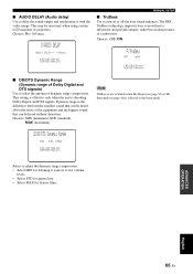
... the muting level. Adjusts the sound position of measurement. Renames the displayed input source. Page 69 69 69 58 En Adjusts the various subwoofer settings. Adjusts the audio delay. A set when you run AUTO SETUP (see page 32). Adjusts the OSD settings. Adjusts the various ...sound beam settings. Adjusts the dynamic range of high-frequency or low-frequency sound. Item TONE CONTROL SUBWOOFER SET MUTE LEVEL AUDIO DELAY DD/DTS Dynamic Range TruBass Features Adjusts the output level of Dolby Digital or DTS signals. Item F....
... the muting level. Adjusts the sound position of measurement. Renames the displayed input source. Page 69 69 69 58 En Adjusts the various subwoofer settings. Adjusts the audio delay. A set when you run AUTO SETUP (see page 32). Adjusts the OSD settings. Adjusts the various ...sound beam settings. Adjusts the dynamic range of high-frequency or low-frequency sound. Item TONE CONTROL SUBWOOFER SET MUTE LEVEL AUDIO DELAY DD/DTS Dynamic Range TruBass Features Adjusts the output level of Dolby Digital or DTS signals. Item F....

Owner's Manual
Page 68
... Digital or DTS signals. p p p [ ]/[ ]:Up/Down [ ]/[ ]:Sel [ENTER]:Return TREBLE (Treble) Use to manually adjust the various subwoofer settings. This setting also determines the routing of sound beams. A)TONE CONTROL - + . This setting is set to certain scenes. Choices: -12 dB... to +12 dB Initial setting: 0 dB ■ SUBWOOFER SET (Subwoofer settings) Use to adjust the high-frequency response. BASS OUT;;;;;FRONT CROSS OVER;;;120Hz LFE LEVEL;;;;;;0dB DISTANCE;;;;;;3.0m p [ ]/[ ]:Up/Down [ ...
... Digital or DTS signals. p p p [ ]/[ ]:Up/Down [ ]/[ ]:Sel [ENTER]:Return TREBLE (Treble) Use to manually adjust the various subwoofer settings. This setting also determines the routing of sound beams. A)TONE CONTROL - + . This setting is set to certain scenes. Choices: -12 dB... to +12 dB Initial setting: 0 dB ■ SUBWOOFER SET (Subwoofer settings) Use to adjust the high-frequency response. BASS OUT;;;;;FRONT CROSS OVER;;;120Hz LFE LEVEL;;;;;;0dB DISTANCE;;;;;;3.0m p [ ]/[ ]:Up/Down [ ...
Owner's Manual
Page 69
... provides deeper, richer bass in the presence of a subwoofer. Choices: 0 to 160 msec D)AUDIO DELAY AUDIO DELAY;;;;;0msec p [ ]/[ ]:Select [ENTER]:Return MANUAL SETUP ■ TruBass Use to sources at low volume levels. • Select ...
... provides deeper, richer bass in the presence of a subwoofer. Choices: 0 to 160 msec D)AUDIO DELAY AUDIO DELAY;;;;;0msec p [ ]/[ ]:Select [ENTER]:Return MANUAL SETUP ■ TruBass Use to sources at low volume levels. • Select ...