
Owner's Manual
Page 1
UA YSP-3000 Digital Sound ProjectorTM OWNER'S MANUAL
UA YSP-3000 Digital Sound ProjectorTM OWNER'S MANUAL
Owner's Manual
Page 3
... Ave, Buena Park, CA 90620. IMPORTANT SAFETY INSTRUCTIONS FCC INFORMATION (for Class "B" digital devices. IMPORTANT NOTICE: DO NOT MODIFY THIS UNIT! Modifications not expressly approved by Yamaha may cause interference harmful to comply with FCC regulations does not guarantee that interference will ...and clear without affecting your FCC authorization to avoid prolonged exposure from loud sounds is often undetectable until it at a safe level. We Want You Listening For A Lifetime Yamaha and the Electronic Industries Association's Consumer Electronics Group want you to get ...
... Ave, Buena Park, CA 90620. IMPORTANT SAFETY INSTRUCTIONS FCC INFORMATION (for Class "B" digital devices. IMPORTANT NOTICE: DO NOT MODIFY THIS UNIT! Modifications not expressly approved by Yamaha may cause interference harmful to comply with FCC regulations does not guarantee that interference will ...and clear without affecting your FCC authorization to avoid prolonged exposure from loud sounds is often undetectable until it at a safe level. We Want You Listening For A Lifetime Yamaha and the Electronic Industries Association's Consumer Electronics Group want you to get ...
Owner's Manual
Page 4
.... IMPORTANT Please record the serial number of plug to obstruct heat radiation. This Class B digital apparatus complies with the letter L or coloured RED. Other components, as it in a ...If the socket outlets in the home are complete. 8 Do not operate this unit may result in a safe place for future reference. 2 Install this sound system in order not to wide ... unit to the instructions described below ) this Owner's Manual in hazardous radiation exposure. Yamaha will form when the surrounding temperature changes suddenly. FOR CANADIAN CUSTOMERS To prevent electric shock...
.... IMPORTANT Please record the serial number of plug to obstruct heat radiation. This Class B digital apparatus complies with the letter L or coloured RED. Other components, as it in a ...If the socket outlets in the home are complete. 8 Do not operate this unit may result in a safe place for future reference. 2 Install this sound system in order not to wide ... unit to the instructions described below ) this Owner's Manual in hazardous radiation exposure. Yamaha will form when the surrounding temperature changes suddenly. FOR CANADIAN CUSTOMERS To prevent electric shock...
Owner's Manual
Page 5
...tuning 49 Automatic preset tuning 50 Manual preset tuning 51 Selecting a preset station 52 Displaying the Radio Data System information (Europe model only 52 Enjoying surround sound 54 5 Beam 54 Stereo plus 3 Beam 55 3 Beam 55 My Surround 55 Enjoying 2-channel sources in surround... components 20 Connections using HDMI cables 21 Connecting a TV 22 Connecting a DVD player/recorder 23 Connecting a digital satellite tuner or a cable TV tuner 24 Connecting a digital airwave tuner 25 Connecting a portable audio player 26 Connecting other components 97 Using the TV macro 100 BASIC ...
...tuning 49 Automatic preset tuning 50 Manual preset tuning 51 Selecting a preset station 52 Displaying the Radio Data System information (Europe model only 52 Enjoying surround sound 54 5 Beam 54 Stereo plus 3 Beam 55 3 Beam 55 My Surround 55 Enjoying 2-channel sources in surround... components 20 Connections using HDMI cables 21 Connecting a TV 22 Connecting a DVD player/recorder 23 Connecting a digital satellite tuner or a cable TV tuner 24 Connecting a digital airwave tuner 25 Connecting a portable audio player 26 Connecting other components 97 Using the TV macro 100 BASIC ...
Owner's Manual
Page 6
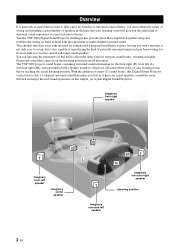
...theater. The YSP-3000 projects sound beams containing surround sound information for the front right (R), front left (L), surround right (SR), and surround left speaker 2 En With the addition of center (C) sound beams, this unit to fully enjoy the benefits of surround sound at home,...21 full-range small speakers. Yamaha YSP-3000 Digital Sound Projector challenges this simple, yet stylish Digital Sound Projector. You can fine-tune the parameters of this Digital Sound Projector creates true-to set up, but is not only easy to -life 5.1-channel surround sound that makes you have been ...
...theater. The YSP-3000 projects sound beams containing surround sound information for the front right (R), front left (L), surround right (SR), and surround left speaker 2 En With the addition of center (C) sound beams, this unit to fully enjoy the benefits of surround sound at home,...21 full-range small speakers. Yamaha YSP-3000 Digital Sound Projector challenges this simple, yet stylish Digital Sound Projector. You can fine-tune the parameters of this Digital Sound Projector creates true-to set up, but is not only easy to -life 5.1-channel surround sound that makes you have been ...
Owner's Manual
Page 7
... version of Dolby Pro Logic that let you experience movies at home with preset remote control codes used to control the DVD player, VCR, cable TV tuner, and digital satellite tuner connected to this unit is the standard audio signal format...Features Digital Sound Projector™ The Digital Sound Projector technology allows one slim unit to control and steer multiple channels of sound to generate multi-channel surround sound, thus eliminates the need for satellite loudspeakers and cabling normally associated with DiMAGIC's Euphony technology and Yamaha's Beam reproduction system. ...
... version of Dolby Pro Logic that let you experience movies at home with preset remote control codes used to control the DVD player, VCR, cable TV tuner, and digital satellite tuner connected to this unit is the standard audio signal format...Features Digital Sound Projector™ The Digital Sound Projector technology allows one slim unit to control and steer multiple channels of sound to generate multi-channel surround sound, thus eliminates the need for satellite loudspeakers and cabling normally associated with DiMAGIC's Euphony technology and Yamaha's Beam reproduction system. ...
Owner's Manual
Page 8
... Labs, Inc. TruBass, SRS and the " " symbol are registered trademarks of YAMAHA Corporation. TruBass technology is a trademark of DiMAGIC Co., Ltd. The " " logo and "Cinema DSP" are registered trademarks of SRS Labs, Inc. Worldwide patents applied for. The " " logo and "Digital Sound Projector™" are trademarks of Dolby Laboratories. "Dolby", "Pro Logic", and the...
... Labs, Inc. TruBass, SRS and the " " symbol are registered trademarks of YAMAHA Corporation. TruBass technology is a trademark of DiMAGIC Co., Ltd. The " " logo and "Cinema DSP" are registered trademarks of SRS Labs, Inc. Worldwide patents applied for. The " " logo and "Digital Sound Projector™" are trademarks of Dolby Laboratories. "Dolby", "Pro Logic", and the...
Owner's Manual
Page 9
See "Installation" on the supplied remote control of this unit. See "Enjoying surround sound" on page 96. 5 En English See "MANUAL SETUP" on page 72 and "Remote control features" on page 54. In case of improvements, etc. See "Getting ...
See "Installation" on the supplied remote control of this unit. See "Enjoying surround sound" on page 96. 5 En English See "MANUAL SETUP" on page 72 and "Remote control features" on page 54. In case of improvements, etc. See "Getting ...

Owner's Manual
Page 10
...(iPod/XM Radio) (×1) UA YSP-3000 Digital Sound ProjectorTM Reference Guide for Yamaha YSP-3000 Digital Sound Projector. Operations in this guide use the ...digital audio output of cloth on . y The illustrations used for U.S.A. and Canada models only 5 Connecting XM Mini-Tuner Home Dock 5 Activating XM Satellite Radio ...6 Basic XM Satellite Radio operations ...6 Presetting the XM Satellite Radio channels 9 Displaying the XM Satellite Radio information 10 Troubleshooting ...11 (U.S.A., Canada, and Australia models only) QUICK REFERENCE GUIDE YSP-3000...
...(iPod/XM Radio) (×1) UA YSP-3000 Digital Sound ProjectorTM Reference Guide for Yamaha YSP-3000 Digital Sound Projector. Operations in this guide use the ...digital audio output of cloth on . y The illustrations used for U.S.A. and Canada models only 5 Connecting XM Mini-Tuner Home Dock 5 Activating XM Satellite Radio ...6 Basic XM Satellite Radio operations ...6 Presetting the XM Satellite Radio channels 9 Displaying the XM Satellite Radio information 10 Troubleshooting ...11 (U.S.A., Canada, and Australia models only) QUICK REFERENCE GUIDE YSP-3000...
Owner's Manual
Page 11
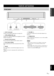
... (see page 26). 2 INTELLIBEAM MIC jack Connect the supplied IntelliBeam microphone for HDMI signals. Notes • When you will hear a click sound followed by the 4 to 5-second interval before sound reproducing. • In the standby mode, this unit consumes a small amount of power in order to receive infrared signals from the remote... Outputs a test tone to search for AUTO SETUP (see page 36). 3 Remote control sensor Receives infrared signals from the remote control or to experience the sound beam (see page 31).
... (see page 26). 2 INTELLIBEAM MIC jack Connect the supplied IntelliBeam microphone for HDMI signals. Notes • When you will hear a click sound followed by the 4 to 5-second interval before sound reproducing. • In the standby mode, this unit consumes a small amount of power in order to receive infrared signals from the remote... Outputs a test tone to search for AUTO SETUP (see page 36). 3 Remote control sensor Receives infrared signals from the remote control or to experience the sound beam (see page 31).
Owner's Manual
Page 12
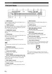
... the DOCK terminal on (see page 79). 0 EQUAL indicator Lights up when a sound field program is selected (see page 56). C Radio Data System indicators (Europe model only) Show the current Radio Data System status. y You can adjust the brightness and display setting of the night listening enhancers... Lights up when the TV volume equal mode is selected (see page 67). Note The neural decoder is reproducing PCM (Pulse Code Modulation) digital audio signals. 5 Decoder indicators Light up when the corresponding decoder operates (see page 64). 4 PCM indicator Lights up when this unit. ...
... the DOCK terminal on (see page 79). 0 EQUAL indicator Lights up when a sound field program is selected (see page 56). C Radio Data System indicators (Europe model only) Show the current Radio Data System status. y You can adjust the brightness and display setting of the night listening enhancers... Lights up when the TV volume equal mode is selected (see page 67). Note The neural decoder is reproducing PCM (Pulse Code Modulation) digital audio signals. 5 Decoder indicators Light up when the corresponding decoder operates (see page 64). 4 PCM indicator Lights up when this unit. ...
Owner's Manual
Page 14
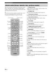
...components" on the TV (see page 97). DECODE 0 +10 ENHANCER ENTRY MENU A-E DISPLAY ENTER TV/AV YSP RETURN VOLUME CH TV VOL MUTE TV INPUT TV MUTE CH LEVEL TEST CODE SET H I ** J* K...3 STEREO 4 MY BEAM 5 MY SUR. 6 MUSIC 7 MOVIE 8 SPORTS 9 OFF SUR. B MUTE Mutes the sound. A VOLUME +/- D CH LEVEL Adjusts the volume level of each channel (see page 66). 9 Cursor buttons /...Displays information on the selected input signal. Increases or decreases the volume level of this system to the standby mode (see page 31). 3 Transmission indicator Lights up when infrared control...
...components" on the TV (see page 97). DECODE 0 +10 ENHANCER ENTRY MENU A-E DISPLAY ENTER TV/AV YSP RETURN VOLUME CH TV VOL MUTE TV INPUT TV MUTE CH LEVEL TEST CODE SET H I ** J* K...3 STEREO 4 MY BEAM 5 MY SUR. 6 MUSIC 7 MOVIE 8 SPORTS 9 OFF SUR. B MUTE Mutes the sound. A VOLUME +/- D CH LEVEL Adjusts the volume level of each channel (see page 66). 9 Cursor buttons /...Displays information on the selected input signal. Increases or decreases the volume level of this system to the standby mode (see page 31). 3 Transmission indicator Lights up when infrared control...
Owner's Manual
Page 17
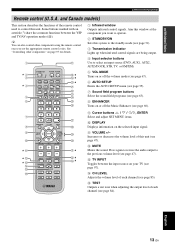
...this window at the component you set the appropriate remote control codes. B MUTE Mutes the sound. Press again to restore the audio output to select an input source (DVD, AUX1,... Displays information on your TV (see page 47). English 13 En DECODE 0 +10 ENHANCER ENTRY MENU CAT/ A-E DISPLAY ENTER TV/AV YSP RETURN VOLUME CH TV VOL MUTE TV INPUT TV MUTE CODE SET CH LEVEL TEST G H I ** J* K L M N O...components using the remote control once you want to operate. 2 STANDBY/ON Sets this system to the standby mode (see page 31). 3 Transmission indicator Lights up when infrared...
...this window at the component you set the appropriate remote control codes. B MUTE Mutes the sound. Press again to restore the audio output to select an input source (DVD, AUX1,... Displays information on your TV (see page 47). English 13 En DECODE 0 +10 ENHANCER ENTRY MENU CAT/ A-E DISPLAY ENTER TV/AV YSP RETURN VOLUME CH TV VOL MUTE TV INPUT TV MUTE CODE SET CH LEVEL TEST G H I ** J* K L M N O...components using the remote control once you want to operate. 2 STANDBY/ON Sets this system to the standby mode (see page 31). 3 Transmission indicator Lights up when infrared...
Owner's Manual
Page 20
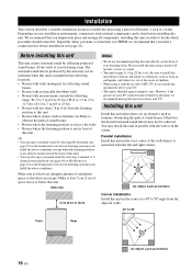
...this unit). • You can escape. Especially when you make a connection first before installing this unit. The surround sound effects produced by selecting My Surround (see page 55) as the beam mode even if your listening room may install this... not install this unit directly above conditions (except when the listening position is installed in the following locations. • Rooms with walls inadequate for reflecting sound beams • Rooms with acoustically absorbent walls • Rooms with measurements outside the following range: W (3 to 7 m (10 to 23 ft)) x H (2 to...
...this unit). • You can escape. Especially when you make a connection first before installing this unit. The surround sound effects produced by selecting My Surround (see page 55) as the beam mode even if your listening room may install this... not install this unit directly above conditions (except when the listening position is installed in the following locations. • Rooms with walls inadequate for reflecting sound beams • Rooms with acoustically absorbent walls • Rooms with measurements outside the following range: W (3 to 7 m (10 to 23 ft)) x H (2 to...
Owner's Manual
Page 21
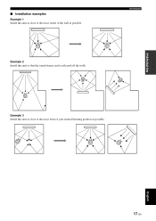
Example 2 Install this unit as close to the exact front of the wall as possible. PREPARATION ■ Installation examples Example 1 Install this unit as close to the exact center of your normal listening position as possible. English 17 En Installation Example 3 Install this unit so that the sound beams can be reflected off the walls.
Example 2 Install this unit as close to the exact front of the wall as possible. PREPARATION ■ Installation examples Example 1 Install this unit as close to the exact center of your normal listening position as possible. English 17 En Installation Example 3 Install this unit so that the sound beams can be reflected off the walls.
Owner's Manual
Page 23
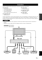
... complete. • Unplug the AC power supply cable before changing connections, moving or cleaning this unit, you can enjoy reinforced low-bass sounds. CAUTION • Do not connect this unit or other components to this unit. For details on how to connect various types of analog...Connections This unit is equipped with the following types of audio/video input/output jacks/terminal: For audio input • 2 optical digital input jacks • 2 coaxial digital input jacks • 2 sets of external components to this unit, see pages 21 to connect external components such as your TV...
... complete. • Unplug the AC power supply cable before changing connections, moving or cleaning this unit, you can enjoy reinforced low-bass sounds. CAUTION • Do not connect this unit or other components to this unit. For details on how to connect various types of analog...Connections This unit is equipped with the following types of audio/video input/output jacks/terminal: For audio input • 2 optical digital input jacks • 2 coaxial digital input jacks • 2 sets of external components to this unit, see pages 21 to connect external components such as your TV...
Owner's Manual
Page 32
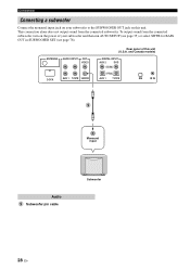
...or select SWFR for BASS OUT in SUBWOOFER SET (see page 78). This connection alone does not output sound from the connected subwoofer, turn on this unit (U.S.A. To output sound from the connected subwoofer. ANTENNA AUDIO INPUT OUT VIDEO DOCK AUX 1 TV/STB SUBWOOFER Rear panel of your... subwoofer to the SUBWOOFER OUT jack on the power of this unit. and Canada models) DIGITAL INPUT AUX 2 DVD COAXIAL OPTICAL AUX 1...
...or select SWFR for BASS OUT in SUBWOOFER SET (see page 78). This connection alone does not output sound from the connected subwoofer, turn on this unit (U.S.A. To output sound from the connected subwoofer. ANTENNA AUDIO INPUT OUT VIDEO DOCK AUX 1 TV/STB SUBWOOFER Rear panel of your... subwoofer to the SUBWOOFER OUT jack on the power of this unit. and Canada models) DIGITAL INPUT AUX 2 DVD COAXIAL OPTICAL AUX 1...
Owner's Manual
Page 36
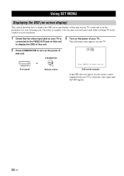
The following screen appears on your TV to switch the video input until the OSD appears. 32 En YSP-3000 or STANDBY/ON Front panel Remote control Push [MENU] to begin set the parameters for your TV. STANDBY/ON 3 Turn on the power of your ... how to display the OSD (on-screen display) of this unit. Once this is complete, you can enjoy real surround sound while watching TV in the comfort of your own home. 1 Check that the video input jack on your TV is connected to the VIDEO OUT jack on this unit to display...
The following screen appears on your TV to switch the video input until the OSD appears. 32 En YSP-3000 or STANDBY/ON Front panel Remote control Push [MENU] to begin set the parameters for your TV. STANDBY/ON 3 Turn on the power of your ... how to display the OSD (on-screen display) of this unit. Once this is complete, you can enjoy real surround sound while watching TV in the comfort of your own home. 1 Check that the video input jack on your TV is connected to the VIDEO OUT jack on this unit to display...
Owner's Manual
Page 37
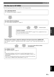
... following diagram illustrates the overall flow of error messages and possible remedies. Using SET MENU Run AUTO SETUP (IntelliBeam). If you cannot clearly hear a sound beam from a specific channel, adjust settings for SETTING PARAMETERS (see page 74) or for BEAM ADJUSTMENT (see page 75) in BEAM MENU. •... SETUP" on page 34. Run LANGUAGE SETUP. See "Error messages for AUTO SETUP" on page 41 for TREBLE GAIN in the path of the sound beams, adjust settings for a complete list of the setup procedure. See "AUTO SETUP (IntelliBeam)" on page 63. Play back audio signals or adjust...
... following diagram illustrates the overall flow of error messages and possible remedies. Using SET MENU Run AUTO SETUP (IntelliBeam). If you cannot clearly hear a sound beam from a specific channel, adjust settings for SETTING PARAMETERS (see page 74) or for BEAM ADJUSTMENT (see page 75) in BEAM MENU. •... SETUP" on page 34. Run LANGUAGE SETUP. See "Error messages for AUTO SETUP" on page 41 for TREBLE GAIN in the path of the sound beams, adjust settings for a complete list of the setup procedure. See "AUTO SETUP (IntelliBeam)" on page 63. Play back audio signals or adjust...
Owner's Manual
Page 39
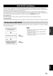
... procedure is skipped if BEAM OPTIMZ only is selected. *2 *3 Checking the subwoofer and optimizing the beam delay, frequency, and volume Sound optimization SETUP English 35 En The flow chart of AUTO SETUP This unit performs a series of the supplied IntelliBeam microphone, allowing you to...aid of checks to enjoy the best possible sound from this unit. Sound optimization: This feature optimizes the beam delay, volume, and quality so that the parameter best matches your listening environment. Checking the environment of other audio systems, you would arrange the speaker position of...
... procedure is skipped if BEAM OPTIMZ only is selected. *2 *3 Checking the subwoofer and optimizing the beam delay, frequency, and volume Sound optimization SETUP English 35 En The flow chart of AUTO SETUP This unit performs a series of the supplied IntelliBeam microphone, allowing you to...aid of checks to enjoy the best possible sound from this unit. Sound optimization: This feature optimizes the beam delay, volume, and quality so that the parameter best matches your listening environment. Checking the environment of other audio systems, you would arrange the speaker position of...


