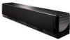
Owner's Manual
Page 5
...Connecting a TV 22 Connecting a DVD player/recorder 23 Connecting a digital satellite tuner or a cable TV tuner 24 Connecting a digital airwave tuner 25 Connecting a portable audio player 26 Connecting other ... tuning 51 Selecting a preset station 52 Displaying the Radio Data System information (Europe model only 52 Enjoying surround sound 54 5 Beam 54 Stereo plus 3 Beam 55 3 Beam 55 ...Supplied accessories 6 Controls and functions 7 Front panel 7 Front panel display 8 Rear panel 9 Remote control (Europe, Australia, Asia, and Korea models) ..... 10 Remote control (U.S.A.
...Connecting a TV 22 Connecting a DVD player/recorder 23 Connecting a digital satellite tuner or a cable TV tuner 24 Connecting a digital airwave tuner 25 Connecting a portable audio player 26 Connecting other ... tuning 51 Selecting a preset station 52 Displaying the Radio Data System information (Europe model only 52 Enjoying surround sound 54 5 Beam 54 Stereo plus 3 Beam 55 3 Beam 55 ...Supplied accessories 6 Controls and functions 7 Front panel 7 Front panel display 8 Rear panel 9 Remote control (Europe, Australia, Asia, and Korea models) ..... 10 Remote control (U.S.A.
Owner's Manual
Page 10
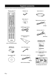
...The illustrations used for Yamaha YSP-3000 Digital Sound Projector. The XM name and...DIGITAL INPUT AUX 2 DVD COAXIAL YSP-3000 AUX 1 TV/STB SUBWOOFER AUX 1 TV/STB Subwoofer Audio connection * The rear panel...Home Dock 5 Activating XM Satellite Radio ...6 Basic XM Satellite Radio operations ...6 Presetting the XM Satellite Radio channels 9 Displaying the XM Satellite Radio information 10 Troubleshooting ...11 (U.S.A., Canada, and Australia models only) QUICK REFERENCE GUIDE YSP-3000 QUICK REFERENCE GUIDE Items used in this unit. Install this unit and achieve the surround sound...
...The illustrations used for Yamaha YSP-3000 Digital Sound Projector. The XM name and...DIGITAL INPUT AUX 2 DVD COAXIAL YSP-3000 AUX 1 TV/STB SUBWOOFER AUX 1 TV/STB Subwoofer Audio connection * The rear panel...Home Dock 5 Activating XM Satellite Radio ...6 Basic XM Satellite Radio operations ...6 Presetting the XM Satellite Radio channels 9 Displaying the XM Satellite Radio information 10 Troubleshooting ...11 (U.S.A., Canada, and Australia models only) QUICK REFERENCE GUIDE YSP-3000 QUICK REFERENCE GUIDE Items used in this unit. Install this unit and achieve the surround sound...
Owner's Manual
Page 11
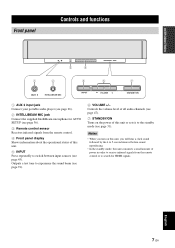
... for AUTO SETUP (see page 36). 3 Remote control sensor Receives infrared signals from the remote control. 4 Front panel display Shows information about the operational status of this unit. 5 INPUT Press repeatedly to experience the sound beam (see page 45). Outputs a test tone to switch between input sources (see page 91). 6 VOLUME +/- Notes...
... for AUTO SETUP (see page 36). 3 Remote control sensor Receives infrared signals from the remote control. 4 Front panel display Shows information about the operational status of this unit. 5 INPUT Press repeatedly to experience the sound beam (see page 45). Outputs a test tone to switch between input sources (see page 91). 6 VOLUME +/- Notes...
Owner's Manual
Page 12
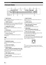
...models only). 3 CINEMA DSP indicator Lights up when a sound field program is selected (see page 64). 4 PCM indicator...) Show the current Radio Data System status. E Multi-information display Shows information with alphanumeric characters when you adjust the parameters of this unit is reproducing PCM (Pulse Code Modulation) digital audio signals. 5 Decoder indicators ...Lights up when TruBass is turned on (see page 79). 0 EQUAL indicator Lights up when this unit. Controls and functions Front panel display 1 2 3 4 5 67 890A B C D E F 1 HDMI indicator Lights up when the signal of the ...
...models only). 3 CINEMA DSP indicator Lights up when a sound field program is selected (see page 64). 4 PCM indicator...) Show the current Radio Data System status. E Multi-information display Shows information with alphanumeric characters when you adjust the parameters of this unit is reproducing PCM (Pulse Code Modulation) digital audio signals. 5 Decoder indicators ...Lights up when TruBass is turned on (see page 79). 0 EQUAL indicator Lights up when this unit. Controls and functions Front panel display 1 2 3 4 5 67 890A B C D E F 1 HDMI indicator Lights up when the signal of the ...
Owner's Manual
Page 13
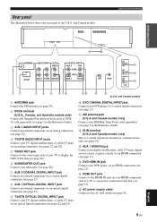
... panel of this unit (see page 2 in the Reference Guide). F AC power supply cable Connect to display the OSD of the U.S.A. A XM antenna jack (U.S.A and Canada models only) Connect your TV to the AC wall outlet (see page 29). and Canada models) 0 DVD COAXIAL DIGITAL ... E OUT HDMI 12 3 4 5 6 78 1 ANTENNA jack Connect the FM antenna (see page 29). 2 DOCK terminal (U.S.A., Canada, and Australia models only) Connect the Yamaha iPod universal dock (such as a TV or a projector connected to the video input jack of your XM Mini-Tuner Dock (sold separately) (see page 21).
... panel of this unit (see page 2 in the Reference Guide). F AC power supply cable Connect to display the OSD of the U.S.A. A XM antenna jack (U.S.A and Canada models only) Connect your TV to the AC wall outlet (see page 29). and Canada models) 0 DVD COAXIAL DIGITAL ... E OUT HDMI 12 3 4 5 6 78 1 ANTENNA jack Connect the FM antenna (see page 29). 2 DOCK terminal (U.S.A., Canada, and Australia models only) Connect the Yamaha iPod universal dock (such as a TV or a projector connected to the video input jack of your XM Mini-Tuner Dock (sold separately) (see page 21).
Owner's Manual
Page 24
... Digital, DTS, PCM Notes • When CPPM copy-protected DVD audio is played back, video and audio signals may not be sure to put the cap back in the cable clamp. When you use an HDMI cable shorter than 5 m (16 ft) with the HDMI logo printed on it to the rear panel... of DVD player. • This unit is correct. Cap ■ Affixing cables To prevent cables from a single source component, this unit plays back the audio signals in the following priority order: HDMI → Digital → Analog As default settings, the following input...
... Digital, DTS, PCM Notes • When CPPM copy-protected DVD audio is played back, video and audio signals may not be sure to put the cap back in the cable clamp. When you use an HDMI cable shorter than 5 m (16 ft) with the HDMI logo printed on it to the rear panel... of DVD player. • This unit is correct. Cap ■ Affixing cables To prevent cables from a single source component, this unit plays back the audio signals in the following priority order: HDMI → Digital → Analog As default settings, the following input...
Owner's Manual
Page 25
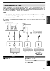
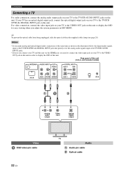
... on your TV and this unit via the HDMI jack, you secure the HDMI cable(s) with 2 HDMI input jacks and 1 HDMI output jack. Rear panel of this unit. PREPARATION Connections Connections using HDMI cables This unit is in the standby mode, the signals input at the HDMI IN jacks are... HDMI cables for simpler and easier connections, and you have connected the HDMI cable(s) to OFF (see page 82) and this unit OUT VIDEO SUBWOOFER DIGITAL INPUT AUX 2 DVD COAXIAL OPTICAL AUX 1 TV/STB AUX 1 DVD IN OUT HDMI * This connection (except for a game console) is not necessary if your ...
... on your TV and this unit via the HDMI jack, you secure the HDMI cable(s) with 2 HDMI input jacks and 1 HDMI output jack. Rear panel of this unit. PREPARATION Connections Connections using HDMI cables This unit is in the standby mode, the signals input at the HDMI IN jacks are... HDMI cables for simpler and easier connections, and you have connected the HDMI cable(s) to OFF (see page 82) and this unit OUT VIDEO SUBWOOFER DIGITAL INPUT AUX 2 DVD COAXIAL OPTICAL AUX 1 TV/STB AUX 1 DVD IN OUT HDMI * This connection (except for a game console) is not necessary if your ...
Owner's Manual
Page 26
...affix the optical cable in SET MENU. If your TV has an optical digital output jack, connect the optical digital output jack on your TV and this unit. Rear panel of this unit via the HDMI jack, you adjust the system parameters in the supplied cable clamp (see page 20). and Canada models)... ANTENNA AUDIO INPUT OUT VIDEO DOCK AUX 1 TV/STB SUBWOOFER DIGITAL INPUT AUX 2 DVD COAXIAL OPTICAL AUX 1 TV/...
...affix the optical cable in SET MENU. If your TV has an optical digital output jack, connect the optical digital output jack on your TV and this unit. Rear panel of this unit via the HDMI jack, you adjust the system parameters in the supplied cable clamp (see page 20). and Canada models)... ANTENNA AUDIO INPUT OUT VIDEO DOCK AUX 1 TV/STB SUBWOOFER DIGITAL INPUT AUX 2 DVD COAXIAL OPTICAL AUX 1 TV/...
Owner's Manual
Page 27
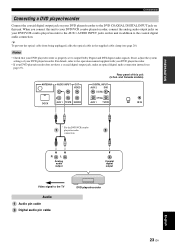
...1 TV/STB SUBWOOFER DIGITAL INPUT AUX 2 DVD COAXIAL OPTICAL AUX ...digital output Video signal to output Dolby Digital and DTS digital audio signals. Rear panel of your DVD player/recorder is properly set to the TV Audio Audio pin cable Digital... audio pin cable DVD player/recorder English 23 En PREPARATION Connections Connecting a DVD player/recorder Connect the coaxial digital... a coaxial digital output jack, make an optical digital audio connection ...
...1 TV/STB SUBWOOFER DIGITAL INPUT AUX 2 DVD COAXIAL OPTICAL AUX ...digital output Video signal to output Dolby Digital and DTS digital audio signals. Rear panel of your DVD player/recorder is properly set to the TV Audio Audio pin cable Digital... audio pin cable DVD player/recorder English 23 En PREPARATION Connections Connecting a DVD player/recorder Connect the coaxial digital... a coaxial digital output jack, make an optical digital audio connection ...
Owner's Manual
Page 28
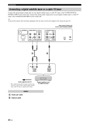
...AUDIO INPUT OUT VIDEO DOCK AUX 1 TV/STB SUBWOOFER Rear panel of this unit. Digital satellite tuner or cable TV tuner Audio Audio pin cable Optical cable 24 En Connections Connecting a digital satellite tuner or a cable TV tuner Connect the optical digital output jack on your TV has a built-in the ... to the TV * This connection (except for a game console) is not necessary if your digital satellite tuner or cable TV tuner to the TV/STB OPTICAL DIGITAL INPUT jack on this unit. and Canada models) DIGITAL INPUT AUX 2 DVD COAXIAL OPTICAL AUX 1 TV/STB XM IR IN R L Analog audio...
...AUDIO INPUT OUT VIDEO DOCK AUX 1 TV/STB SUBWOOFER Rear panel of this unit. Digital satellite tuner or cable TV tuner Audio Audio pin cable Optical cable 24 En Connections Connecting a digital satellite tuner or a cable TV tuner Connect the optical digital output jack on your TV has a built-in the ... to the TV * This connection (except for a game console) is not necessary if your digital satellite tuner or cable TV tuner to the TV/STB OPTICAL DIGITAL INPUT jack on this unit. and Canada models) DIGITAL INPUT AUX 2 DVD COAXIAL OPTICAL AUX 1 TV/STB XM IR IN R L Analog audio...
Owner's Manual
Page 29
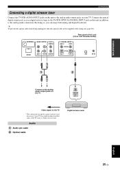
... so, you can enjoy both analog and digital broadcasts. y To prevent the optical cable from being unplugged, affix the optical cable in the supplied cable clamp (see page 20). ANTENNA AUDIO INPUT OUT VIDEO DOCK AUX 1 TV/STB SUBWOOFER Rear panel of this unit in addition to the analog... audio connection. Connect the optical digital output jack on your digital airwave tuner to the analog audio output jacks on the TV. Connections Connecting...
... so, you can enjoy both analog and digital broadcasts. y To prevent the optical cable from being unplugged, affix the optical cable in the supplied cable clamp (see page 20). ANTENNA AUDIO INPUT OUT VIDEO DOCK AUX 1 TV/STB SUBWOOFER Rear panel of this unit in addition to the analog... audio connection. Connect the optical digital output jack on your digital airwave tuner to the analog audio output jacks on the TV. Connections Connecting...
Owner's Manual
Page 30
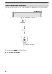
Connections Connecting a portable audio player Connect the analog audio output jack on your portable audio player to the AUX 3 input jack on the front panel of this unit. Front panel of this unit AUX 3 Analog audio output Portable audio player Audio 3.5 mm stereo mini plug cable 26 En
Connections Connecting a portable audio player Connect the analog audio output jack on your portable audio player to the AUX 3 input jack on the front panel of this unit. Front panel of this unit AUX 3 Analog audio output Portable audio player Audio 3.5 mm stereo mini plug cable 26 En
Owner's Manual
Page 31
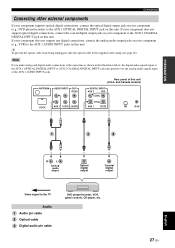
...y To prevent the optical cable from being unplugged, affix the optical cable in the illustration below, the digital audio signals input at the AUX 1 OPTICAL DIGITAL INPUT or AUX 2 COAXIAL DIGITAL INPUT jack take priority over the analog audio signals input at the AUX 1 AUDIO INPUT jacks. ANTENNA ...AUDIO INPUT OUT VIDEO DOCK AUX 1 TV/STB SUBWOOFER Rear panel of this unit. If your component does not support optical digital connections, connect the coaxial digital output jack on your component (e.g., VCR) to the AUX 2 COAXIAL...
...y To prevent the optical cable from being unplugged, affix the optical cable in the illustration below, the digital audio signals input at the AUX 1 OPTICAL DIGITAL INPUT or AUX 2 COAXIAL DIGITAL INPUT jack take priority over the analog audio signals input at the AUX 1 AUDIO INPUT jacks. ANTENNA ...AUDIO INPUT OUT VIDEO DOCK AUX 1 TV/STB SUBWOOFER Rear panel of this unit. If your component does not support optical digital connections, connect the coaxial digital output jack on your component (e.g., VCR) to the AUX 2 COAXIAL...
Owner's Manual
Page 32
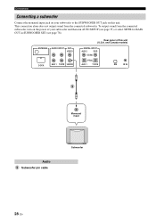
and Canada models) DIGITAL INPUT AUX 2 DVD COAXIAL OPTICAL AUX 1 TV/STB XM IR IN 5 Monaural input Audio 5 Subwoofer pin cable Subwoofer 28 En ANTENNA AUDIO INPUT OUT VIDEO DOCK AUX 1 TV/STB SUBWOOFER Rear panel of your subwoofer to the SUBWOOFER OUT jack on your subwoofer and then ...run AUTO SETUP (see page 35) or select SWFR for BASS OUT in SUBWOOFER SET (see page 78). To output sound from the connected subwoofer. Connections Connecting a subwoofer...
and Canada models) DIGITAL INPUT AUX 2 DVD COAXIAL OPTICAL AUX 1 TV/STB XM IR IN 5 Monaural input Audio 5 Subwoofer pin cable Subwoofer 28 En ANTENNA AUDIO INPUT OUT VIDEO DOCK AUX 1 TV/STB SUBWOOFER Rear panel of your subwoofer to the SUBWOOFER OUT jack on your subwoofer and then ...run AUTO SETUP (see page 35) or select SWFR for BASS OUT in SUBWOOFER SET (see page 78). To output sound from the connected subwoofer. Connections Connecting a subwoofer...
Owner's Manual
Page 33
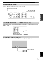
DIGITAL INPUT AUX 2 DVD COAXIAL OPTICAL AUX 1 TV/STB Rear panel of this unit (U.S.A. This is a control expansion terminal for ... and Canada models only) The IR IN terminal does not support normal external component connection. and Canada models) DIGITAL INPUT AUX 2 DVD COAXIAL OPTICAL AUX 1 TV/STB XM IR IN About the IR IN terminal (U.S.A. FM ...indoor antenna (supplied) Connections ANTENNA AUDIO INPUT OUT VIDEO DOCK AUX 1 TV/STB SUBWOOFER Rear panel of this unit. and Canada models) XM IR IN IR IN terminal Connecting the AC power supply cable ...
DIGITAL INPUT AUX 2 DVD COAXIAL OPTICAL AUX 1 TV/STB Rear panel of this unit (U.S.A. This is a control expansion terminal for ... and Canada models only) The IR IN terminal does not support normal external component connection. and Canada models) DIGITAL INPUT AUX 2 DVD COAXIAL OPTICAL AUX 1 TV/STB XM IR IN About the IR IN terminal (U.S.A. FM ...indoor antenna (supplied) Connections ANTENNA AUDIO INPUT OUT VIDEO DOCK AUX 1 TV/STB SUBWOOFER Rear panel of this unit. and Canada models) XM IR IN IR IN terminal Connecting the AC power supply cable ...
Owner's Manual
Page 35
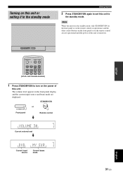
Note When this unit is in the front panel display, and the current input source and beam mode are not operational until the power of... volume level appears in the standby mode, only STANDBY/ON on the front panel or on the remote control is turned on. STANDBY/ON STANDBY/ON Front panel or Remote control VOLUME 30 Current volume level DVD Current input source MY SUR... 31 En English Turning on the power of this unit is operational, and the other control buttons on the front panel or on the remote control are displayed. and Canada models) 1 Press STANDBY/ON to turn on this unit or...
Note When this unit is in the front panel display, and the current input source and beam mode are not operational until the power of... volume level appears in the standby mode, only STANDBY/ON on the front panel or on the remote control is turned on. STANDBY/ON STANDBY/ON Front panel or Remote control VOLUME 30 Current volume level DVD Current input source MY SUR... 31 En English Turning on the power of this unit is operational, and the other control buttons on the front panel or on the remote control are displayed. and Canada models) 1 Press STANDBY/ON to turn on this unit or...
Owner's Manual
Page 36
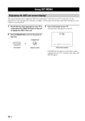
... Using SET MENU Displaying the OSD (on-screen display) This section describes how to display the OSD (on-screen display) of your TV. YSP-3000 or STANDBY/ON Front panel Remote control Push [MENU] to begin set-up OSD screen example If the OSD does not appear, use the remote control supplied with... the power of this unit. The following screen appears on your TV. Once this is complete, you can enjoy real surround sound while watching TV in the comfort of your own home. 1 Check that the video input jack on your TV is connected to the VIDEO OUT jack on this unit to...
... Using SET MENU Displaying the OSD (on-screen display) This section describes how to display the OSD (on-screen display) of your TV. YSP-3000 or STANDBY/ON Front panel Remote control Push [MENU] to begin set-up OSD screen example If the OSD does not appear, use the remote control supplied with... the power of this unit. The following screen appears on your TV. Once this is complete, you can enjoy real surround sound while watching TV in the comfort of your own home. 1 Check that the video input jack on your TV is connected to the VIDEO OUT jack on this unit to...
Owner's Manual
Page 38
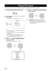
.... ENTER ENTER ;LANGUAGE SETUP . The following operations while viewing information in SET MENU of this unit. 1 Set the operation mode selector to YSP. ENTER ENTER Choices: ENGLISH (English), DEUTSCH (German), Français (French), ESPAÑOL (Spanish), ITALIANO (Italian), NEDERLANDS (Dutch ... p p 34 En The SET MENU screen appears on your choice that appears in the front panel display. 3 Press / to select the desired language, and press ENTER. TV/AV YSP 2 Press MENU. CHANGING OSD LANGUAGE Changing OSD language This feature allows you to select the language...
.... ENTER ENTER ;LANGUAGE SETUP . The following operations while viewing information in SET MENU of this unit. 1 Set the operation mode selector to YSP. ENTER ENTER Choices: ENGLISH (English), DEUTSCH (German), Français (French), ESPAÑOL (Spanish), ITALIANO (Italian), NEDERLANDS (Dutch ... p p 34 En The SET MENU screen appears on your choice that appears in the front panel display. 3 Press / to select the desired language, and press ENTER. TV/AV YSP 2 Press MENU. CHANGING OSD LANGUAGE Changing OSD language This feature allows you to select the language...

Owner's Manual
Page 40
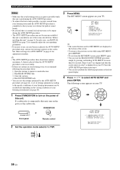
...and the walls in your listening room. AUTO SETUP (IntelliBeam) Installing the IntelliBeam microphone The supplied IntelliBeam microphone collects and analyzes the sound that the IntelliBeam microphone is not properly placed in your listening room. MIN MAX MIN MAX Subwoofer 1 Press STANDBY/ON to heat.... - To avoid the possibility of this unit produces in your listening position. STANDBY/ON or STANDBY/ON Front panel Remote control 2 Connect the supplied IntelliBeam microphone to this unit and make sure that this unit. Follow the procedure below to connect...
...and the walls in your listening room. AUTO SETUP (IntelliBeam) Installing the IntelliBeam microphone The supplied IntelliBeam microphone collects and analyzes the sound that the IntelliBeam microphone is not properly placed in your listening room. MIN MAX MIN MAX Subwoofer 1 Press STANDBY/ON to heat.... - To avoid the possibility of this unit produces in your listening position. STANDBY/ON or STANDBY/ON Front panel Remote control 2 Connect the supplied IntelliBeam microphone to this unit and make sure that this unit. Follow the procedure below to connect...
Owner's Manual
Page 42
...SET MENU screen appears on page 41 for appropriate remedies. Open the curtains to YSP. 3 Press MENU. Close the curtains. 4. STANDBY/ON or STANDBY/ON Front panel Remote control 2 Set the operation mode selector to improve sound reflection. 2. Steps 4 and 5 are skipped and then the screen shown in... TV. y • The AUTO SETUP procedure takes about three minutes maximum. See "Error messages for SET MENU are curtains in the front panel display. 4 Press / to manually adjust the corresponding parameters. • If an error occurs, an error buzzer is played, the AUTO SETUP...
...SET MENU screen appears on page 41 for appropriate remedies. Open the curtains to YSP. 3 Press MENU. Close the curtains. 4. STANDBY/ON or STANDBY/ON Front panel Remote control 2 Set the operation mode selector to improve sound reflection. 2. Steps 4 and 5 are skipped and then the screen shown in... TV. y • The AUTO SETUP procedure takes about three minutes maximum. See "Error messages for SET MENU are curtains in the front panel display. 4 Press / to manually adjust the corresponding parameters. • If an error occurs, an error buzzer is played, the AUTO SETUP...
