Owner's Manual
Page 5
...Connecting a TV 16 Connecting a DVD player/recorder 17 Connecting a VCR 18 Connecting a digital satellite tuner or a cable TV tuner 19 Connecting a digital airwave tuner 20 Connecting other external components 21 Connecting a subwoofer 22 Connecting the power supply cable 23 About the RS-232C/REMOTE IN/IR-OUT ... programs 54 Adjusting CINEMA DSP effect levels 54 USING THE VOLUME MODE (Night listening mode/TV volume equal mode 55 USING BASS SOUND ENHANCER (TruBass 57 USING THE SLEEP TIMER 58 Setting the sleep timer 58 Canceling the sleep timer 59 ADVANCED OPERATION MANUAL SETUP...
...Connecting a TV 16 Connecting a DVD player/recorder 17 Connecting a VCR 18 Connecting a digital satellite tuner or a cable TV tuner 19 Connecting a digital airwave tuner 20 Connecting other external components 21 Connecting a subwoofer 22 Connecting the power supply cable 23 About the RS-232C/REMOTE IN/IR-OUT ... programs 54 Adjusting CINEMA DSP effect levels 54 USING THE VOLUME MODE (Night listening mode/TV volume equal mode 55 USING BASS SOUND ENHANCER (TruBass 57 USING THE SLEEP TIMER 58 Setting the sleep timer 58 Canceling the sleep timer 59 ADVANCED OPERATION MANUAL SETUP...
Owner's Manual
Page 7
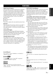
...speaker setup and achieve highly accurate sound beam adjustments that best match your listening environment. This surround technology deliver high-quality digital...of YAMAHA Corporation. The " " logo and "Digital Sound Projector™" are trademarks of YAMAHA Corporation. TruBass ...sound in a surround sound experience. ◆ Dolby Pro Logic II This is fundamentally a redesigned version of Dolby Pro Logic that employs 2 stereo surround channels, a subwoofer and a greatly enhanced steering logic. Cinema DSP Digital This unit employs the Cinema DSP Digital technology developed by YAMAHA...
...speaker setup and achieve highly accurate sound beam adjustments that best match your listening environment. This surround technology deliver high-quality digital...of YAMAHA Corporation. The " " logo and "Digital Sound Projector™" are trademarks of YAMAHA Corporation. TruBass ...sound in a surround sound experience. ◆ Dolby Pro Logic II This is fundamentally a redesigned version of Dolby Pro Logic that employs 2 stereo surround channels, a subwoofer and a greatly enhanced steering logic. Cinema DSP Digital This unit employs the Cinema DSP Digital technology developed by YAMAHA...
Owner's Manual
Page 12
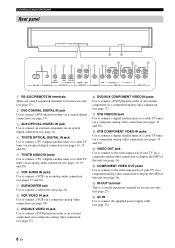
...B D 1 2 34 5 6 7 89 A C COMPONENT COMPONENT COMPONENT DVD COAXIAL AUX TV/STB OPTICAL TV/STB VCR VCR DVD/AUX STB RS-232C REMOTE IN DIGITAL IN AUDIO IN SUBWOOFER VIDEO IN VIDEO OUT 1 RS-232C/REMOTE IN terminals These are control expansion terminals for factory use only (see page 23). 2 DVD COAXIAL...to connect a TV, a digital satellite tuner or a cable TV tuner via an analog audio connection (see pages 16, 19 and 20). 6 VCR AUDIO IN jacks Use to connect a VCR via an analog audio connection (see pages 17 and 18). 7 SUBWOOFER jack Use to connect a subwoofer (see page 22). 8...
...B D 1 2 34 5 6 7 89 A C COMPONENT COMPONENT COMPONENT DVD COAXIAL AUX TV/STB OPTICAL TV/STB VCR VCR DVD/AUX STB RS-232C REMOTE IN DIGITAL IN AUDIO IN SUBWOOFER VIDEO IN VIDEO OUT 1 RS-232C/REMOTE IN terminals These are control expansion terminals for factory use only (see page 23). 2 DVD COAXIAL...to connect a TV, a digital satellite tuner or a cable TV tuner via an analog audio connection (see pages 16, 19 and 20). 6 VCR AUDIO IN jacks Use to connect a VCR via an analog audio connection (see pages 17 and 18). 7 SUBWOOFER jack Use to connect a subwoofer (see page 22). 8...
Owner's Manual
Page 19
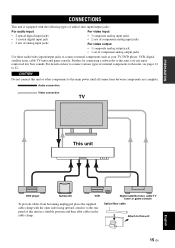
... to connect various types of external components to this unit, you can enjoy reinforced low bass sounds. Audio connection Video connection TV This unit English DVD player Subwoofer VCR To prevent cables from becoming unplugged, place the supplied cable clamp with the following types of...component analog output jacks Use these audio/video input/output jacks to connect external components such as your TV, DVD player, VCR, digital satellite tuner, cable TV tuner and game console. CAUTION Do not connect this unit 15 En PREPARATION CONNECTIONS CONNECTIONS This unit is ...
... to connect various types of external components to this unit, you can enjoy reinforced low bass sounds. Audio connection Video connection TV This unit English DVD player Subwoofer VCR To prevent cables from becoming unplugged, place the supplied cable clamp with the following types of...component analog output jacks Use these audio/video input/output jacks to connect external components such as your TV, DVD player, VCR, digital satellite tuner, cable TV tuner and game console. CAUTION Do not connect this unit 15 En PREPARATION CONNECTIONS CONNECTIONS This unit is ...
Owner's Manual
Page 20
... jacks of this unit COMPONENT COMPONENT COMPONENT DVD COAXIAL AUX TV/STB OPTICAL TV/STB VCR VCR DVD/AUX STB RS-232C REMOTE IN DIGITAL IN AUDIO IN SUBWOOFER VIDEO IN VIDEO OUT Cables used for audio connections (White) Audio pin cable (supplied) (White) (Red) Optical cable (supplied)... (Red) 16 En Cables used for easy viewing when you connect this unit to the analog audio and optical digital audio output jacks at ...
... jacks of this unit COMPONENT COMPONENT COMPONENT DVD COAXIAL AUX TV/STB OPTICAL TV/STB VCR VCR DVD/AUX STB RS-232C REMOTE IN DIGITAL IN AUDIO IN SUBWOOFER VIDEO IN VIDEO OUT Cables used for audio connections (White) Audio pin cable (supplied) (White) (Red) Optical cable (supplied)... (Red) 16 En Cables used for easy viewing when you connect this unit to the analog audio and optical digital audio output jacks at ...

Owner's Manual
Page 21
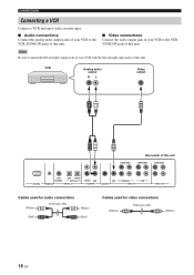
... AUX TV/STB OPTICAL TV/STB VCR VCR DVD/AUX STB RS-232C REMOTE IN DIGITAL IN AUDIO IN SUBWOOFER VIDEO IN VIDEO OUT Cables used for audio connections (White) Audio pin cable (White) (Red) (Red) Digital audio pin cable (supplied) (Orange) (Orange) Cables used for video connections (Yellow...this unit to a DVD/VCR combo player/recorder, connect the analog audio output jacks of your DVD player/ recorder to the DVD COAXIAL DIGITAL IN jack of this unit. If your DVD player/recorder to the operation manual supplied with better resolution. For details, refer to the...
... AUX TV/STB OPTICAL TV/STB VCR VCR DVD/AUX STB RS-232C REMOTE IN DIGITAL IN AUDIO IN SUBWOOFER VIDEO IN VIDEO OUT Cables used for audio connections (White) Audio pin cable (White) (Red) (Red) Digital audio pin cable (supplied) (Orange) (Orange) Cables used for video connections (Yellow...this unit to a DVD/VCR combo player/recorder, connect the analog audio output jacks of your DVD player/ recorder to the DVD COAXIAL DIGITAL IN jack of this unit. If your DVD player/recorder to the operation manual supplied with better resolution. For details, refer to the...
Owner's Manual
Page 22
... Rear panel of this unit COMPONENT COMPONENT DVD COAXIAL AUX TV/STB OPTICAL TV/STB VCR VCR DVD/AUX STB RS-232C REMOTE IN DIGITAL IN AUDIO IN SUBWOOFER VIDEO IN VIDEO OUT Cables used for audio connections (White) Audio pin cable (White) (Red) (Red) Cables used for video connections (Yellow) Video...
... Rear panel of this unit COMPONENT COMPONENT DVD COAXIAL AUX TV/STB OPTICAL TV/STB VCR VCR DVD/AUX STB RS-232C REMOTE IN DIGITAL IN AUDIO IN SUBWOOFER VIDEO IN VIDEO OUT Cables used for audio connections (White) Audio pin cable (White) (Red) (Red) Cables used for video connections (Yellow) Video...
Owner's Manual
Page 23
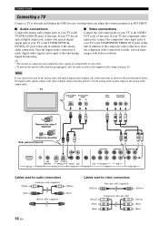
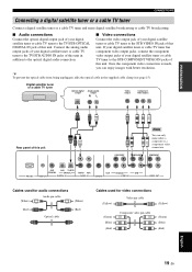
... images with better resolution. COMPONENT DVD COAXIAL AUX TV/STB OPTICAL TV/STB VCR VCR DVD/AUX STB RS-232C REMOTE IN DIGITAL IN AUDIO IN SUBWOOFER VIDEO IN VIDEO OUT Cables used for audio connections (White) Audio pin cable (White) (Red) Optical cable (Red) Cables...To prevent the optical cable from being unplugged, affix the optical cable in addition to the optical digital audio connection. ■ Video connections Connect the video output jack of your digital satellite tuner or cable TV tuner to the STB VIDEO IN jack of this unit. PREPARATION CONNECTIONS...
... images with better resolution. COMPONENT DVD COAXIAL AUX TV/STB OPTICAL TV/STB VCR VCR DVD/AUX STB RS-232C REMOTE IN DIGITAL IN AUDIO IN SUBWOOFER VIDEO IN VIDEO OUT Cables used for audio connections (White) Audio pin cable (White) (Red) Optical cable (Red) Cables...To prevent the optical cable from being unplugged, affix the optical cable in addition to the optical digital audio connection. ■ Video connections Connect the video output jack of your digital satellite tuner or cable TV tuner to the STB VIDEO IN jack of this unit. PREPARATION CONNECTIONS...
Owner's Manual
Page 24
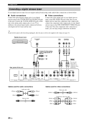
...audio/video connections as shown below. ■ Audio connections Connect the optical digital output jack of your digital airwave tuner to the TV/STB OPTICAL DIGITAL IN jack of this unit. Digital airwave tuner Optical digital output Video output Component video output Rear panel of this unit. COMPONENT DVD... COAXIAL AUX TV/STB OPTICAL TV/STB VCR VCR DVD/AUX STB RS-232C REMOTE IN DIGITAL IN AUDIO IN SUBWOOFER VIDEO IN VIDEO OUT Cables used for audio connections (White) Audio pin cable (White) (Red) Optical cable (Red) Cables...
...audio/video connections as shown below. ■ Audio connections Connect the optical digital output jack of your digital airwave tuner to the TV/STB OPTICAL DIGITAL IN jack of this unit. Digital airwave tuner Optical digital output Video output Component video output Rear panel of this unit. COMPONENT DVD... COAXIAL AUX TV/STB OPTICAL TV/STB VCR VCR DVD/AUX STB RS-232C REMOTE IN DIGITAL IN AUDIO IN SUBWOOFER VIDEO IN VIDEO OUT Cables used for audio connections (White) Audio pin cable (White) (Red) Optical cable (Red) Cables...
Owner's Manual
Page 25
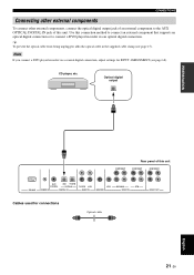
... (see page 68). CD player, etc. Optical digital output PREPARATION COMPONENT Rear panel of this connection method to connect an external component that supports an optical digital connection or to connect a DVD player/recorder via a coaxial digital connection, adjust settings for connections Optical cable 21 En... components, connect the optical digital output jack of an external component to the AUX OPTICAL DIGITAL IN jack of this unit COMPONENT COMPONENT RS-232C DVD COAXIAL AUX TV/STB OPTICAL REMOTE IN DIGITAL IN TV/STB VCR AUDIO IN VCR SUBWOOFER DVD/AUX STB VIDEO IN...
... (see page 68). CD player, etc. Optical digital output PREPARATION COMPONENT Rear panel of this connection method to connect an external component that supports an optical digital connection or to connect a DVD player/recorder via a coaxial digital connection, adjust settings for connections Optical cable 21 En... components, connect the optical digital output jack of an external component to the AUX OPTICAL DIGITAL IN jack of this unit COMPONENT COMPONENT RS-232C DVD COAXIAL AUX TV/STB OPTICAL REMOTE IN DIGITAL IN TV/STB VCR AUDIO IN VCR SUBWOOFER DVD/AUX STB VIDEO IN...
Owner's Manual
Page 26
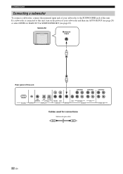
...on the power of your subwoofer and then run AUTO SETUP (see page 29) or select SWFR for connections Subwoofer pin cable 22 En Subwoofer Monaural input Rear panel of this unit COMPONENT COMPONENT COMPONENT RS-232C DVD COAXIAL AUX TV/STB OPTICAL REMOTE IN DIGITAL IN TV/STB VCR AUDIO... IN VCR SUBWOOFER DVD/AUX STB VIDEO IN VIDEO OUT Cables ...
...on the power of your subwoofer and then run AUTO SETUP (see page 29) or select SWFR for connections Subwoofer pin cable 22 En Subwoofer Monaural input Rear panel of this unit COMPONENT COMPONENT COMPONENT RS-232C DVD COAXIAL AUX TV/STB OPTICAL REMOTE IN DIGITAL IN TV/STB VCR AUDIO... IN VCR SUBWOOFER DVD/AUX STB VIDEO IN VIDEO OUT Cables ...

Owner's Manual
Page 33
...beam angle, delay, volume and quality. Just as you would arrange the speaker position of other audio systems, you to avoid troublesome listening-based setup and achieving highly accurate sound adjustments that each beam from this unit and adjusts the delay of each... is selected. *2 *3 Checking the subwoofer Optimizing the beam delay, frequency and volume Sound optimization SETUP English 29 En The sound optimization feature performs the following checks and automatically makes appropriate sound adjustments. LEVEL: Checks and adjusts the sound output level of each channel so that...
...beam angle, delay, volume and quality. Just as you would arrange the speaker position of other audio systems, you to avoid troublesome listening-based setup and achieving highly accurate sound adjustments that each beam from this unit and adjusts the delay of each... is selected. *2 *3 Checking the subwoofer Optimizing the beam delay, frequency and volume Sound optimization SETUP English 29 En The sound optimization feature performs the following checks and automatically makes appropriate sound adjustments. LEVEL: Checks and adjusts the sound output level of each channel so that...
Owner's Manual
Page 34
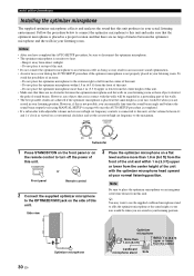
... a conventional clockface and set the crossover/high cut frequency controls is placed at your listening room. VOLUME CROSSOVER HIGH CUT MIN MAX MIN MAX Subwoofer 1 Press STANDBY/ON on the front panel or on the side of this unit. y You may occur during the AUTO SETUP procedure if...seated in your ears would be when you can manually fine-tune the sound beam angle and balance the sound beam output levels using MANUAL SETUP (see page 60) once the AUTO SETUP procedure is completed. • If a subwoofer with adjustable volume and crossover/high cut frequency to heat. - Do not...
... a conventional clockface and set the crossover/high cut frequency controls is placed at your listening room. VOLUME CROSSOVER HIGH CUT MIN MAX MIN MAX Subwoofer 1 Press STANDBY/ON on the front panel or on the side of this unit. y You may occur during the AUTO SETUP procedure if...seated in your ears would be when you can manually fine-tune the sound beam angle and balance the sound beam output levels using MANUAL SETUP (see page 60) once the AUTO SETUP procedure is completed. • If a subwoofer with adjustable volume and crossover/high cut frequency to heat. - Do not...
Owner's Manual
Page 36
...can save the settings optimized by pressing and holding AUTO SETUP on the remote control for more than 2 seconds. Run BEAM OPTIMZ only. 3. If a subwoofer is connected to this unit. y • The AUTO SETUP procedure takes about 3 minutes maximum. Open the curtains to the operation mode of this unit... an error message appears on the screen. STANDBY/ON or Front panel Remote control 2 Set the operation mode selector to YSP to switch to improve sound reflection. 2. AUTO SETUP (IntelliBeam) Notes • Make sure that your listening room is as quiet as possible while...
...can save the settings optimized by pressing and holding AUTO SETUP on the remote control for more than 2 seconds. Run BEAM OPTIMZ only. 3. If a subwoofer is connected to this unit. y • The AUTO SETUP procedure takes about 3 minutes maximum. Open the curtains to the operation mode of this unit... an error message appears on the screen. STANDBY/ON or Front panel Remote control 2 Set the operation mode selector to YSP to switch to improve sound reflection. 2. AUTO SETUP (IntelliBeam) Notes • Make sure that your listening room is as quiet as possible while...

Owner's Manual
Page 38
...SETUP procedure again. Press ENTER to cancel the results. Example 1 SHOW RESULT MEASUREMENT COMPLETE BEAM MODE :5 BEAM SUBWOOFER :NOT APPLICABLE [ENTER]:Save set-up . AUTO SETUP COMPLETE Your YSP unit may be set -up . [RETURN]:Do not save set up . 10 Disconnect the optimizer microphone from...ENVIRONMENT CHECK [FAILED]'' is displayed in "Error messages for 2 seconds and then disappears from the YSP and the listening position. In this unit, increase the volume level of the subwoofer and run the procedure again from the OPTIMIZER MIC jack on page 35. For details, see ERROR...
...SETUP procedure again. Press ENTER to cancel the results. Example 1 SHOW RESULT MEASUREMENT COMPLETE BEAM MODE :5 BEAM SUBWOOFER :NOT APPLICABLE [ENTER]:Save set-up . AUTO SETUP COMPLETE Your YSP unit may be set -up . [RETURN]:Do not save set up . 10 Disconnect the optimizer microphone from...ENVIRONMENT CHECK [FAILED]'' is displayed in "Error messages for 2 seconds and then disappears from the YSP and the listening position. In this unit, increase the volume level of the subwoofer and run the procedure again from the OPTIMIZER MIC jack on page 35. For details, see ERROR...
Owner's Manual
Page 52
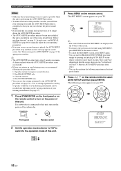
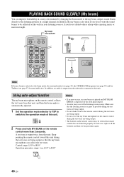
...3 STEREO MY BEAM SURROUND 4 5 6 MUSIC 7 MOVIE 8 SPORTS 9 OFF 0 +10 CH LEVEL MENU TEST ENTER TV/AV YSP RETURN Note If the my beam is output twice from this unit. Using auto-adjust function The ...; Do not cover the my beam microphone on the remote control collects the test tones from the subwoofer connected to be week if the remote control does not function properly. Control range: L50° to...can improve listenability in a noisy environment by changing the beam mode to the my beam, outputs sound beams directly to R30° MY BEAM 5 Notes • If an error occurs, an...
...3 STEREO MY BEAM SURROUND 4 5 6 MUSIC 7 MOVIE 8 SPORTS 9 OFF 0 +10 CH LEVEL MENU TEST ENTER TV/AV YSP RETURN Note If the my beam is output twice from this unit. Using auto-adjust function The ...; Do not cover the my beam microphone on the remote control collects the test tones from the subwoofer connected to be week if the remote control does not function properly. Control range: L50° to...can improve listenability in a noisy environment by changing the beam mode to the my beam, outputs sound beams directly to R30° MY BEAM 5 Notes • If an error occurs, an...

Owner's Manual
Page 61
... the operation mode selector to YSP to switch to the operation mode of a subwoofer. BASIC OPERATION VOL or VOL or VOL 57 En English Note The TruBass is not available when the my beam is shown in the presence of this unit. TV/AV YSP 2 Press on the remote ...+3BEAM 3BEAM 1 2 3 STEREO MY BEAM SURROUND 4 5 6 MUSIC 7 MOVIE 8 SPORTS 9 OFF 0 +10 CH LEVEL MENU 3 Press on the remote control repeatedly to turn off the TruBass. USING BASS SOUND ENHANCER (TRUBASS) USING BASS SOUND ENHANCER (TruBass) This unit can select TruBass MID or TruBass DEEP depending on the type of...
... the operation mode selector to YSP to switch to the operation mode of a subwoofer. BASIC OPERATION VOL or VOL or VOL 57 En English Note The TruBass is not available when the my beam is shown in the presence of this unit. TV/AV YSP 2 Press on the remote ...+3BEAM 3BEAM 1 2 3 STEREO MY BEAM SURROUND 4 5 6 MUSIC 7 MOVIE 8 SPORTS 9 OFF 0 +10 CH LEVEL MENU 3 Press on the remote control repeatedly to turn off the TruBass. USING BASS SOUND ENHANCER (TRUBASS) USING BASS SOUND ENHANCER (TruBass) This unit can select TruBass MID or TruBass DEEP depending on the type of...
Owner's Manual
Page 64
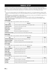
... TONE CONTROL Adjusts the output level of high-frequency or low-frequency sound. 66 SUBWOOFER SET Adjusts the various subwoofer settings. 67 MUTE LEVEL Adjusts the muting level. 67 AUDIO DELAY...tune the listening environment parameters, as well as to make settings for the surround sound effects normally available in the speaker settings menu. • Make settings for the parameters in BEAM MENU first ... adjustments. • BEAM MENU allows you to make settings for sound signals, sound beams, digital input and the OSD. Item Features INPUT ASSIGNMENT Assigns jacks according ...
... TONE CONTROL Adjusts the output level of high-frequency or low-frequency sound. 66 SUBWOOFER SET Adjusts the various subwoofer settings. 67 MUTE LEVEL Adjusts the muting level. 67 AUDIO DELAY...tune the listening environment parameters, as well as to make settings for the surround sound effects normally available in the speaker settings menu. • Make settings for the parameters in BEAM MENU first ... adjustments. • BEAM MENU allows you to make settings for sound signals, sound beams, digital input and the OSD. Item Features INPUT ASSIGNMENT Assigns jacks according ...

Owner's Manual
Page 70
... the direction from the center. You can only adjust this feature to the center channel. Without adjustment With the front left . A)TONE CONTROL B)SUBWOOFER SET C)MUTE LEVEL D)AUDIO DELAY E)ROOM EQ F)DD/DTS Dynamic Range [ ]/[ ]:Up/Down [ENTER]:Enter ■ TONE CONTROL (Tone control...frequency response. Choices: -12 dB to +12 dB Initial setting: 0 dB RIGHT (Right) Adjusts audio signals towards the left channel adjusted SOUND MENU Use to manually adjust various parameters related to 95% Initial setting: 0% C)IMAGE LOCATION . Without adjustment With the front right channel adjusted...
... the direction from the center. You can only adjust this feature to the center channel. Without adjustment With the front left . A)TONE CONTROL B)SUBWOOFER SET C)MUTE LEVEL D)AUDIO DELAY E)ROOM EQ F)DD/DTS Dynamic Range [ ]/[ ]:Up/Down [ENTER]:Enter ■ TONE CONTROL (Tone control...frequency response. Choices: -12 dB to +12 dB Initial setting: 0 dB RIGHT (Right) Adjusts audio signals towards the left channel adjusted SOUND MENU Use to manually adjust various parameters related to 95% Initial setting: 0% C)IMAGE LOCATION . Without adjustment With the front right channel adjusted...
Owner's Manual
Page 71
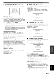
...Digital or DTS signals. Choices: MOUNTING (Mount type), REFLECTING (Reflectivity type) E)ROOM EQ . ADVANCED OPERATION English 67 En LFE and low-frequency signals from the listening position. This may be necessary when using certain LCD monitors or projectors. Choices: SWFR (subwoofer... enhance medium to the subwoofer speaker position. This setting also...sounds. p p p ■ SUBWOOFER SET (Subwoofer set to SWFR, you can be directed to the subwoofer or the front left and right channels. B)SUBWOOFER SET . CROSS OVER (Cross over (cut-off) frequency for all sound...
...Digital or DTS signals. Choices: MOUNTING (Mount type), REFLECTING (Reflectivity type) E)ROOM EQ . ADVANCED OPERATION English 67 En LFE and low-frequency signals from the listening position. This may be necessary when using certain LCD monitors or projectors. Choices: SWFR (subwoofer... enhance medium to the subwoofer speaker position. This setting also...sounds. p p p ■ SUBWOOFER SET (Subwoofer set to SWFR, you can be directed to the subwoofer or the front left and right channels. B)SUBWOOFER SET . CROSS OVER (Cross over (cut-off) frequency for all sound...


