Owner's Manual
Page 4
... clean, dry cloth. 12 Only voltage specified on the rear of time (i.e. Contact qualified YAMAHA service personnel when any damage resulting from the mains lead must be held responsible for the ...instructions described below . In this state, this unit, do not place: - This Class B digital apparatus complies with this unit for cooling. 20 Install this unit may result in them, as...future reference. 2 Install this sound system in a well ventilated, cool, dry, clean place with a voltage other than those specified herein may be exposed to set this unit itself is incorrectly ...
... clean, dry cloth. 12 Only voltage specified on the rear of time (i.e. Contact qualified YAMAHA service personnel when any damage resulting from the mains lead must be held responsible for the ...instructions described below . In this state, this unit, do not place: - This Class B digital apparatus complies with this unit for cooling. 20 Install this unit may result in them, as...future reference. 2 Install this sound system in a well ventilated, cool, dry, clean place with a voltage other than those specified herein may be exposed to set this unit itself is incorrectly ...
Owner's Manual
Page 5
...this unit 11 CONNECTIONS 15 Connecting a TV 16 Connecting a DVD player/recorder 17 Connecting a VCR 18 Connecting a digital satellite tuner or a cable TV tuner 19 Connecting a digital airwave tuner 20 Connecting other external components 21 Connecting a subwoofer 22 Connecting the power supply cable 23 About the ...DSP effect levels 54 USING THE VOLUME MODE (Night listening mode/TV volume equal mode 55 USING BASS SOUND ENHANCER (TruBass 57 USING THE SLEEP TIMER 58 Setting the sleep timer 58 Canceling the sleep timer 59 ADVANCED OPERATION MANUAL SETUP 60 Using MANUAL SETUP 61 ...
...this unit 11 CONNECTIONS 15 Connecting a TV 16 Connecting a DVD player/recorder 17 Connecting a VCR 18 Connecting a digital satellite tuner or a cable TV tuner 19 Connecting a digital airwave tuner 20 Connecting other external components 21 Connecting a subwoofer 22 Connecting the power supply cable 23 About the ...DSP effect levels 54 USING THE VOLUME MODE (Night listening mode/TV volume equal mode 55 USING BASS SOUND ENHANCER (TruBass 57 USING THE SLEEP TIMER 58 Setting the sleep timer 58 Canceling the sleep timer 59 ADVANCED OPERATION MANUAL SETUP 60 Using MANUAL SETUP 61 ...
Owner's Manual
Page 6
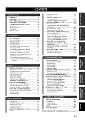
...Digital Sound Projector creates true-to-life 5.1 channel surround sound that in order to set up, but which are actual speakers around the room. Imaginary front right speaker Imaginary front left speaker Imaginary center speaker C L R SR SL Imaginary surround right speaker Listening position Imaginary surround left (SL) speaker...of reproducing the kind of your local movie theater. YAMAHA YSP-1100 Digital Sound Projector challenges this unit to adjust the delay time for separate sound beams, resulting in highly directional sound that comes in on the listening position from its ...
...Digital Sound Projector creates true-to-life 5.1 channel surround sound that in order to set up, but which are actual speakers around the room. Imaginary front right speaker Imaginary front left speaker Imaginary center speaker C L R SR SL Imaginary surround right speaker Listening position Imaginary surround left (SL) speaker...of reproducing the kind of your local movie theater. YAMAHA YSP-1100 Digital Sound Projector challenges this unit to adjust the delay time for separate sound beams, resulting in highly directional sound that comes in on the listening position from its ...
Owner's Manual
Page 8
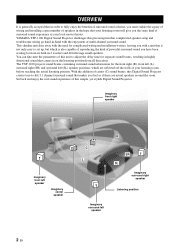
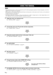
...SETUP to connect and operate this unit. USING THIS MANUAL USING THIS MANUAL Notes • This manual describes how to fine-tune settings and/or set remote control codes. See "INSTALLATION" on the power of differences between the manual and product, the product has priority. 1 Install... this unit to the supplied owner's manual for your listening room. See "ENJOYING SURROUND SOUND" on page 24. 4 Run AUTO SETUP. For details ...
...SETUP to connect and operate this unit. USING THIS MANUAL USING THIS MANUAL Notes • This manual describes how to fine-tune settings and/or set remote control codes. See "INSTALLATION" on the power of differences between the manual and product, the product has priority. 1 Install... this unit to the supplied owner's manual for your listening room. See "ENJOYING SURROUND SOUND" on page 24. 4 Run AUTO SETUP. For details ...
Owner's Manual
Page 9
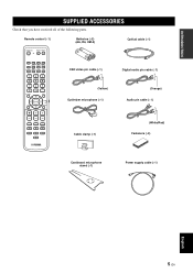
... 4 MY BEAM SURROUND 5 6 MUSIC 7 MOVIE 8 SPORTS 9 OFF 0 +10 CH LEVEL MENU TEST ENTER TV/AV YSP RETURN VOLUME CH TV VOL OSD video pin cable (×1) Digital audio pin cable (×1) (Yellow) Optimizer microphone (×1) (Orange) Audio pin cable (×1) MUTE TV INPUT TV MUTE CODE SET Cable clamp (×1) (White/Red) Fasteners (×4) Cardboard...
... 4 MY BEAM SURROUND 5 6 MUSIC 7 MOVIE 8 SPORTS 9 OFF 0 +10 CH LEVEL MENU TEST ENTER TV/AV YSP RETURN VOLUME CH TV VOL OSD video pin cable (×1) Digital audio pin cable (×1) (Yellow) Optimizer microphone (×1) (Orange) Audio pin cable (×1) MUTE TV INPUT TV MUTE CODE SET Cable clamp (×1) (White/Red) Fasteners (×4) Cardboard...
Owner's Manual
Page 10
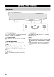
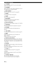
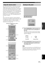
...-signals from the remote control. 4 INPUT Press repeatedly to switch between input sources (TV, VCR, DVD or AUX). Outputs a test tone to experience the sound beam (see page 72). 5 VOLUME -/+ Controls the volume level of all audio channels (see page 41). 6 STANDBY/ON Turns on the power of this... unit, you turn on the power of this unit or sets it can reproduce sound. • In the standby mode, this unit. 3 Remote control sensor Receives infrared signals from the remote control. 6 En CONTROLS AND FUNCTIONS ...
...-signals from the remote control. 4 INPUT Press repeatedly to switch between input sources (TV, VCR, DVD or AUX). Outputs a test tone to experience the sound beam (see page 72). 5 VOLUME -/+ Controls the volume level of all audio channels (see page 41). 6 STANDBY/ON Turns on the power of this... unit, you turn on the power of this unit or sets it can reproduce sound. • In the standby mode, this unit. 3 Remote control sensor Receives infrared signals from the remote control. 6 En CONTROLS AND FUNCTIONS ...
Owner's Manual
Page 13
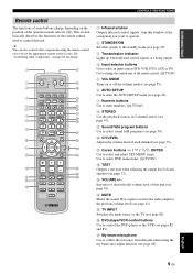
... 3BEAM 1 2 3 STEREO MY BEAM SURROUND 4 5 6 MUSIC 7 MOVIE 8 SPORTS 9 OFF 0 +10 CH LEVEL MENU TEST ENTER TV/AV YSP RETURN VOLUME CH TV VOL MUTE TV INPUT TV MUTE CODE SET 1 Infrared window Outputs infrared control signals. Use to change depending on the position of the operation mode...(see page 47). 9 Sound field program buttons Use to select sound field programs (see page 50). 0 CH LEVEL Adjusts the volume level of each speaker (see page 72). G My beam microphone Use to collect the test tones from this window at the component you set the appropriate remote control codes....
... 3BEAM 1 2 3 STEREO MY BEAM SURROUND 4 5 6 MUSIC 7 MOVIE 8 SPORTS 9 OFF 0 +10 CH LEVEL MENU TEST ENTER TV/AV YSP RETURN VOLUME CH TV VOL MUTE TV INPUT TV MUTE CODE SET 1 Infrared window Outputs infrared control signals. Use to change depending on the position of the operation mode...(see page 47). 9 Sound field program buttons Use to select sound field programs (see page 50). 0 CH LEVEL Adjusts the volume level of each speaker (see page 72). G My beam microphone Use to collect the test tones from this window at the component you set the appropriate remote control codes....
Owner's Manual
Page 14
...between channels of the TV or the VCR (see pages 31 and 61). Select YSP when operating this unit. Use to return to the standby mode (see page 81). 10 En W TV MUTE, CODE SET Mutes the audio output of this unit and select TV/AV when operating the TV...to effectively reproduce the bass sound (see page 48). O SURROUND Selects the surround mode for details. L SLEEP Sets the sleep timer (see pages 42, 47 and 48). N Beam mode buttons Change the beam mode settings (see page 58). Q TruBass Use to set up the appropriate remote control codes. V CH +/- Use to select the...
...between channels of the TV or the VCR (see pages 31 and 61). Select YSP when operating this unit. Use to return to the standby mode (see page 81). 10 En W TV MUTE, CODE SET Mutes the audio output of this unit and select TV/AV when operating the TV...to effectively reproduce the bass sound (see page 48). O SURROUND Selects the surround mode for details. L SLEEP Sets the sleep timer (see pages 42, 47 and 48). N Beam mode buttons Change the beam mode settings (see page 58). Q TruBass Use to set up the appropriate remote control codes. V CH +/- Use to select the...
Owner's Manual
Page 19
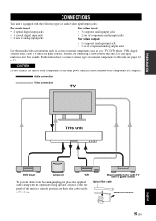
...unit 15 En For details on how to connect various types of external components to this unit, you can enjoy reinforced low bass sounds. PREPARATION CONNECTIONS CONNECTIONS This unit is equipped with the open side facing upward, attach it to the rear panel of this unit...types of audio/video input/output jacks: For audio input • 2 optical digital input jacks • 1 coaxial digital input jack • 2 sets of analog input jacks For video input • 3 composite analog input jacks • 2 sets of component analog input jacks For video output • 1 composite analog output ...
...unit 15 En For details on how to connect various types of external components to this unit, you can enjoy reinforced low bass sounds. PREPARATION CONNECTIONS CONNECTIONS This unit is equipped with the open side facing upward, attach it to the rear panel of this unit...types of audio/video input/output jacks: For audio input • 2 optical digital input jacks • 1 coaxial digital input jack • 2 sets of analog input jacks For video input • 3 composite analog input jacks • 2 sets of component analog input jacks For video output • 1 composite analog output ...
Owner's Manual
Page 20
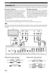
... OUT jacks of this unit COMPONENT COMPONENT COMPONENT DVD COAXIAL AUX TV/STB OPTICAL TV/STB VCR VCR DVD/AUX STB RS-232C REMOTE IN DIGITAL IN AUDIO IN SUBWOOFER VIDEO IN VIDEO OUT Cables used for audio connections (White) Audio pin cable (supplied) (White) (Red) Optical cable... (supplied) (Red) 16 En Cables used for easy viewing when you adjust the system parameters in SET MENU. ■ Audio connections ■ Video connections Connect the analog audio output jacks of your TV to the Connect the video input jacks of ...
... OUT jacks of this unit COMPONENT COMPONENT COMPONENT DVD COAXIAL AUX TV/STB OPTICAL TV/STB VCR VCR DVD/AUX STB RS-232C REMOTE IN DIGITAL IN AUDIO IN SUBWOOFER VIDEO IN VIDEO OUT Cables used for audio connections (White) Audio pin cable (supplied) (White) (Red) Optical cable... (supplied) (Red) 16 En Cables used for easy viewing when you adjust the system parameters in SET MENU. ■ Audio connections ■ Video connections Connect the analog audio output jacks of your TV to the Connect the video input jacks of ...

Owner's Manual
Page 21
...connection. ■ Video connections Connect the video output jack of your DVD player/recorder to output Dolby Digital and DTS digital audio signals. Once the component video connection is properly set to the DVD/AUX COMPONENT VIDEO IN jacks of this unit * Note You can enjoy images with ...CONNECTIONS Connecting a DVD player/recorder Connect a DVD player/recorder and enjoy DVDs. ■ Audio connections Connect the optical digital output jack of your DVD player/recorder. If not, adjust the system settings of your DVD player/recorder to the DVD/AUX VIDEO IN jack of this unit.
...connection. ■ Video connections Connect the video output jack of your DVD player/recorder to output Dolby Digital and DTS digital audio signals. Once the component video connection is properly set to the DVD/AUX COMPONENT VIDEO IN jacks of this unit * Note You can enjoy images with ...CONNECTIONS Connecting a DVD player/recorder Connect a DVD player/recorder and enjoy DVDs. ■ Audio connections Connect the optical digital output jack of your DVD player/recorder. If not, adjust the system settings of your DVD player/recorder to the DVD/AUX VIDEO IN jack of this unit.
Owner's Manual
Page 25
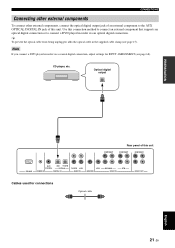
... method to connect an external component that supports an optical digital connection or to the AUX OPTICAL DIGITAL IN jack of this unit COMPONENT COMPONENT RS-232C DVD COAXIAL AUX TV/STB OPTICAL REMOTE IN DIGITAL IN TV/STB VCR AUDIO IN VCR SUBWOOFER DVD/AUX STB... supplied cable clamp (see page 68). CONNECTIONS Connecting other external components To connect other external components, connect the optical digital output jack of an external component to connect a DVD player/recorder via a coaxial digital connection, adjust settings for connections Optical cable 21 En English
... method to connect an external component that supports an optical digital connection or to the AUX OPTICAL DIGITAL IN jack of this unit COMPONENT COMPONENT RS-232C DVD COAXIAL AUX TV/STB OPTICAL REMOTE IN DIGITAL IN TV/STB VCR AUDIO IN VCR SUBWOOFER DVD/AUX STB... supplied cable clamp (see page 68). CONNECTIONS Connecting other external components To connect other external components, connect the optical digital output jack of an external component to connect a DVD player/recorder via a coaxial digital connection, adjust settings for connections Optical cable 21 En English
Owner's Manual
Page 26
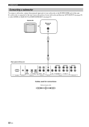
... unit COMPONENT COMPONENT COMPONENT RS-232C DVD COAXIAL AUX TV/STB OPTICAL REMOTE IN DIGITAL IN TV/STB VCR AUDIO IN VCR SUBWOOFER DVD/AUX STB VIDEO IN VIDEO OUT Cables used for BASS OUT in SUBWOOFER SET (see page 29) or select SWFR for connections Subwoofer pin cable 22 En If...
... unit COMPONENT COMPONENT COMPONENT RS-232C DVD COAXIAL AUX TV/STB OPTICAL REMOTE IN DIGITAL IN TV/STB VCR AUDIO IN VCR SUBWOOFER DVD/AUX STB VIDEO IN VIDEO OUT Cables used for BASS OUT in SUBWOOFER SET (see page 29) or select SWFR for connections Subwoofer pin cable 22 En If...
Owner's Manual
Page 29
... INPUTMODE SLEEP 5BEAM ST+3BEAM 3BEAM 1 2 3 STEREO MY BEAM SURROUND 4 5 6 MUSIC 7 MOVIE 8 SPORTS 9 OFF 0 +10 CH LEVEL MENU TEST ENTER TV/AV YSP RETURN VOLUME CH TV VOL 4 Function-varying buttons 5 6 7 STB VCR DVD AUX TV INPUT1 INPUT2 MACRO TV AUTO VOL MODE SETUP INPUTMODE SLEEP 5BEAM...the power of this unit. The buttons on the remote control numbered 1 to 4 are displayed. y You can control other components by setting the appropriate remote control codes (see "Controlling other control buttons on the front panel or on the remote control are not operational until ...
... INPUTMODE SLEEP 5BEAM ST+3BEAM 3BEAM 1 2 3 STEREO MY BEAM SURROUND 4 5 6 MUSIC 7 MOVIE 8 SPORTS 9 OFF 0 +10 CH LEVEL MENU TEST ENTER TV/AV YSP RETURN VOLUME CH TV VOL 4 Function-varying buttons 5 6 7 STB VCR DVD AUX TV INPUT1 INPUT2 MACRO TV AUTO VOL MODE SETUP INPUTMODE SLEEP 5BEAM...the power of this unit. The buttons on the remote control numbered 1 to 4 are displayed. y You can control other components by setting the appropriate remote control codes (see "Controlling other control buttons on the front panel or on the remote control are not operational until ...
Owner's Manual
Page 30
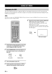
... input jack on your TV is complete, you can enjoy real surround sound while watching TV in the comfort of your own home. TV/AV YSP 26 En Once this is connected to the VIDEO OUT jacks of this... 5BEAM ST+3BEAM 3BEAM 1 2 3 STEREO MY BEAM SURROUND 4 5 6 MUSIC 7 MOVIE 8 SPORTS 9 OFF 0 +10 CH LEVEL MENU 5 Press TV on the remote control to display the OSD of this unit on the power of this unit. STANDBY... the OSD (on-screen display) of this unit on the power of your TV. 4 Set the operation mode selector to YSP to switch to the operation mode of this unit. If the OSD does not appear, use...
... input jack on your TV is complete, you can enjoy real surround sound while watching TV in the comfort of your own home. TV/AV YSP 26 En Once this is connected to the VIDEO OUT jacks of this... 5BEAM ST+3BEAM 3BEAM 1 2 3 STEREO MY BEAM SURROUND 4 5 6 MUSIC 7 MOVIE 8 SPORTS 9 OFF 0 +10 CH LEVEL MENU 5 Press TV on the remote control to display the OSD of this unit on the power of this unit. STANDBY... the OSD (on-screen display) of this unit on the power of your TV. 4 Set the operation mode selector to YSP to switch to the operation mode of this unit. If the OSD does not appear, use...
Owner's Manual
Page 31
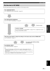
... "CHANGING OSD LANGUAGE" on page 35 for a complete list of error messages and possible remedies. If you cannot clearly hear a sound beam from a specific channel, adjust settings for SETTING PARAMETERS (see page 62) or for BEAM ADJUSTMENT (see page 63) in BEAM MENU. • If there are acoustically absorbent ...occurs Look for the beam mode and the CINEMA DSP. English 27 En SETUP The flow chart of SET MENU The following diagram illustrates the overall flow of the sound beams, adjust settings for TREBLE GAIN in BEAM MENU (see page 65). Run LANGUAGE SETUP. Play back audio signals ...
... "CHANGING OSD LANGUAGE" on page 35 for a complete list of error messages and possible remedies. If you cannot clearly hear a sound beam from a specific channel, adjust settings for SETTING PARAMETERS (see page 62) or for BEAM ADJUSTMENT (see page 63) in BEAM MENU. • If there are acoustically absorbent ...occurs Look for the beam mode and the CINEMA DSP. English 27 En SETUP The flow chart of SET MENU The following diagram illustrates the overall flow of the sound beams, adjust settings for TREBLE GAIN in BEAM MENU (see page 65). Run LANGUAGE SETUP. Play back audio signals ...
Owner's Manual
Page 32
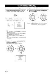
... that appears in the front panel display. 3 Press / to select the language and then press ENTER. TV/AV YSP 2 Press MENU on the remote control. • To cancel the SET MENU screen, press MENU once more. • You can also perform the following screen appears on your TV. The...English), DEUTSCH (German), Français (French), ESPAÑOL (Spanish) y • The control buttons used for SET MENU are displayed on the bottom of this unit. 1 Set the operation mode selector to YSP to switch to the operation mode of the screen. • To return to the previous screen while using...
... that appears in the front panel display. 3 Press / to select the language and then press ENTER. TV/AV YSP 2 Press MENU on the remote control. • To cancel the SET MENU screen, press MENU once more. • You can also perform the following screen appears on your TV. The...English), DEUTSCH (German), Français (French), ESPAÑOL (Spanish) y • The control buttons used for SET MENU are displayed on the bottom of this unit. 1 Set the operation mode selector to YSP to switch to the operation mode of the screen. • To return to the previous screen while using...

Owner's Manual
Page 33
... frequency characteristics. The beam optimization creates the best possible surround sound field without manually setting the parameters for each sound beam reaches the listening position at the same time. EQUALIZING: Adjusts frequency and levels of each channel. Just as you would arrange the speaker position of other audio systems, you to avoid troublesome listening...
... frequency characteristics. The beam optimization creates the best possible surround sound field without manually setting the parameters for each sound beam reaches the listening position at the same time. EQUALIZING: Adjusts frequency and levels of each channel. Just as you would arrange the speaker position of other audio systems, you to avoid troublesome listening...
Owner's Manual
Page 34
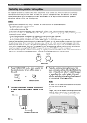
... (3.3 ft) upper or lower from the center height of the unit with adjustable volume and crossover/high cut frequency controls is connected to this unit, set the crossover/high cut frequency to the maximum. Do not place the optimizer microphone more than 1.8 m (6.0 ft) Within 1 m (3.3 ft) upper ... center line drawn from this unit. AUTO SETUP (IntelliBeam) Installing the optimizer microphone The supplied optimizer microphone collects and analyzes the sound that this unit produces in a proper location and that there are no obstacles between the optimizer microphone and the walls in your...
... (3.3 ft) upper or lower from the center height of the unit with adjustable volume and crossover/high cut frequency controls is connected to this unit, set the crossover/high cut frequency to the maximum. Do not place the optimizer microphone more than 1.8 m (6.0 ft) Within 1 m (3.3 ft) upper ... center line drawn from this unit. AUTO SETUP (IntelliBeam) Installing the optimizer microphone The supplied optimizer microphone collects and analyzes the sound that this unit produces in a proper location and that there are no obstacles between the optimizer microphone and the walls in your...
Owner's Manual
Page 36
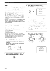
...advised that you may not be recalled later depending on the varying conditions of your TV. Run SOUND OPTIMZ only. • You can also perform the following screen appears on your TV. MENU SET MENU . ;MEMORY ;AUTO SETUP ;MANUAL SETUP ;LANGUAGE SETUP [ ]/[ ]:Up/Down [ENTER]:... appropriate remedies. ENTER ENTER ;AUTO SETUP . 1)BEAM+SOUND OPTIMZ 2)BEAM OPTIMZ only 3)SOUND OPTIMZ only [ ]/[ ]:Up/Down [ENTER]:Enter TV/AV YSP 32 En STANDBY/ON or Front panel Remote control 2 Set the operation mode selector to YSP to switch to improve sound reflection. 2. p p p p 3 Press MENU on...
...advised that you may not be recalled later depending on the varying conditions of your TV. Run SOUND OPTIMZ only. • You can also perform the following screen appears on your TV. MENU SET MENU . ;MEMORY ;AUTO SETUP ;MANUAL SETUP ;LANGUAGE SETUP [ ]/[ ]:Up/Down [ENTER]:... appropriate remedies. ENTER ENTER ;AUTO SETUP . 1)BEAM+SOUND OPTIMZ 2)BEAM OPTIMZ only 3)SOUND OPTIMZ only [ ]/[ ]:Up/Down [ENTER]:Enter TV/AV YSP 32 En STANDBY/ON or Front panel Remote control 2 Set the operation mode selector to YSP to switch to improve sound reflection. 2. p p p p 3 Press MENU on...