
Owner's Manual
Page 2
... prong are provided for replacement of important operating and maintenance (servicing) instructions in accordance with dry cloth. 7 Do not block any heat sources such as power-supply cord or plug is intended to alert you to the presence of the obsolete outlet. 10 Protect the... power supply cable from being walked on or pinched particularly at plugs, convenience receptacles, and the point where they exit from tip-over. 13 Unplug this ...
... prong are provided for replacement of important operating and maintenance (servicing) instructions in accordance with dry cloth. 7 Do not block any heat sources such as power-supply cord or plug is intended to alert you to the presence of the obsolete outlet. 10 Protect the... power supply cable from being walked on or pinched particularly at plugs, convenience receptacles, and the point where they exit from tip-over. 13 Unplug this ...
Owner's Manual
Page 3
IMPORTANT SAFETY INSTRUCTIONS FCC INFORMATION (for Class "B" digital devices. Modifications not expressly approved by YAMAHA Corporation of your FCC authorization to accessories and/or another product use this manual, meets FCC requirements. In the case of this product...in this product in to use of radio or TV interference, relocate/reorient the antenna. Utilize power outlets that is found to comply with FCC regulations does not guarantee that lets the sound come through loud and clear without affecting your authority, granted by the interference. If you to...
IMPORTANT SAFETY INSTRUCTIONS FCC INFORMATION (for Class "B" digital devices. Modifications not expressly approved by YAMAHA Corporation of your FCC authorization to accessories and/or another product use this manual, meets FCC requirements. In the case of this product...in this product in to use of radio or TV interference, relocate/reorient the antenna. Utilize power outlets that is found to comply with FCC regulations does not guarantee that lets the sound come through loud and clear without affecting your authority, granted by the interference. If you to...
Owner's Manual
Page 4
... fire, damage to modify or fix this unit with a higher voltage than specified is needed. YAMAHA will form when the surrounding temperature changes suddenly. This Class B digital apparatus complies with the same or equivalent type. CAUTION: READ THIS BEFORE OPERATING THIS UNIT. 1...this unit. - Contact qualified YAMAHA service personnel when any damage resulting from cold to read this unit - vacation), disconnect the AC power plug from the outlet, then leave the unit alone. 19 When using the unit for future reference. 2 Install this sound system in a well ventilated...
... fire, damage to modify or fix this unit with a higher voltage than specified is needed. YAMAHA will form when the surrounding temperature changes suddenly. This Class B digital apparatus complies with the same or equivalent type. CAUTION: READ THIS BEFORE OPERATING THIS UNIT. 1...this unit. - Contact qualified YAMAHA service personnel when any damage resulting from cold to read this unit - vacation), disconnect the AC power plug from the outlet, then leave the unit alone. 19 When using the unit for future reference. 2 Install this sound system in a well ventilated...
Owner's Manual
Page 5
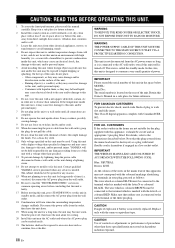
...TV 16 Connecting a DVD player/recorder 17 Connecting a VCR 18 Connecting a digital satellite tuner or a cable TV tuner 19 Connecting a digital airwave tuner 20 Connecting other external components 21 Connecting a subwoofer 22 Connecting the power supply cable 23 About the RS-232C/REMOTE IN/IR-OUT terminals 23 ... programs 54 Adjusting CINEMA DSP effect levels 54 USING THE VOLUME MODE (Night listening mode/TV volume equal mode 55 USING BASS SOUND ENHANCER (TruBass 57 USING THE SLEEP TIMER 58 Setting the sleep timer 58 Canceling the sleep timer 59 ADVANCED OPERATION MANUAL SETUP...
...TV 16 Connecting a DVD player/recorder 17 Connecting a VCR 18 Connecting a digital satellite tuner or a cable TV tuner 19 Connecting a digital airwave tuner 20 Connecting other external components 21 Connecting a subwoofer 22 Connecting the power supply cable 23 About the RS-232C/REMOTE IN/IR-OUT terminals 23 ... programs 54 Adjusting CINEMA DSP effect levels 54 USING THE VOLUME MODE (Night listening mode/TV volume equal mode 55 USING BASS SOUND ENHANCER (TruBass 57 USING THE SLEEP TIMER 58 Setting the sleep timer 58 Canceling the sleep timer 59 ADVANCED OPERATION MANUAL SETUP...
Owner's Manual
Page 6
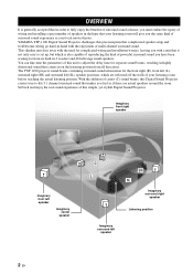
YAMAHA YSP-1100 Digital Sound Projector challenges this Digital Sound Projector creates true-to adjust the delay time for separate sound beams, resulting in highly directional sound that comes in -hand with a unit that in order to set up, but which are actual speakers around the room. The YSP-1100 projects sound beams containing surround sound information for the front right (R), front left (L), surround right (SR) and...
YAMAHA YSP-1100 Digital Sound Projector challenges this Digital Sound Projector creates true-to adjust the delay time for separate sound beams, resulting in highly directional sound that comes in -hand with a unit that in order to set up, but which are actual speakers around the room. The YSP-1100 projects sound beams containing surround sound information for the front right (R), front left (L), surround right (SR) and...
Owner's Manual
Page 8
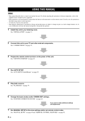
.... See "MANUAL SETUP" on page 60 and "REMOTE CONTROL FEATURES" on page 29. 5 Play back a source. In case of improvements, etc. See "ENJOYING SURROUND SOUND" on the power of external components, refer to the supplied owner's manual for the component. • Some operations can be performed by using remote control operation. •...
.... See "MANUAL SETUP" on page 60 and "REMOTE CONTROL FEATURES" on page 29. 5 Play back a source. In case of improvements, etc. See "ENJOYING SURROUND SOUND" on the power of external components, refer to the supplied owner's manual for the component. • Some operations can be performed by using remote control operation. •...
Owner's Manual
Page 9
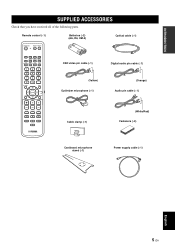
...3BEAM 3 STEREO 4 MY BEAM SURROUND 5 6 MUSIC 7 MOVIE 8 SPORTS 9 OFF 0 +10 CH LEVEL MENU TEST ENTER TV/AV YSP RETURN VOLUME CH TV VOL OSD video pin cable (×1) Digital audio pin cable (×1) (Yellow) Optimizer microphone (×1) (Orange) Audio pin cable (×1)... MUTE TV INPUT TV MUTE CODE SET Cable clamp (×1) (White/Red) Fasteners (×4) Cardboard microphone stand (×1) Power...
...3BEAM 3 STEREO 4 MY BEAM SURROUND 5 6 MUSIC 7 MOVIE 8 SPORTS 9 OFF 0 +10 CH LEVEL MENU TEST ENTER TV/AV YSP RETURN VOLUME CH TV VOL OSD video pin cable (×1) Digital audio pin cable (×1) (Yellow) Optimizer microphone (×1) (Orange) Audio pin cable (×1)... MUTE TV INPUT TV MUTE CODE SET Cable clamp (×1) (White/Red) Fasteners (×4) Cardboard microphone stand (×1) Power...
Owner's Manual
Page 10
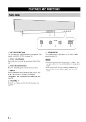
Notes • When you turn on the power of power in order to receive infrared-signals from the remote control. 4 INPUT Press repeatedly to switch between input sources (TV, VCR, DVD or AUX). Outputs a test tone to experience the sound beam (see page 72). 5 VOLUME -/+ Controls the volume level of all audio ...channels (see page 41). 6 STANDBY/ON Turns on the power of this unit, you will hear a click and there will be used to run AUTO...
Notes • When you turn on the power of power in order to receive infrared-signals from the remote control. 4 INPUT Press repeatedly to switch between input sources (TV, VCR, DVD or AUX). Outputs a test tone to experience the sound beam (see page 72). 5 VOLUME -/+ Controls the volume level of all audio ...channels (see page 41). 6 STANDBY/ON Turns on the power of this unit, you will hear a click and there will be used to run AUTO...
Owner's Manual
Page 12
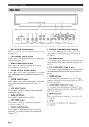
...F 0 B D 1 2 34 5 6 7 89 A C COMPONENT COMPONENT COMPONENT DVD COAXIAL AUX TV/STB OPTICAL TV/STB VCR VCR DVD/AUX STB RS-232C REMOTE IN DIGITAL IN AUDIO IN SUBWOOFER VIDEO IN VIDEO OUT 1 RS-232C/REMOTE IN terminals These are control expansion terminals for factory use only (see page 23... video input jack of this unit (see pages 19 and 20). B STB COMPONENT VIDEO IN jacks Use to connect the supplied power supply cable (see page 17). F AC IN Use to connect a digital satellite tuner or a cable TV tuner via a component analog video connection (see page 23). 8 En
...F 0 B D 1 2 34 5 6 7 89 A C COMPONENT COMPONENT COMPONENT DVD COAXIAL AUX TV/STB OPTICAL TV/STB VCR VCR DVD/AUX STB RS-232C REMOTE IN DIGITAL IN AUDIO IN SUBWOOFER VIDEO IN VIDEO OUT 1 RS-232C/REMOTE IN terminals These are control expansion terminals for factory use only (see page 23... video input jack of this unit (see pages 19 and 20). B STB COMPONENT VIDEO IN jacks Use to connect the supplied power supply cable (see page 17). F AC IN Use to connect a digital satellite tuner or a cable TV tuner via a component analog video connection (see page 23). 8 En
Owner's Manual
Page 13
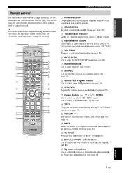
...selector (S). STANDBY/ON POWER POWER AV TV STB VCR DVD AUX TV INPUT1 INPUT2 MACRO TV AUTO VOL MODE SETUP INPUTMODE SLEEP 5BEAM ST+3BEAM 3BEAM 1 2 3 STEREO MY BEAM SURROUND 4 5 6 MUSIC 7 MOVIE 8 SPORTS 9 OFF 0 +10 CH LEVEL MENU TEST ENTER TV/AV YSP RETURN VOLUME CH TV VOL MUTE TV... to enter numbers. (S:TV/AV) 8 STEREO Use the playback sources in 2-channel stereo (see page 47). 9 Sound field program buttons Use to select sound field programs (see page 50). 0 CH LEVEL Adjusts the volume level of each speaker (see page 72). Use to change depending on page 82 for details.
...selector (S). STANDBY/ON POWER POWER AV TV STB VCR DVD AUX TV INPUT1 INPUT2 MACRO TV AUTO VOL MODE SETUP INPUTMODE SLEEP 5BEAM ST+3BEAM 3BEAM 1 2 3 STEREO MY BEAM SURROUND 4 5 6 MUSIC 7 MOVIE 8 SPORTS 9 OFF 0 +10 CH LEVEL MENU TEST ENTER TV/AV YSP RETURN VOLUME CH TV VOL MUTE TV... to enter numbers. (S:TV/AV) 8 STEREO Use the playback sources in 2-channel stereo (see page 47). 9 Sound field program buttons Use to select sound field programs (see page 50). 0 CH LEVEL Adjusts the volume level of each speaker (see page 72). Use to change depending on page 82 for details.
Owner's Manual
Page 14
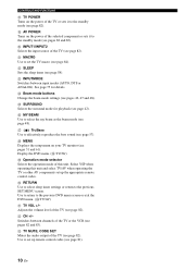
Q TruBass Use to effectively reproduce the bass sound (see page 82). T RETURN Use to select sleep timer settings or return to ...See page 75 for playback (see page 48). V CH +/- CONTROLS AND FUNCTIONS H TV POWER Turns on the power of the TV or sets it to the standby mode (see page 82). Select YSP when operating this unit. M INPUTMODE Switches between channels ... the selected component or sets it to the standby mode (see pages 82 and 83). I AV POWER Turns on the power of this unit and select TV/AV when operating the TV or other AV components set up the ...
Q TruBass Use to effectively reproduce the bass sound (see page 82). T RETURN Use to select sleep timer settings or return to ...See page 75 for playback (see page 48). V CH +/- CONTROLS AND FUNCTIONS H TV POWER Turns on the power of the TV or sets it to the standby mode (see page 82). Select YSP when operating this unit. M INPUTMODE Switches between channels ... the selected component or sets it to the standby mode (see pages 82 and 83). I AV POWER Turns on the power of this unit and select TV/AV when operating the TV or other AV components set up the ...

Owner's Manual
Page 18
... Fasteners Peel off the film from each of the four supplied fasteners and then secure them to a dirty or wet surface will weaken the sticking power of the tape, and this unit may fall as a result. 14 En before securing the fasteners. This unit may fall over and cause injury. •...
... Fasteners Peel off the film from each of the four supplied fasteners and then secure them to a dirty or wet surface will weaken the sticking power of the tape, and this unit may fall as a result. 14 En before securing the fasteners. This unit may fall over and cause injury. •...
Owner's Manual
Page 19
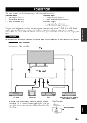
..., place the supplied cable clamp with the following types of audio/video input/output jacks: For audio input • 2 optical digital input jacks • 1 coaxial digital input jack • 2 sets of analog input jacks For video input • 3 composite analog input jacks • 2 ... cable clamp. CAUTION Do not connect this unit, you can enjoy reinforced low bass sounds. Further, by connecting a subwoofer to this unit or other components to the main power until all connections between components are complete. PREPARATION CONNECTIONS CONNECTIONS This unit is equipped with...
..., place the supplied cable clamp with the following types of audio/video input/output jacks: For audio input • 2 optical digital input jacks • 1 coaxial digital input jack • 2 sets of analog input jacks For video input • 3 composite analog input jacks • 2 ... cable clamp. CAUTION Do not connect this unit, you can enjoy reinforced low bass sounds. Further, by connecting a subwoofer to this unit or other components to the main power until all connections between components are complete. PREPARATION CONNECTIONS CONNECTIONS This unit is equipped with...
Owner's Manual
Page 26
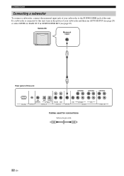
If a subwoofer is connected to this unit, turn on the power of your subwoofer to the SUBWOOFER jack of this unit COMPONENT COMPONENT COMPONENT RS-232C DVD COAXIAL AUX TV/STB OPTICAL REMOTE IN DIGITAL IN TV/STB VCR AUDIO IN VCR SUBWOOFER DVD/AUX STB VIDEO IN VIDEO OUT Cables used for...
If a subwoofer is connected to this unit, turn on the power of your subwoofer to the SUBWOOFER jack of this unit COMPONENT COMPONENT COMPONENT RS-232C DVD COAXIAL AUX TV/STB OPTICAL REMOTE IN DIGITAL IN TV/STB VCR AUDIO IN VCR SUBWOOFER DVD/AUX STB VIDEO IN VIDEO OUT Cables used for...
Owner's Manual
Page 27
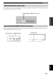
PREPARATION CONNECTIONS Connecting the power supply cable Once all other connections are control expansion terminals for factory use only. To the AC outlet About the RS-232C/REMOTE IN/IR-... terminals The RS-232C, REMOTE IN and IR-OUT terminals do not support normal external component connections. These are complete, plug one end of the power supply cable into the AC IN terminal of this unit and then plug the other end into the AC wall outlet. RS-232C terminal REMOTE...
PREPARATION CONNECTIONS Connecting the power supply cable Once all other connections are control expansion terminals for factory use only. To the AC outlet About the RS-232C/REMOTE IN/IR-... terminals The RS-232C, REMOTE IN and IR-OUT terminals do not support normal external component connections. These are complete, plug one end of the power supply cable into the AC IN terminal of this unit and then plug the other end into the AC wall outlet. RS-232C terminal REMOTE...
Owner's Manual
Page 29
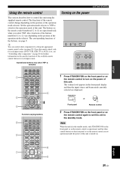
... INPUTMODE SLEEP 5BEAM ST+3BEAM 3BEAM 1 2 3 STEREO MY BEAM SURROUND 4 5 6 MUSIC 7 MOVIE 8 SPORTS 9 OFF 0 +10 CH LEVEL MENU TEST ENTER TV/AV YSP RETURN VOLUME CH TV VOL 8 9 Turning on the power INPUT VOLUME + STANDBY/ON STANDBY/ON POWER POWER AV TV STB VCR DVD AUX TV INPUT1 INPUT2 MACRO TV 1 Press STANDBY/ON on the...
... INPUTMODE SLEEP 5BEAM ST+3BEAM 3BEAM 1 2 3 STEREO MY BEAM SURROUND 4 5 6 MUSIC 7 MOVIE 8 SPORTS 9 OFF 0 +10 CH LEVEL MENU TEST ENTER TV/AV YSP RETURN VOLUME CH TV VOL 8 9 Turning on the power INPUT VOLUME + STANDBY/ON STANDBY/ON POWER POWER AV TV STB VCR DVD AUX TV INPUT1 INPUT2 MACRO TV 1 Press STANDBY/ON on the...
Owner's Manual
Page 30
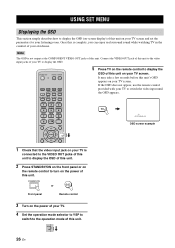
Note The OSD is complete, you can enjoy real surround sound while watching TV in the comfort of your own home. STANDBY/ON or Front panel Remote control 3 Turn on your TV screen. STANDBY/ON POWER POWER AV TV STB VCR DVD AUX TV INPUT1 INPUT2 MACRO TV AUTO VOL MODE SETUP INPUTMODE ... ST+3BEAM 3BEAM 1 2 3 STEREO MY BEAM SURROUND 4 5 6 MUSIC 7 MOVIE 8 SPORTS 9 OFF 0 +10 CH LEVEL MENU 5 Press TV on the remote control to display the OSD of this unit on the power of your TV. 4 Set the operation mode selector to YSP to switch to the operation mode of this unit. If the OSD...
Note The OSD is complete, you can enjoy real surround sound while watching TV in the comfort of your own home. STANDBY/ON or Front panel Remote control 3 Turn on your TV screen. STANDBY/ON POWER POWER AV TV STB VCR DVD AUX TV INPUT1 INPUT2 MACRO TV AUTO VOL MODE SETUP INPUTMODE ... ST+3BEAM 3BEAM 1 2 3 STEREO MY BEAM SURROUND 4 5 6 MUSIC 7 MOVIE 8 SPORTS 9 OFF 0 +10 CH LEVEL MENU 5 Press TV on the remote control to display the OSD of this unit on the power of your TV. 4 Set the operation mode selector to YSP to switch to the operation mode of this unit. If the OSD...
Owner's Manual
Page 34
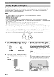
...from the center Cardboard microphone stand Sofa STANDBY/ON or Front panel Remote control 2 Connect the supplied optimizer microphone to turn off the power of this unit. VOLUME CROSSOVER HIGH CUT MIN MAX MIN MAX Subwoofer 1 Press STANDBY/ON on the front panel or on the ... optimizer microphone is placed in a proper location and that there are no obstacles between the optimizer microphone and the walls in an inaccurate sound optimization. • An error may want to use the supplied cardboard microphone stand to affix the optimizer microphone at your listening position. ...
...from the center Cardboard microphone stand Sofa STANDBY/ON or Front panel Remote control 2 Connect the supplied optimizer microphone to turn off the power of this unit. VOLUME CROSSOVER HIGH CUT MIN MAX MIN MAX Subwoofer 1 Press STANDBY/ON on the front panel or on the ... optimizer microphone is placed in a proper location and that there are no obstacles between the optimizer microphone and the walls in an inaccurate sound optimization. • An error may want to use the supplied cardboard microphone stand to affix the optimizer microphone at your listening position. ...

Owner's Manual
Page 35
...the optimizer microphone is firmly connected to this unit performs both of the beam optimization and sound optimization procedures. ■ Assembling the supplied cardboard microphone stand You will find three separate...SETUP on top of the circular-shaped part. INPUT VOLUME + STANDBY/ON STANDBY/ON POWER POWER AV TV STB VCR DVD AUX TV INPUT1 INPUT2 MACRO TV AUTO VOL MODE SETUP INPUTMODE... MY BEAM SURROUND 4 5 6 MUSIC 7 MOVIE 8 SPORTS 9 OFF 0 +10 CH LEVEL MENU TEST ENTER TV/AV YSP RETURN English 31 En In this case, this unit and properly placed in your listening room...
...the optimizer microphone is firmly connected to this unit performs both of the beam optimization and sound optimization procedures. ■ Assembling the supplied cardboard microphone stand You will find three separate...SETUP on top of the circular-shaped part. INPUT VOLUME + STANDBY/ON STANDBY/ON POWER POWER AV TV STB VCR DVD AUX TV INPUT1 INPUT2 MACRO TV AUTO VOL MODE SETUP INPUTMODE... MY BEAM SURROUND 4 5 6 MUSIC 7 MOVIE 8 SPORTS 9 OFF 0 +10 CH LEVEL MENU TEST ENTER TV/AV YSP RETURN English 31 En In this case, this unit and properly placed in your listening room...
Owner's Manual
Page 36
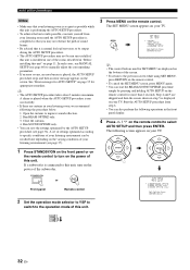
... your listening environment can be run successfully if this unit is installed in one of the rooms described in "Before installing this unit" on the power of the subwoofer. If a subwoofer is connected to this unit, turn on the remote control to select AUTO SETUP and then press ENTER. AUTO... the AUTO SETUP procedure stops and then an error message appears on your TV. ENTER ENTER ;AUTO SETUP . 1)BEAM+SOUND OPTIMZ 2)BEAM OPTIMZ only 3)SOUND OPTIMZ only [ ]/[ ]:Up/Down [ENTER]:Enter TV/AV YSP 32 En Step 4 and 5 are displayed on the bottom of this unit. In such cases, run MANUAL SETUP (...
... your listening environment can be run successfully if this unit is installed in one of the rooms described in "Before installing this unit" on the power of the subwoofer. If a subwoofer is connected to this unit, turn on the remote control to select AUTO SETUP and then press ENTER. AUTO... the AUTO SETUP procedure stops and then an error message appears on your TV. ENTER ENTER ;AUTO SETUP . 1)BEAM+SOUND OPTIMZ 2)BEAM OPTIMZ only 3)SOUND OPTIMZ only [ ]/[ ]:Up/Down [ENTER]:Enter TV/AV YSP 32 En Step 4 and 5 are displayed on the bottom of this unit. In such cases, run MANUAL SETUP (...


