

Owner's Manual
Page 2
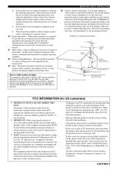
...where they may cause hazards. 7 Water and Moisture - Never spill liquid of the product should follow the manufacturer's instructions, and should use a mounting accessory recommended by the manufacturer. 9 A product and cart combination should be moved with arrowhead symbol, within an equilateral triangle,...; All the safety and operating instructions should still fail to fit, contact your electrician to overturn. 10 Ventilation - Do not use attachments not recommended by items placed upon or against them might be adhered to qualified service personnel. 19 Damage Requiring Service - ...
...where they may cause hazards. 7 Water and Moisture - Never spill liquid of the product should follow the manufacturer's instructions, and should use a mounting accessory recommended by the manufacturer. 9 A product and cart combination should be moved with arrowhead symbol, within an equilateral triangle,...; All the safety and operating instructions should still fail to fit, contact your electrician to overturn. 10 Ventilation - Do not use attachments not recommended by items placed upon or against them might be adhered to qualified service personnel. 19 Damage Requiring Service - ...
Owner's Manual
Page 3
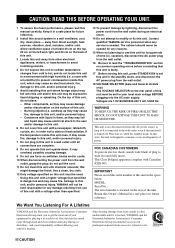
... that is found to distribute this product is being affected by the manufacturer. 23 Heat - Adjust only those products distributed by Yamaha Corporation of radio or TV interference, relocate/reorient the antenna. NATIONAL ELECTRICAL CODE ANTENNA LEAD IN WIRE ANTENNA DISCHARGE UNIT (NEC ..., stoves, or other hazards. 21 Safety Check - If these requirements provides a reasonable level of assurance that your FCC authorization to use of cable entry as close to CATV system installer: This reminder is in fire, electric shock, or other products (including amplifiers) that...
... that is found to distribute this product is being affected by the manufacturer. 23 Heat - Adjust only those products distributed by Yamaha Corporation of radio or TV interference, relocate/reorient the antenna. NATIONAL ELECTRICAL CODE ANTENNA LEAD IN WIRE ANTENNA DISCHARGE UNIT (NEC ..., stoves, or other hazards. 21 Safety Check - If these requirements provides a reasonable level of assurance that your FCC authorization to use of cable entry as close to CATV system installer: This reminder is in fire, electric shock, or other products (including amplifiers) that...
Owner's Manual
Page 4
... objects (i.e. Containers with a newspaper, tablecloth, curtain, etc. this unit in the space below. We Want You Listening For A Lifetime YAMAHA and the Electronic Industries Association's Consumer Electronics Group want you to avoid prolonged exposure from excessive volume levels. One that this unit is dangerous...the AC main supply. This unit is located on switches, knobs and/or cords. 10 When disconnecting the power cord from use this unit, press STANDBY/ON to set for long periods of your sensitive hearing. MODEL: Serial No.: The serial number is...
... objects (i.e. Containers with a newspaper, tablecloth, curtain, etc. this unit in the space below. We Want You Listening For A Lifetime YAMAHA and the Electronic Industries Association's Consumer Electronics Group want you to avoid prolonged exposure from excessive volume levels. One that this unit is dangerous...the AC main supply. This unit is located on switches, knobs and/or cords. 10 When disconnecting the power cord from use this unit, press STANDBY/ON to set for long periods of your sensitive hearing. MODEL: Serial No.: The serial number is...
Owner's Manual
Page 5
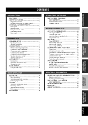
...FEATURES 2 GETTING STARTED 3 Supplied accessories 3 Installing batteries in the remote control 3 CONTROLS AND FUNCTIONS 4 Front panel 4 Remote control 6 Using the remote control 7 Front panel display 8 Rear panel 10 PREPARATION SPEAKER SETUP 11 Speaker placement 11 Speaker connections 12 CONNECTIONS 15 Before ...Turning on the power 23 AUTO SETUP 24 Introduction 24 Optimizer microphone setup 24 Starting the setup 25 BASIC SETUP 28 Using BASIC setup 28 BASIC OPERATION PLAYBACK 30 Basic operations 30 Selecting sound field programs 32 Selecting input modes 34 TUNING 36...
...FEATURES 2 GETTING STARTED 3 Supplied accessories 3 Installing batteries in the remote control 3 CONTROLS AND FUNCTIONS 4 Front panel 4 Remote control 6 Using the remote control 7 Front panel display 8 Rear panel 10 PREPARATION SPEAKER SETUP 11 Speaker placement 11 Speaker connections 12 CONNECTIONS 15 Before ...Turning on the power 23 AUTO SETUP 24 Introduction 24 Optimizer microphone setup 24 Starting the setup 25 BASIC SETUP 28 Using BASIC setup 28 BASIC OPERATION PLAYBACK 30 Basic operations 30 Selecting sound field programs 32 Selecting input modes 34 TUNING 36...
Owner's Manual
Page 6
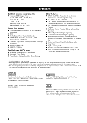
...9670; 40-Station Random Access Preset Tuning ◆ Automatic Preset Tuning ◆ Preset Station Shifting Capability (Preset Editing) Other features ◆ YPAO: YAMAHA Parametric Room Acoustic Optimizer for Automatic Speaker Setup ◆ 192-kHz/24-bit D/A Converter ◆ "SET MENU" which Provides You with Items for ...for Your Audio/Video System ◆ 6 or 8-channel External Decoder Input for your operation. • Some operations can be performed by using either the buttons on the main unit or on the remote control is given in parentheses. • This manual is printed prior to ...
...9670; 40-Station Random Access Preset Tuning ◆ Automatic Preset Tuning ◆ Preset Station Shifting Capability (Preset Editing) Other features ◆ YPAO: YAMAHA Parametric Room Acoustic Optimizer for Automatic Speaker Setup ◆ 192-kHz/24-bit D/A Converter ◆ "SET MENU" which Provides You with Items for ...for Your Audio/Video System ◆ 6 or 8-channel External Decoder Input for your operation. • Some operations can be performed by using either the buttons on the main unit or on the remote control is given in parentheses. • This manual is printed prior to ...
Owner's Manual
Page 7
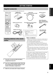
...place it on the inside of the battery compartment. 3 Slide the cover back until it snaps into contact with new ones. • Do not use old batteries together with clothing, etc. the operation range of the remote control decreases, the indicator does not flash or its light becomes dim. •...; Do not use different types of batteries (such as these different types of batteries may have the same shape and color. • If the batteries have been cleared...
...place it on the inside of the battery compartment. 3 Slide the cover back until it snaps into contact with new ones. • Do not use old batteries together with clothing, etc. the operation range of the remote control decreases, the indicator does not flash or its light becomes dim. •...; Do not use different types of batteries (such as these different types of batteries may have the same shape and color. • If the batteries have been cleared...
Owner's Manual
Page 9
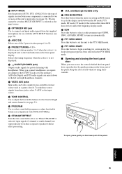
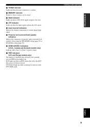
...(2-channel or multi-channel) are output directly from a portable external source such as the input source. C OPTIMIZER MIC jack Use to connect and input audio signals from these controls. I PROGRAM Use to tune in the front panel display. To open the door by gently pressing on the lower part of the... panel. To reproduce source signals from the supplied microphone for use the controls behind the front panel door, open , press gently on the lower part of the panel. and Europe models only K RDS MODE/...
...(2-channel or multi-channel) are output directly from a portable external source such as the input source. C OPTIMIZER MIC jack Use to connect and input audio signals from these controls. I PROGRAM Use to tune in the front panel display. To open the door by gently pressing on the lower part of the... panel. To reproduce source signals from the supplied microphone for use the controls behind the front panel door, open , press gently on the lower part of the panel. and Europe models only K RDS MODE/...

Owner's Manual
Page 10
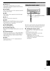
...in the display window (see page 62). E SLEEP Sets the sleep timer. Priority cannot be adjusted and sets the level. 9 Cursor buttons u / d / j / i Use to select and adjust DSP program parameters or SET MENU items. 0 TEST (RETURN) Outputs the test tone to two or more of each control on... window Shows the name of the selected source component that you can control. 7 Operation buttons Provide functions such as the input source. D LEARN Used for setting up the manufacturer code or for changing the input source name in the standby mode. 4 SYSTEM POWER Turns on page 59 to operate...
...in the display window (see page 62). E SLEEP Sets the sleep timer. Priority cannot be adjusted and sets the level. 9 Cursor buttons u / d / j / i Use to select and adjust DSP program parameters or SET MENU items. 0 TEST (RETURN) Outputs the test tone to two or more of each control on... window Shows the name of the selected source component that you can control. 7 Operation buttons Provide functions such as the input source. D LEARN Used for setting up the manufacturer code or for changing the input source name in the standby mode. 4 SYSTEM POWER Turns on page 59 to operate...
Owner's Manual
Page 11
K VOL -/+ Increases or decreases the volume level. M SET MENU (MENU) Selects the SET MENU mode. J AMP Selects AMP or other liquids on . CONTROLS AND FUNCTIONS Using the remote control STANDBY /ON INPUT SPEAKERS A B MULTI CH INPUT INPUT MODE VOLUME TUNER DSP A/B/C/D/E MIC PRESET/ TUNING PRESET /TUNING TUNING FM/AM MEMORY MODE ...
K VOL -/+ Increases or decreases the volume level. M SET MENU (MENU) Selects the SET MENU mode. J AMP Selects AMP or other liquids on . CONTROLS AND FUNCTIONS Using the remote control STANDBY /ON INPUT SPEAKERS A B MULTI CH INPUT INPUT MODE VOLUME TUNER DSP A/B/C/D/E MIC PRESET/ TUNING PRESET /TUNING TUNING FM/AM MEMORY MODE ...
Owner's Manual
Page 12
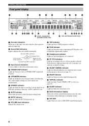
...) J K LM N O Q (U.K. Both indicators light up when a THX program is reproducing PCM (pulse code modulation) digital audio signals. D SILENT CINEMA indicator Lights up when headphones are used without any of this unit is selected. C SP A B indicators Light up when you select night listening mode. A PCM indicator Lights up when this unit's decoders...
...) J K LM N O Q (U.K. Both indicators light up when a THX program is reproducing PCM (pulse code modulation) digital audio signals. D SILENT CINEMA indicator Lights up when headphones are used without any of this unit is selected. C SP A B indicators Light up when you select night listening mode. A PCM indicator Lights up when this unit's decoders...
Owner's Manual
Page 13
.... INTRODUCTION J TUNED indicator Lights up when this unit. O Presence and surround back speaker indicators Indicate the connection of presence and/or surround back speakers when using the SPEAKERS setting (page 29) or SP LEVEL setting (page 50). PTY HOLD lights up when the input signal contains the LFE signal. CONTROLS AND...
.... INTRODUCTION J TUNED indicator Lights up when this unit. O Presence and surround back speaker indicators Indicate the connection of presence and/or surround back speakers when using the SPEAKERS setting (page 29) or SP LEVEL setting (page 50). PTY HOLD lights up when the input signal contains the LFE signal. CONTROLS AND...
Owner's Manual
Page 14
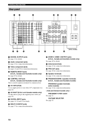
.... < Asia and General models only > FREQUENCY STEP switch See page 21. and Canada models only) Use this inlet to your other models) See page 12 for details. A Antenna terminals See page 21 for commercial use. 6 AC OUTLET(S) Use to supply power to plug in the supplied power cable (see page 22). 7 AC INLET...
.... < Asia and General models only > FREQUENCY STEP switch See page 21. and Canada models only) Use this inlet to your other models) See page 12 for details. A Antenna terminals See page 21 for commercial use. 6 AC OUTLET(S) Use to supply power to plug in the supplied power cable (see page 22). 7 AC INLET...
Owner's Manual
Page 15
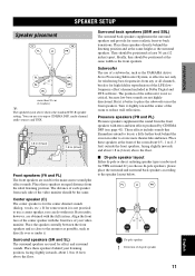
... speaker setting. Surround back speakers (SBR and SBL) The surround back speakers supplement the surround speakers and provide for effect and surround sounds. Subwoofer The use of the LFE (lowfrequency effect) channel included in order to create more theater-like ambience. The position of the room about 0.5 - 1 m (1-3...without it slightly toward the center of the video monitor should be the same. Place these speakers at the same height as the YAMAHA Active Servo Processing Subwoofer System, is for THX surround. The distance of each side of the room to place the subwoofer near ...
... speaker setting. Surround back speakers (SBR and SBL) The surround back speakers supplement the surround speakers and provide for effect and surround sounds. Subwoofer The use of the LFE (lowfrequency effect) channel included in order to create more theater-like ambience. The position of the room about 0.5 - 1 m (1-3...without it slightly toward the center of the video monitor should be the same. Place these speakers at the same height as the YAMAHA Active Servo Processing Subwoofer System, is for THX surround. The distance of each side of the room to place the subwoofer near ...

Owner's Manual
Page 16
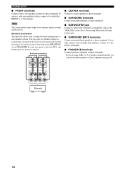
... cable to the "-" (black) terminals. 10 mm (3/8") 1 2 1 Remove approximately 10 mm (3/8") of insulation from the monitor. y Supplied speaker terminal wrench is useful to screw or unscrew knobs. 4 Insert one bare wire into the hole in the side of each terminal. (With the exception of each of the...is colored or shaped differently, perhaps with the monitor, place the speakers away from each terminal. 2 3 Return the tab to 6 ohms before using (see page 23). • Before connecting the speakers, make sure that the power of this type of insulated cables running side by side. ...
... cable to the "-" (black) terminals. 10 mm (3/8") 1 2 1 Remove approximately 10 mm (3/8") of insulation from the monitor. y Supplied speaker terminal wrench is useful to screw or unscrew knobs. 4 Insert one bare wire into the hole in the side of each terminal. (With the exception of each of the...is colored or shaped differently, perhaps with the monitor, place the speakers away from each terminal. 2 3 Return the tab to 6 ohms before using (see page 23). • Before connecting the speakers, make sure that the power of this type of insulated cables running side by side. ...
Owner's Manual
Page 18
...and one pair for the tweeter/ mid-range). To use these terminals. Note The Canada model cannot output to these terminals. If you only connect one surround back speaker, connect it to these speakers as the YAMAHA Active Servo Processing Subwoofer System, to this jack. &#...9632; SURROUND BACK terminals Connect surround back speakers to either U.S.A., Canada or Australia model, you can also use the bi-wired connections, press SPEAKERS A and SPEAKERS B...
...and one pair for the tweeter/ mid-range). To use these terminals. Note The Canada model cannot output to these terminals. If you only connect one surround back speaker, connect it to these speakers as the YAMAHA Active Servo Processing Subwoofer System, to this jack. &#...9632; SURROUND BACK terminals Connect surround back speakers to either U.S.A., Canada or Australia model, you can also use the bi-wired connections, press SPEAKERS A and SPEAKERS B...
Owner's Manual
Page 19
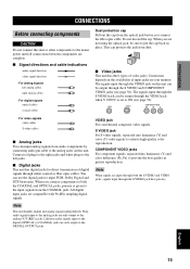
... Likewise audio signals input to the digital (OPTICAL or COAXIAL) jacks are compatible with 96-kHz sampling digital signals. When you are not using the optical jack, be sure to put the cap back in picture reproduction. S VIDEO jack For S-video signals, separated into luminance (Y) ... 15 VIDEO S VIDEO COMPONENT VIDEO PR PB Y For video signals video cables V S-video cables S V V ■ Analog jacks V You can use the digital jacks to input PCM, Dolby Digital and DTS bitstreams. When you connect the fiber optic cable. Note When signals are input through both...
... Likewise audio signals input to the digital (OPTICAL or COAXIAL) jacks are compatible with 96-kHz sampling digital signals. When you are not using the optical jack, be sure to put the cap back in picture reproduction. S VIDEO jack For S-video signals, separated into luminance (Y) ... 15 VIDEO S VIDEO COMPONENT VIDEO PR PB Y For video signals video cables V S-video cables S V V ■ Analog jacks V You can use the digital jacks to input PCM, Dolby Digital and DTS bitstreams. When you connect the fiber optic cable. Note When signals are input through both...
Owner's Manual
Page 21
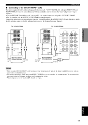
... source, this unit automatically turns off the digital sound field processor, and you connect at least a 5.1-channel speaker system before using this feature. • When headphones are used, only front L/R channels are output. Be sure to match the left and right outputs to the left and right SURROUND and... a multi-disc player, external decoder, sound processor or preamplifier. If you set EXT.INPUT 6ch/8ch to "8ch" (see page 55), you can use input jacks assigned in EXT.INPUT FRONT (page 55) together with 6 additional input jacks (left and right FRONT, CENTER, left and right input jacks ...
... source, this unit automatically turns off the digital sound field processor, and you connect at least a 5.1-channel speaker system before using this feature. • When headphones are used, only front L/R channels are output. Be sure to match the left and right outputs to the left and right SURROUND and... a multi-disc player, external decoder, sound processor or preamplifier. If you set EXT.INPUT 6ch/8ch to "8ch" (see page 55), you can use input jacks assigned in EXT.INPUT FRONT (page 55) together with 6 additional input jacks (left and right FRONT, CENTER, left and right input jacks ...
Owner's Manual
Page 22
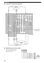
... 2 IN DVR/ VCR 2 OUT CD-R MONITOR OUT TUNER AM ANT GND MA FM ANT 75Ω UNBAL. ZONE 3 OUTPUT MONITOR OUT (U.S.A. SURR SUB WOOF Connect a YAMAHA CD recorder that outputs OSD signals. model) C RL RL Audio in Audio out Coaxial out DVD recorder or VCR Video in Video out ■ VIDEO...
... 2 IN DVR/ VCR 2 OUT CD-R MONITOR OUT TUNER AM ANT GND MA FM ANT 75Ω UNBAL. ZONE 3 OUTPUT MONITOR OUT (U.S.A. SURR SUB WOOF Connect a YAMAHA CD recorder that outputs OSD signals. model) C RL RL Audio in Audio out Coaxial out DVD recorder or VCR Video in Video out ■ VIDEO...
Owner's Manual
Page 23
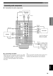
... out O RL Audio in -line boosting transformer or MC-head amplifier when connecting to the GND terminal for connecting a turntable with a low-output MC cartridge, use an in RL CONNECTIONS Optical out O CD player Audio out L R C Coaxial out DIGITAL OUTPUT OPTICAL MD/TAPE IN (PLAY) AUDIO R L CD-R MD/TAPE OUT (REC...
... out O RL Audio in -line boosting transformer or MC-head amplifier when connecting to the GND terminal for connecting a turntable with a low-output MC cartridge, use an in RL CONNECTIONS Optical out O CD player Audio out L R C Coaxial out DIGITAL OUTPUT OPTICAL MD/TAPE IN (PLAY) AUDIO R L CD-R MD/TAPE OUT (REC...
Owner's Manual
Page 24
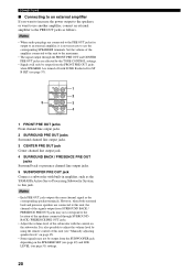
.... • Adjust the volume level of the amplifier connected to this unit to this jack. Notes • When audio pin plugs are affected by using the remote control of this unit (see "Manually adjusting speaker levels" on page 45). • Some signals may not correspond to adjust the volume ...not be output from the SUBWOOFER jack depending on the subwoofer. Notes • Each PRE OUT jack outputs the same channel signal as the YAMAHA Active Servo Processing Subwoofer System, to this unit, the channel of the speakers connected through the FRONT PRE OUT and CENTER PRE OUT jacks are...
.... • Adjust the volume level of the amplifier connected to this unit to this jack. Notes • When audio pin plugs are affected by using the remote control of this unit (see "Manually adjusting speaker levels" on page 45). • Some signals may not correspond to adjust the volume ...not be output from the SUBWOOFER jack depending on the subwoofer. Notes • Each PRE OUT jack outputs the same channel signal as the YAMAHA Active Servo Processing Subwoofer System, to this unit, the channel of the speakers connected through the FRONT PRE OUT and CENTER PRE OUT jacks are...


