

Owner's Manual
Page 2
.../uses radio frequencies and, if not installed and used . If this product in a residential environment will not occur in FCC Regulations, Part 15 for replacement of Graphical Symbols The lightning flash with the manufacturer's instructions. 8 Do not install near water. 6 Clean only... used according to the instructions found to be the source of interference, which can not locate the appropriate retailer, please contact Yamaha Corporation of important operating and maintenance (servicing) instructions in this type of electric shock to eliminate the problem by the interference....
.../uses radio frequencies and, if not installed and used . If this product in a residential environment will not occur in FCC Regulations, Part 15 for replacement of Graphical Symbols The lightning flash with the manufacturer's instructions. 8 Do not install near water. 6 Clean only... used according to the instructions found to be the source of interference, which can not locate the appropriate retailer, please contact Yamaha Corporation of important operating and maintenance (servicing) instructions in this type of electric shock to eliminate the problem by the interference....
Owner's Manual
Page 4
... electric plug from the device or an outlet, always hold the plug itself and not the cord. The device contains no user-serviceable parts. CAUTION Always follow the basic precautions listed below to avoid the possibility of serious injury or even death from electrical shock, short-circuiting,...or damaged, immediately turn off the power switch, disconnect the electric plug from the outlet, and have the device inspected by qualified Yamaha service personnel. • If this manual in a safe place for future reference. WARNING Always follow the basic precautions listed below to be...
... electric plug from the device or an outlet, always hold the plug itself and not the cord. The device contains no user-serviceable parts. CAUTION Always follow the basic precautions listed below to avoid the possibility of serious injury or even death from electrical shock, short-circuiting,...or damaged, immediately turn off the power switch, disconnect the electric plug from the outlet, and have the device inspected by qualified Yamaha service personnel. • If this manual in a safe place for future reference. WARNING Always follow the basic precautions listed below to be...
Owner's Manual
Page 8
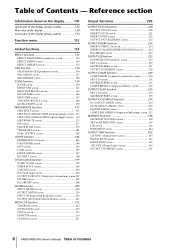
Table of Contents Reference section Information shown in the display.......... 149 Upper part of the display (always visible 149 Main area of the display 150 Lower part of the display (always visible 150 Function menu 151 Global functions 152 EFFECT functions 152 EFFECT PARAM (Effect parameter) screen 152 EFFECT ASSIGN screen 154 ... CH VIEW (Channel view) screen 245 SIGNAL FLOW screen 247 FADER VIEW screen 249 CH COPY (Channel copy) screen 249 OUTPUT CH LIBRARY screen 251 8 PM5D/PM5D-RH Owner's Manual Table of Contents -
Table of Contents Reference section Information shown in the display.......... 149 Upper part of the display (always visible 149 Main area of the display 150 Lower part of the display (always visible 150 Function menu 151 Global functions 152 EFFECT functions 152 EFFECT PARAM (Effect parameter) screen 152 EFFECT ASSIGN screen 154 ... CH VIEW (Channel view) screen 245 SIGNAL FLOW screen 247 FADER VIEW screen 249 CH COPY (Channel copy) screen 249 OUTPUT CH LIBRARY screen 251 8 PM5D/PM5D-RH Owner's Manual Table of Contents -
Owner's Manual
Page 14
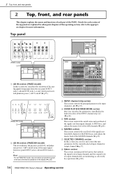
...(➥ p.57). D FADER FLIP/ENCODER MODE section Here you can select the parameters controlled by key operations (➥ p.100). 14 PM5D/PM5D-RH Owner's Manual Operating section G SELECTED CHANNEL section In this section you can adjust the sensitivity of the ana- 3 log signals being... the master level of the MATRIX channels (➥ p.55). Top panel (PM5D model) 1 6 4 5 8 7 A AD IN section (PM5D model) In this section you can view and control the mix parameters for each part of the top panel are controlled by operations in subsequent chapters of this operating...
...(➥ p.57). D FADER FLIP/ENCODER MODE section Here you can select the parameters controlled by key operations (➥ p.100). 14 PM5D/PM5D-RH Owner's Manual Operating section G SELECTED CHANNEL section In this section you can adjust the sensitivity of the ana- 3 log signals being... the master level of the MATRIX channels (➥ p.55). Top panel (PM5D model) 1 6 4 5 8 7 A AD IN section (PM5D model) In this section you can view and control the mix parameters for each part of the top panel are controlled by operations in subsequent chapters of this operating...
Owner's Manual
Page 15
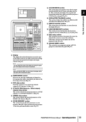
...1-4 or FX RTN channels 1-4 (➥ p.39). R USER DEFINED KEYS sections This section executes the functions that is fastened in place. Note Before moving the upper part of channels or DCA groups that will be used when you must lower the display all the way back until it is output from the... panel (➥ p.73). PM5D/PM5D-RH Owner's Manual Operating section 15 Hint You can select the combination of the display frame forward or backward. L ST IN/FX RTN (Stereo in...
...1-4 or FX RTN channels 1-4 (➥ p.39). R USER DEFINED KEYS sections This section executes the functions that is fastened in place. Note Before moving the upper part of channels or DCA groups that will be used when you must lower the display all the way back until it is output from the... panel (➥ p.73). PM5D/PM5D-RH Owner's Manual Operating section 15 Hint You can select the combination of the display frame forward or backward. L ST IN/FX RTN (Stereo in...
Owner's Manual
Page 32
... section The input signals from the rear panel WORD CLOCK IN connector. The PM5D will follow the word clock signal being input or the clock cannot be detected. 2 In the MASTER CLOCK SELECT area located in the upper part of the screen, click a button to the CASCADE IN connector. To initialize the.... (However, the word clock master selection is turned on /off the power. 4 Connections and setup Use the MASTER CLOCK SELECT area located in the upper part of the screen to make this setting again. You can then be enabled. As long as the MY8-AE96S) that when scene number "000" is...
... section The input signals from the rear panel WORD CLOCK IN connector. The PM5D will follow the word clock signal being input or the clock cannot be detected. 2 In the MASTER CLOCK SELECT area located in the upper part of the screen, click a button to the CASCADE IN connector. To initialize the.... (However, the word clock master selection is turned on /off the power. 4 Connections and setup Use the MASTER CLOCK SELECT area located in the upper part of the screen to make this setting again. You can then be enabled. As long as the MY8-AE96S) that when scene number "000" is...
Owner's Manual
Page 71
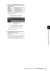
... a slot to turn on . This enables the insert connection for the channel at which an external head amp supporting the special protocol (Yamaha AD8HR, AD824) is connected, make head amp settings as the insert I/O point for the desired channel to which the cursor is indicated by... or if you selected AD IN as the insert-in the upper part of the input channels. 8 These indicate the channel numbers. 6 Click the INSERT I /O point for the corresponding channel. Input Patch / Output Patch operations PM5D/PM5D-RH Owner's Manual Operating section 71 PRE EQ POST EQ PRE DELAY...
... a slot to turn on . This enables the insert connection for the channel at which an external head amp supporting the special protocol (Yamaha AD8HR, AD824) is connected, make head amp settings as the insert I/O point for the desired channel to which the cursor is indicated by... or if you selected AD IN as the insert-in the upper part of the input channels. 8 These indicate the channel numbers. 6 Click the INSERT I /O point for the corresponding channel. Input Patch / Output Patch operations PM5D/PM5D-RH Owner's Manual Operating section 71 PRE EQ POST EQ PRE DELAY...
Owner's Manual
Page 72
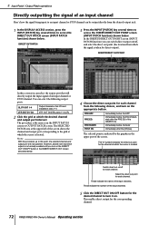
... select the output port that direct output is indicated by the graphic in the upper part of the screen. The procedure is taken for each channel. Select the direct out point for the corresponding channel. 72 PM5D/PM5D-RH Owner's Manual Operating section You can be output directly from the desired output jack...
... select the output port that direct output is indicated by the graphic in the upper part of the screen. The procedure is taken for each channel. Select the direct out point for the corresponding channel. 72 PM5D/PM5D-RH Owner's Manual Operating section You can be output directly from the desired output jack...
Owner's Manual
Page 74
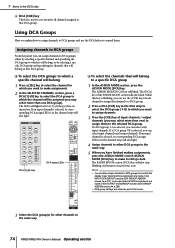
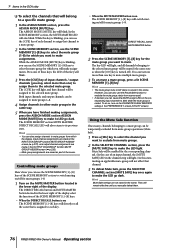
.... The [DCA] key of the FADER MODE section will blink. DCA [1]-[8] keys DCA assign LEDs ❏ To select the channels that are saved as part of the scene. 3 Select the DCA group(s) for other DCA groups in the same way. 5 When you have finished making assignments, press the ASSIGN ... light for which the channel will be assigned (you can use the DCA faders to control them to other channels in the same way. 74 PM5D/PM5D-RH Owner's Manual Operating section While this key is selected, its corresponding DCA assign LED(s) in the channel strip will also light. 4 Assign channels...
.... The [DCA] key of the FADER MODE section will blink. DCA [1]-[8] keys DCA assign LEDs ❏ To select the channels that are saved as part of the scene. 3 Select the DCA group(s) for other DCA groups in the same way. 5 When you have finished making assignments, press the ASSIGN ... light for which the channel will be assigned (you can use the DCA faders to control them to other channels in the same way. 74 PM5D/PM5D-RH Owner's Manual Operating section While this key is selected, its corresponding DCA assign LED(s) in the channel strip will also light. 4 Assign channels...
Owner's Manual
Page 76
... MEMORY section, the MUTE MASTER LED will belong to select the mute group (1-8) for which you may select more than one) to assign them . 76 PM5D/PM5D-RH Owner's Manual Operating section Hint • You can also use the SCENE MEMORY [1]-[8] keys to a specific mute group 1 In the ASSIGN MODE section... key to make the LED go dark. Hint • The mute group mute on The SCENE MEMORY [1]-[8] keys will be muted (the same state as part of an input channel, the [MUTE SAFE] LED in the scene. However, you want to blink while the mute group is on /off for the...
... MEMORY section, the MUTE MASTER LED will belong to select the mute group (1-8) for which you may select more than one) to assign them . 76 PM5D/PM5D-RH Owner's Manual Operating section Hint • You can also use the SCENE MEMORY [1]-[8] keys to a specific mute group 1 In the ASSIGN MODE section... key to make the LED go dark. Hint • The mute group mute on The SCENE MEMORY [1]-[8] keys will be muted (the same state as part of an input channel, the [MUTE SAFE] LED in the scene. However, you want to blink while the mute group is on /off for the...
Owner's Manual
Page 78
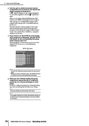
... group in the DCA strip 2 Click the grid at the corresponding grid. Note The STEREO LINK button and KEY IN SOURCE settings are saved as part of a channel belonging to a link group. In the case of output channel EQ link groups, MIX channels and STEREO A/B channels can be assigned only to... in the screen to turn it to a link group, click the SET BY CUE button for channels belonging to the same compressor link group. 78 PM5D/PM5D-RH Owner's Manual Operating section The EQ or compressor parameters of each channel to assign it on will be defeated. 4 When you have finished making...
... group in the DCA strip 2 Click the grid at the corresponding grid. Note The STEREO LINK button and KEY IN SOURCE settings are saved as part of a channel belonging to a link group. In the case of output channel EQ link groups, MIX channels and STEREO A/B channels can be assigned only to... in the screen to turn it to a link group, click the SET BY CUE button for channels belonging to the same compressor link group. 78 PM5D/PM5D-RH Owner's Manual Operating section The EQ or compressor parameters of each channel to assign it on will be defeated. 4 When you have finished making...
Owner's Manual
Page 81
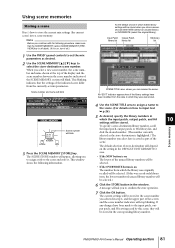
...LIBRARY NO. area. • If the NEW button is on The lowest of the indicated scene differ from the currently-set the mix parameters as part of store-destination will be stored. Using scene memories Storing a scene Here's how to confirm the store operation. 7 Click the OK button. ...Scene number and name will blink Scene number will be stored in the window. Scene memory 10 PM5D/PM5D-RH Owner's Manual Operating section 81 Note Before you to store the current mix settings (the current scene) into a scene memory. A message will...
...LIBRARY NO. area. • If the NEW button is on The lowest of the indicated scene differ from the currently-set the mix parameters as part of store-destination will be stored. Using scene memories Storing a scene Here's how to confirm the store operation. 7 Click the OK button. ...Scene number and name will blink Scene number will be stored in the window. Scene memory 10 PM5D/PM5D-RH Owner's Manual Operating section 81 Note Before you to store the current mix settings (the current scene) into a scene memory. A message will...
Owner's Manual
Page 85
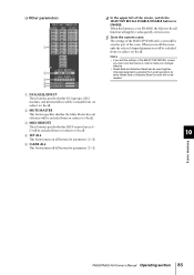
.... Channels/parameters excluded from recall operations by either Recall Safe or Selective Recall (or both) will be saved as part of the SELECTIVE RECALL screen will not be recalled. 10 Scene memory PM5D/PM5D-RH Owner's Manual Operating section 85 ❏ Other parameters 1 2 3 4 5 A DCA/GEQ/EFFECT These buttons specify whether DCA groups, GEQ...
.... Channels/parameters excluded from recall operations by either Recall Safe or Selective Recall (or both) will be saved as part of the SELECTIVE RECALL screen will not be recalled. 10 Scene memory PM5D/PM5D-RH Owner's Manual Operating section 85 ❏ Other parameters 1 2 3 4 5 A DCA/GEQ/EFFECT These buttons specify whether DCA groups, GEQ...
Owner's Manual
Page 87
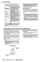
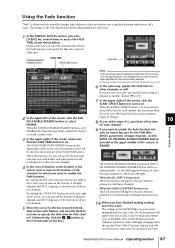
... the screen) to turn on the buttons of all input channels and all DCA groups, or the buttons of all output channels. Scene memory 10 PM5D/PM5D-RH Owner's Manual Operating section 87 Using the Fade function "Fade" is on. If desired, you recall a scene for the PAN (BALANCE) parameters of all.../DISABLE button and INPUT CH PANNING ENABLE/DISABLE button can turn it on The Fade function will be enabled for the faders in the lower part of the screen, click the FADING ENABLE/DISABLE button to ENABLE, the Fade function will reach their new values over the specified Fade Time. Use...
... the screen) to turn on the buttons of all input channels and all DCA groups, or the buttons of all output channels. Scene memory 10 PM5D/PM5D-RH Owner's Manual Operating section 87 Using the Fade function "Fade" is on. If desired, you recall a scene for the PAN (BALANCE) parameters of all.../DISABLE button and INPUT CH PANNING ENABLE/DISABLE button can turn it on The Fade function will be enabled for the faders in the lower part of the screen, click the FADING ENABLE/DISABLE button to ENABLE, the Fade function will reach their new values over the specified Fade Time. Use...
Owner's Manual
Page 106
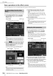
For details on the type of scene memory. 106 PM5D/PM5D-RH Owner's Manual Operating section Hint You can also be selected in this screen...at the end of the box in the effect library. The selected library item will be stored in the lower part of the list. Note You cannot change the effect type, you chose. EFFECT PARAM LIBRARY button The effect ... you click a library item in the EFFECT PARAM screen. 14 Effects Basic operations in the scene. The lower part of the screen will depend on the effect parameters, refer to the Appendices at the right of the screen, ...
For details on the type of scene memory. 106 PM5D/PM5D-RH Owner's Manual Operating section Hint You can also be selected in this screen...at the end of the box in the effect library. The selected library item will be stored in the lower part of the list. Note You cannot change the effect type, you chose. EFFECT PARAM LIBRARY button The effect ... you click a library item in the EFFECT PARAM screen. 14 Effects Basic operations in the scene. The lower part of the screen will depend on the effect parameters, refer to the Appendices at the right of the screen, ...
Owner's Manual
Page 111
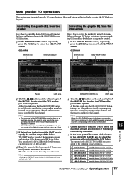
... the graphic EQ using the keys and faders of the MODULE box to select the GEQ module you want to operate. Hint • The upper part of the faders. If a signal is being input to the corresponding channel, the level of each fader is inserted will reset all faders to specify... E 2.00k-10.0k button The eight bands 2.00 kHz-10.0 kHz F 4.00k-20.0k button The eight bands 4.00 kHz-20.0 kHz Graphic EQ 15 PM5D/PM5D-RH Owner's Manual Operating section 111 Also make sure that the GEQ ON/OFF button is enabled for control. 1 In the DISPLAY ACCESS section, repeatedly...
... the graphic EQ using the keys and faders of the MODULE box to select the GEQ module you want to operate. Hint • The upper part of the faders. If a signal is being input to the corresponding channel, the level of each fader is inserted will reset all faders to specify... E 2.00k-10.0k button The eight bands 2.00 kHz-10.0 kHz F 4.00k-20.0k button The eight bands 4.00 kHz-20.0 kHz Graphic EQ 15 PM5D/PM5D-RH Owner's Manual Operating section 111 Also make sure that the GEQ ON/OFF button is enabled for control. 1 In the DISPLAY ACCESS section, repeatedly...

Owner's Manual
Page 112
... if you turn on , you can hold down the [SHIFT] key and press a FADER MODE [A]-[F] key. The faders of the selected region are saved as part of that frequency region. While the DCA [MUTE] key is lit, pressing the DCA [MUTE] key will light. The settings of a GEQ module is at... EQ When a button is clicked, you can use the DCA faders to control a different region, repeat steps 4-5. 7 When you access the GEQ PARAM screen. 112 PM5D/PM5D-RH Owner's Manual Operating section Hint If the fader of a GEQ module can also be boosted or cut.
... if you turn on , you can hold down the [SHIFT] key and press a FADER MODE [A]-[F] key. The faders of the selected region are saved as part of that frequency region. While the DCA [MUTE] key is lit, pressing the DCA [MUTE] key will light. The settings of a GEQ module is at... EQ When a button is clicked, you can use the DCA faders to control a different region, repeat steps 4-5. 7 When you access the GEQ PARAM screen. 112 PM5D/PM5D-RH Owner's Manual Operating section Hint If the fader of a GEQ module can also be boosted or cut.
Owner's Manual
Page 118
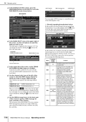
...Use the channel select area at right. 7 Use the MIDI message boxes in any of the screen to assign a MIDI message. The lower part of the encoder is transmitted when the key is transmitted (hexadecimal). Value Available assignments Content 00(H)- sage. ENC ENCODER ON/ ENCODER Indicates the ...to an encoder, a value of the encoder [ON] key or the channel [ON] key. ted when the key turns on . 118 PM5D/PM5D-RH Owner's Manual Operating section If assigned to the following values. All sponding controller, the MIDI message from the beginning until immediately before END ...
...Use the channel select area at right. 7 Use the MIDI message boxes in any of the screen to assign a MIDI message. The lower part of the encoder is transmitted when the key is transmitted (hexadecimal). Value Available assignments Content 00(H)- sage. ENC ENCODER ON/ ENCODER Indicates the ...to an encoder, a value of the encoder [ON] key or the channel [ON] key. ted when the key turns on . 118 PM5D/PM5D-RH Owner's Manual Operating section If assigned to the following values. All sponding controller, the MIDI message from the beginning until immediately before END ...
Owner's Manual
Page 119
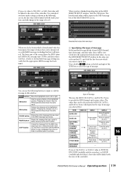
... the same result. Pressure value (0-127) PITCH BEND Pitch bend Pitch bend LSB MSB (0-127) (0-127) EXCLUSIVE MESSAGE - Remote control 16 PM5D/PM5D-RH Owner's Manual Operating section 119 Hexadecimal values that were input B Specifying the type of message In this in conjunction with the fader position,... if you have finished inputting data in this MIDI message, letting you verify that the appropriate MIDI message has been input. The lower part of a PS/2 keyboard will produce the same result. Pressing the key of the screen shows the MIDI channel (MIDI CH), message ...
... the same result. Pressure value (0-127) PITCH BEND Pitch bend Pitch bend LSB MSB (0-127) (0-127) EXCLUSIVE MESSAGE - Remote control 16 PM5D/PM5D-RH Owner's Manual Operating section 119 Hexadecimal values that were input B Specifying the type of message In this in conjunction with the fader position,... if you have finished inputting data in this MIDI message, letting you verify that the appropriate MIDI message has been input. The lower part of a PS/2 keyboard will produce the same result. Pressing the key of the screen shows the MIDI channel (MIDI CH), message ...
Owner's Manual
Page 121
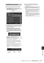
...the corresponding channel strip will function as MIDI remote channels. (The usual function of the controllers will be disabled.) At this time, the lower part of the display will be enabled. • The controller values during MIDI Remote operation are allowed.) INPUT CH STIN/FXRTN INPUT channel strip 1-24...RTN channel strip 1-4 This setting applies to all four banks. Encoder/fader mode area INPUT CH layer ST IN/FX RTN layer 16 Remote control PM5D/PM5D-RH Owner's Manual Operating section 121 Using MIDI remote channels Here's how to recall banks A-D to which you want to use. 3 In ...
...the corresponding channel strip will function as MIDI remote channels. (The usual function of the controllers will be disabled.) At this time, the lower part of the display will be enabled. • The controller values during MIDI Remote operation are allowed.) INPUT CH STIN/FXRTN INPUT channel strip 1-24...RTN channel strip 1-4 This setting applies to all four banks. Encoder/fader mode area INPUT CH layer ST IN/FX RTN layer 16 Remote control PM5D/PM5D-RH Owner's Manual Operating section 121 Using MIDI remote channels Here's how to recall banks A-D to which you want to use. 3 In ...


