
Owner's Manual
Page 8
... USER DEFINE screen 189 SAVE screen 192 LOAD screen 195 FADER ASSIGN screen 197 SECURITY screen 198 SYS/W.CLOCK function 199 WORD CLOCK screen 199 MIXER SETUP screen 200 CASCADE screen 204 HA (Head Amp) screen 206 OUTPUT PORT ATT (Output port attenuation) screen 207 DITHER screen 207 HA LIBRARY screen... CH VIEW (Channel view) screen 245 SIGNAL FLOW screen 247 FADER VIEW screen 249 CH COPY (Channel copy) screen 249 OUTPUT CH LIBRARY screen 251 8 PM5D/PM5D-RH Owner's Manual Table of Contents -
... USER DEFINE screen 189 SAVE screen 192 LOAD screen 195 FADER ASSIGN screen 197 SECURITY screen 198 SYS/W.CLOCK function 199 WORD CLOCK screen 199 MIXER SETUP screen 200 CASCADE screen 204 HA (Head Amp) screen 206 OUTPUT PORT ATT (Output port attenuation) screen 207 DITHER screen 207 HA LIBRARY screen... CH VIEW (Channel view) screen 245 SIGNAL FLOW screen 247 FADER VIEW screen 249 CH COPY (Channel copy) screen 249 OUTPUT CH LIBRARY screen 251 8 PM5D/PM5D-RH Owner's Manual Table of Contents -
Owner's Manual
Page 10
...10063; Surround panning Surround pan functionality allows multi-channel playback systems to be controlled by the eight DCA faders on an analog mixer. Effects such as extended signal processors via internal buses or inserted into the desired channel. 31-band graphic EQ can also be... provide additional effect types Separately sold as up to 500 scenes for purchasing the Yamaha PM5D digital mixing console. Effects, input/output patching, input channel/output channel settings, internal head amp (PM5D-RH model only) or external head amp settings can be linked. In particular when...
...10063; Surround panning Surround pan functionality allows multi-channel playback systems to be controlled by the eight DCA faders on an analog mixer. Effects such as extended signal processors via internal buses or inserted into the desired channel. 31-band graphic EQ can also be... provide additional effect types Separately sold as up to 500 scenes for purchasing the Yamaha PM5D digital mixing console. Effects, input/output patching, input channel/output channel settings, internal head amp (PM5D-RH model only) or external head amp settings can be linked. In particular when...
Owner's Manual
Page 45
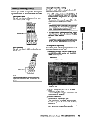
... enable or disable pairing for channels of different layers that are two types of the other channel. PM5D/PM5D-RH Owner's Manual Operating section 45 For example if you press the [SEL] keys. MIXER SETUP VERTICAL PAIR button Vertical pair Hint Input channels that share the same fader. 1 Repeatedly press ... pairing, hold down the [SEL] key of one of the paired channels and press the [SEL] key of the DISPLAY ACCESS section until the MIXER SETUP screen appears. When you can use "vertical pair" mode. you switch to "vertical pair" mode, new numbers will have their principal parameters....
... enable or disable pairing for channels of different layers that are two types of the other channel. PM5D/PM5D-RH Owner's Manual Operating section 45 For example if you press the [SEL] keys. MIXER SETUP VERTICAL PAIR button Vertical pair Hint Input channels that share the same fader. 1 Repeatedly press ... pairing, hold down the [SEL] key of one of the paired channels and press the [SEL] key of the DISPLAY ACCESS section until the MIXER SETUP screen appears. When you can use "vertical pair" mode. you switch to "vertical pair" mode, new numbers will have their principal parameters....
Owner's Manual
Page 57
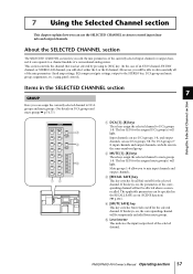
...The SELECTED CHANNEL section lets you can be able to edit essentially all of the currently selected input channel or output channel; PM5D/PM5D-RH Owner's Manual Operating section 57 it corresponds to a channel module of the selected channel. This section controls the channel ... DCA [1]-[8] keys These keys assign the selected channel to DCA groups 1-8. E Level meter This indicates the input/output level of a conventional analog mixer. 7 Using the Selected Channel section This chapter explains how you to mix input channels and output channels. Input channels can use DCA groups 1-8, ...
...The SELECTED CHANNEL section lets you can be able to edit essentially all of the currently selected input channel or output channel; PM5D/PM5D-RH Owner's Manual Operating section 57 it corresponds to a channel module of the selected channel. This section controls the channel ... DCA [1]-[8] keys These keys assign the selected channel to DCA groups 1-8. E Level meter This indicates the input/output level of a conventional analog mixer. 7 Using the Selected Channel section This chapter explains how you to mix input channels and output channels. Input channels can use DCA groups 1-8, ...
Owner's Manual
Page 79
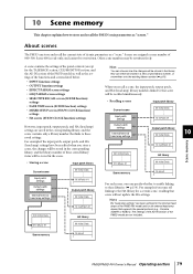
... off linking to these saved settings. Scene memory 10 HA #1 Scene memory 10 PM5D/PM5D-RH Owner's Manual Operating section 79 A scene contains the settings of the panel ... SELECTIVE RECALL screen (SCENE function) settings • FADE TIME screen (SCENE function) settings • MIXER SETUP screen (SYS/W.CLOCK function) settings • HA screen (SYS/W.CLOCK function) settings However, input... patch, and HA (head amp) library numbers linked to that supports the special protocol (e.g., Yamaha AD8HR or AD824). they can store and recall the current state of these stored library items...
... off linking to these saved settings. Scene memory 10 HA #1 Scene memory 10 PM5D/PM5D-RH Owner's Manual Operating section 79 A scene contains the settings of the panel ... SELECTIVE RECALL screen (SCENE function) settings • FADE TIME screen (SCENE function) settings • MIXER SETUP screen (SYS/W.CLOCK function) settings • HA screen (SYS/W.CLOCK function) settings However, input... patch, and HA (head amp) library numbers linked to that supports the special protocol (e.g., Yamaha AD8HR or AD824). they can store and recall the current state of these stored library items...
Owner's Manual
Page 93
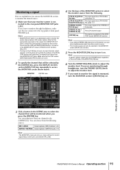
... input channel, output channel, or DCA group will override the settings of the MONITOR section and cause the Cue signal to be selected in the MIXER SETUP screen (SYS/W.CLOCK function) (➥ p.201). • Turning on . MONITOR DEFINE area 4 Use the keys of the MONITOR [ON] key. 6 Turn the ...source. • The monitor source can also be output from the following . [2TR IN A1]/[2TR IN The input signal from 2TR IN ANA- PM5D/PM5D-RH Owner's Manual Operating section 93 Monitoring a signal Here we explain how you can use the MONITOR section to monitor the desired source. 1 Make ...
... input channel, output channel, or DCA group will override the settings of the MONITOR section and cause the Cue signal to be selected in the MIXER SETUP screen (SYS/W.CLOCK function) (➥ p.201). • Turning on . MONITOR DEFINE area 4 Use the keys of the MONITOR [ON] key. 6 Turn the ...source. • The monitor source can also be output from the following . [2TR IN A1]/[2TR IN The input signal from 2TR IN ANA- PM5D/PM5D-RH Owner's Manual Operating section 93 Monitoring a signal Here we explain how you can use the MONITOR section to monitor the desired source. 1 Make ...
Owner's Manual
Page 132
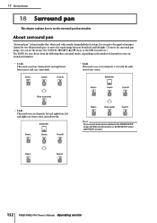
...dimensional space or move the sound image between front/back and left and right rear, front center, and subwoofer. Rear L Rear R 132 PM5D/PM5D-RH Owner's Manual Operating section left and right front, left /right. (To move the surround pan image, you choose from the following ...mode can use the surround pan functionality. About surround pan "Surround pan" is functionality that, when used with the addition of channels in the MIXER SETUP screen (SYS/W.CLOCK function) or SURR SETUP screen (MATRIX/ST function). Front L Center Front R Subwoofer Rear (surround) • 5.1ch...
...dimensional space or move the sound image between front/back and left and right rear, front center, and subwoofer. Rear L Rear R 132 PM5D/PM5D-RH Owner's Manual Operating section left and right front, left /right. (To move the surround pan image, you choose from the following ...mode can use the surround pan functionality. About surround pan "Surround pan" is functionality that, when used with the addition of channels in the MIXER SETUP screen (SYS/W.CLOCK function) or SURR SETUP screen (MATRIX/ST function). Front L Center Front R Subwoofer Rear (surround) • 5.1ch...
Owner's Manual
Page 142
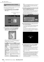
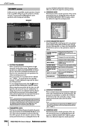
... on the items you click a button, a check mark will need to lock, click either the PARAMETER LOCK button or one of the MIXER SETUP screen and CASCADE screen Changes to the word clock setting Changes to dither-related settings Changes to the input patch settings (and names) ...Changes to lose the system password. 142 PM5D/PM5D-RH Owner's Manual Operating section If a password has been specified, a window will be unable to access the SECURITY screen. Please be disabled ...
... on the items you click a button, a check mark will need to lock, click either the PARAMETER LOCK button or one of the MIXER SETUP screen and CASCADE screen Changes to the word clock setting Changes to dither-related settings Changes to the input patch settings (and names) ...Changes to lose the system password. 142 PM5D/PM5D-RH Owner's Manual Operating section If a password has been specified, a window will be unable to access the SECURITY screen. Please be disabled ...
Owner's Manual
Page 143
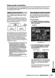
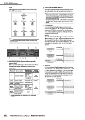
...slave. (This setting is not possible to link operations. • If you want to cascade-connect a PM5D with a Yamaha DM2000 or 02R96, connect the CASCADE OUT connector of the screen, select "MASTER". CASCADE MODE area BI-DIRECTION ...button Other functions When multiple PM5D units are cascadeconnected. Using cascade connections Buses can be shared by cascade-connecting multiple PM5D units (up to four) or the PM5D with any other external mixer...
...slave. (This setting is not possible to link operations. • If you want to cascade-connect a PM5D with a Yamaha DM2000 or 02R96, connect the CASCADE OUT connector of the screen, select "MASTER". CASCADE MODE area BI-DIRECTION ...button Other functions When multiple PM5D units are cascadeconnected. Using cascade connections Buses can be shared by cascade-connecting multiple PM5D units (up to four) or the PM5D with any other external mixer...
Owner's Manual
Page 144
... 1-4 as well as the other than the above (maximum 16 bus) SLOT 4 *1. PM5D Cascade disabled another PM5D CASCADE IN, SLOT 4, SLOT 3/4, SLOT1-4 [CH1-8], SLOT 1-4 [CH9-16] CASCADE IN Not possible Possible*1 DM2000 /02R96 YAMAHA DM2000 or 02R96 CASCADE IN MIXER [30BUS] A mixer other cascade-connected device, only "CASCADE IN" can be selected for the CASCADE...
... 1-4 as well as the other than the above (maximum 16 bus) SLOT 4 *1. PM5D Cascade disabled another PM5D CASCADE IN, SLOT 4, SLOT 3/4, SLOT1-4 [CH1-8], SLOT 1-4 [CH9-16] CASCADE IN Not possible Possible*1 DM2000 /02R96 YAMAHA DM2000 or 02R96 CASCADE IN MIXER [30BUS] A mixer other cascade-connected device, only "CASCADE IN" can be selected for the CASCADE...
Owner's Manual
Page 150
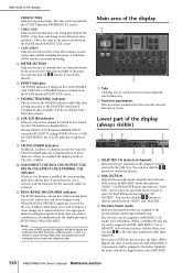
.../OSC/DIMM indicator is shown. If both the encoders and the faders, you select MIX SEND 150 PM5D/PM5D-RH Owner's Manual Reference section K BUSY/RS422/HA/GPI/MIDI indicator The BUSY indicator is shown here...received to LEVEL, MIX SEND 1-24, or REMOTE. For both are on in the SYS/W.CLOCK function MIXER SETUP screen the BUS SETUP setting STEREO B is set to select TO MATRIX mode this directly. If...are received at which LCR is BUSY>RS422>HA>GPI>MIDI. If you select LEVEL for which the PM5D system is TB>OSC>DIMM. The time can also click the / buttons to light. When RS422...
.../OSC/DIMM indicator is shown. If both the encoders and the faders, you select MIX SEND 150 PM5D/PM5D-RH Owner's Manual Reference section K BUSY/RS422/HA/GPI/MIDI indicator The BUSY indicator is shown here...received to LEVEL, MIX SEND 1-24, or REMOTE. For both are on in the SYS/W.CLOCK function MIXER SETUP screen the BUS SETUP setting STEREO B is set to select TO MATRIX mode this directly. If...are received at which LCR is BUSY>RS422>HA>GPI>MIDI. If you select LEVEL for which the PM5D system is TB>OSC>DIMM. The time can also click the / buttons to light. When RS422...
Owner's Manual
Page 183
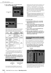
...in the screen. MY16-C Slot DME64N DME24N MY16-C Slot PM5D 2 Bi-directional connection using the CASCADE OUT connector). In the CASCADE CONNECTION area of the MIXER SETUP screen (SYS/W.CLOCK function), you will be sent from the PM5D's screen, you click the / buttons located at left ... an Ethernet cable to connect the two MY16-C cards. CASCADE CASCADE IN connector OUT connector DME64N CASCADE CASCADE IN connector OUT connector PM5D 3 Uni-directional connection using slot input/output. This function may not be displayed correctly. 1 Bi-directional connection via its CASCADE OUT...
...in the screen. MY16-C Slot DME64N DME24N MY16-C Slot PM5D 2 Bi-directional connection using the CASCADE OUT connector). In the CASCADE CONNECTION area of the MIXER SETUP screen (SYS/W.CLOCK function), you will be sent from the PM5D's screen, you click the / buttons located at left ... an Ethernet cable to connect the two MY16-C cards. CASCADE CASCADE IN connector OUT connector DME64N CASCADE CASCADE IN connector OUT connector PM5D 3 Uni-directional connection using slot input/output. This function may not be displayed correctly. 1 Bi-directional connection via its CASCADE OUT...
Owner's Manual
Page 184
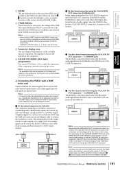
...appear. 1 2 5 34 6 The SETUP screen contains the following ports can select the PM5D port that will transmit audio signals to the DME. If necessary, click the MIXER SETUP button to access the MIXER SETUP screen (SYS/ W.CLOCK function), and change ) If this monitor signal is recalled on... can be recalled on , a program change the port you will use for cascade output. 184 PM5D/PM5D-RH Owner's Manual Reference section If necessary, click the MIXER SETUP button to access the MIXER SETUP screen (SYS/ W.CLOCK function), and change message will be transmitted to the DME via the...
...appear. 1 2 5 34 6 The SETUP screen contains the following ports can select the PM5D port that will transmit audio signals to the DME. If necessary, click the MIXER SETUP button to access the MIXER SETUP screen (SYS/ W.CLOCK function), and change ) If this monitor signal is recalled on... can be recalled on , a program change the port you will use for cascade output. 184 PM5D/PM5D-RH Owner's Manual Reference section If necessary, click the MIXER SETUP button to access the MIXER SETUP screen (SYS/ W.CLOCK function), and change message will be transmitted to the DME via the...
Owner's Manual
Page 198
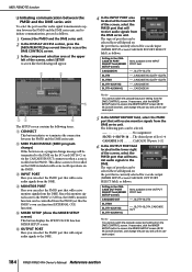
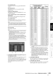
... the password, click the button to open the SYSTEM PASSWORD CHECK window, where you will need to input the console password. 198 PM5D/PM5D-RH Owner's Manual Reference section If the console password has been set . Two passwords of differing levels can be specified to lose ...temporary password (maximum of eight characters) for the first time, you will indicate "--FREE--"). SYSTEM CONFIGURATION Changes to the settings of the MIXER SETUP screen and the CASCADE screen WORD CLOCK SETUP Changes in the word clock setting DITHER Changes in the LOCK PARAMETER SELECT area (4). ...
... the password, click the button to open the SYSTEM PASSWORD CHECK window, where you will need to input the console password. 198 PM5D/PM5D-RH Owner's Manual Reference section If the console password has been set . Two passwords of differing levels can be specified to lose ...temporary password (maximum of eight characters) for the first time, you will indicate "--FREE--"). SYSTEM CONFIGURATION Changes to the settings of the MIXER SETUP screen and the CASCADE screen WORD CLOCK SETUP Changes in the word clock setting DITHER Changes in the LOCK PARAMETER SELECT area (4). ...
Owner's Manual
Page 200
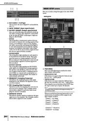
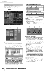
... mode, new numbers will change 200 PM5D/PM5D-RH Owner's Manual Reference section This is installed. SYS/W.CLOCK function 34 5 67 8 C Slot number / Card type This area shows the type of the INPUT channel strip to control up to 24 pairs (48 channels). MIXER SETUP screen Here you select. This ... one of the following as the method by which signals will be exchanged with a built-in sets of signals at 44.1/48 kHz is installed. MIXER SETUP 1 2 A PAIR MODE Select one of the following two methods by which input channels will be paired. • HORIZONTAL PAIR If this ...
... mode, new numbers will change 200 PM5D/PM5D-RH Owner's Manual Reference section This is installed. SYS/W.CLOCK function 34 5 67 8 C Slot number / Card type This area shows the type of the INPUT channel strip to control up to 24 pairs (48 channels). MIXER SETUP screen Here you select. This ... one of the following as the method by which signals will be exchanged with a built-in sets of signals at 44.1/48 kHz is installed. MIXER SETUP 1 2 A PAIR MODE Select one of the following two methods by which input channels will be paired. • HORIZONTAL PAIR If this ...
Owner's Manual
Page 202
...from another PM5D CASCADE IN, SLOT 3/4, SLOT 1-4 [CH1-8], SLOT 1-4 [CH9-16] CASCADE IN Not possible Possible*1 DM2000 YAMAHA DM2000 /02R96 or 02R96 CASCADE IN MIXER [30BUS] A mixer other than the above (maximum 30 bus) SLOT 3/4, SLOT 1-4 [CH1-8], SLOT 1-4 [CH9-16] Not possible MIXER [16BUS] A mixer other ... SLOT IN 2 (CH 1-16) 32 channels SLOT IN 3 (CH 1-16) SLOT IN 4 (CH 1-16) 202 PM5D/PM5D-RH Owner's Manual Reference section PM5D Cascade disabled another PM5D via input channels 1-16 of I /O card installed in the CASCADE screen. CH 1-16 SLOT 4 16 channels CASCADE IN CH...
...from another PM5D CASCADE IN, SLOT 3/4, SLOT 1-4 [CH1-8], SLOT 1-4 [CH9-16] CASCADE IN Not possible Possible*1 DM2000 YAMAHA DM2000 /02R96 or 02R96 CASCADE IN MIXER [30BUS] A mixer other than the above (maximum 30 bus) SLOT 3/4, SLOT 1-4 [CH1-8], SLOT 1-4 [CH9-16] Not possible MIXER [16BUS] A mixer other ... SLOT IN 2 (CH 1-16) 32 channels SLOT IN 3 (CH 1-16) SLOT IN 4 (CH 1-16) 202 PM5D/PM5D-RH Owner's Manual Reference section PM5D Cascade disabled another PM5D via input channels 1-16 of I /O card installed in the CASCADE screen. CH 1-16 SLOT 4 16 channels CASCADE IN CH...
Owner's Manual
Page 205
... input channel to the settings of the CASCADE IN PORT SELECT area of the MIXER SETUP screen (SYS/W.CLOCK function). (this cannot be changed . *2. Input functions Appendices PM5D/PM5D-RH Owner's Manual Reference section 205 SLOT4-11 MIX24 - Information shown in the... - The signal assigned to p.143. • To enable cascade link, you can specify whether signals from the top in the CASCADE FROM field PM5D*1 DM2000/ 02R96*1 MIXER [30BUS] MIXER [16BUS]*2 MIX 1 BUS 1 SLOT4- 1 MIX 2 BUS 2 SLOT4-2 MIX 3 BUS 3 SLOT4-3 MIX 4 BUS 4 SLOT4-4 MIX 5 BUS 5 SLOT4-5 MIX ...
... input channel to the settings of the CASCADE IN PORT SELECT area of the MIXER SETUP screen (SYS/W.CLOCK function). (this cannot be changed . *2. Input functions Appendices PM5D/PM5D-RH Owner's Manual Reference section 205 SLOT4-11 MIX24 - Information shown in the... - The signal assigned to p.143. • To enable cascade link, you can specify whether signals from the top in the CASCADE FROM field PM5D*1 DM2000/ 02R96*1 MIXER [30BUS] MIXER [16BUS]*2 MIX 1 BUS 1 SLOT4- 1 MIX 2 BUS 2 SLOT4-2 MIX 3 BUS 3 SLOT4-3 MIX 4 BUS 4 SLOT4-4 MIX 5 BUS 5 SLOT4-5 MIX ...
Owner's Manual
Page 216
... USE AS CENTER BUS button is selected, the signal that will be changed in the DELAY SCALE field found in the STEREO B section of the MIXER SETUP screen (➥ p.201). While this button on , the monitor signal and cue signal will be monitored from STEREO A/B or LCR. E TALKBACK DIMMER This adjusts... when the button is on . C MONITOR / CUE DELAY Here you turn this button is on , the DIMM indicator will appear in the box below. 216 PM5D/PM5D-RH Owner's Manual Reference section Use the knob to specify the delay time (0-1000 msec), and use an external switch connected to the GPI IN...
... USE AS CENTER BUS button is selected, the signal that will be changed in the DELAY SCALE field found in the STEREO B section of the MIXER SETUP screen (➥ p.201). While this button on , the monitor signal and cue signal will be monitored from STEREO A/B or LCR. E TALKBACK DIMMER This adjusts... when the button is on . C MONITOR / CUE DELAY Here you turn this button is on , the DIMM indicator will appear in the box below. 216 PM5D/PM5D-RH Owner's Manual Reference section Use the knob to specify the delay time (0-1000 msec), and use an external switch connected to the GPI IN...
Owner's Manual
Page 243
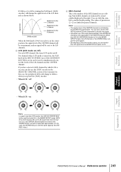
...LCR is on, you can click this case, the STEREO B bus is sent the same signal as the STEREO A bus.) Output functions Input functions Appendices PM5D/PM5D-RH Owner's Manual Reference section 243 You can also use the [PAN] encoder in the SELECTED CHANNEL section of the top panel. L R • ... signal from the MONITOR OUT jacks L/C/R. You can also use the LCR function, the USE AS CENTER BUS button must be turned On in the MIXER SETUP screen (SYS/ W.CLOCK function) (➥ p.201). Signal level L C R [PAN] encoder Signal sent to the C channel Signal sent to the L channel Signal ...
...LCR is on, you can click this case, the STEREO B bus is sent the same signal as the STEREO A bus.) Output functions Input functions Appendices PM5D/PM5D-RH Owner's Manual Reference section 243 You can also use the [PAN] encoder in the SELECTED CHANNEL section of the top panel. L R • ... signal from the MONITOR OUT jacks L/C/R. You can also use the LCR function, the USE AS CENTER BUS button must be turned On in the MIXER SETUP screen (SYS/ W.CLOCK function) (➥ p.201). Signal level L C R [PAN] encoder Signal sent to the C channel Signal sent to the L channel Signal ...
Owner's Manual
Page 244
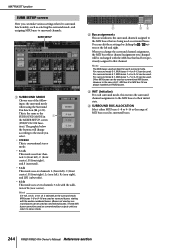
...of MIX buses used as surround buses, starting with the MIX bus that had been previously assigned to that are used as surround buses. 244 PM5D/PM5D-RH Owner's Manual Reference section For surround mode 3-1, MIX buses 1-4 or 9-13 can be used as conventional bus outputs until you return ... buses. (Buses not used as surround buses can be used as conventional buses.) These MIX buses cannot be used . However in 1 the MIXER SETUP screen (SYS/W.CLOCK func- MATRIX/ST function SURR SETUP screen Here you can make various settings related to surround functionality, such as FIXED ...
...of MIX buses used as surround buses, starting with the MIX bus that had been previously assigned to that are used as surround buses. 244 PM5D/PM5D-RH Owner's Manual Reference section For surround mode 3-1, MIX buses 1-4 or 9-13 can be used as conventional bus outputs until you return ... buses. (Buses not used as surround buses can be used as conventional buses.) These MIX buses cannot be used . However in 1 the MIXER SETUP screen (SYS/W.CLOCK func- MATRIX/ST function SURR SETUP screen Here you can make various settings related to surround functionality, such as FIXED ...


