

Owner's Manual
Page 5
...oscillators can be used for the monitor output, you can select (in addition to eight mute (on/off individually. • The M3000A-40C/M3000A-56C features a center master design that places the master section in the middle of 128 "scenes." By grouping the desired input channels... easy to switch the individual on /off status of input modules; 4 stereo and monaural (the M3000A-56C provides 56 monaural, the M3000A-40C provides 40 monaural, the M3000A-32 provides 32 monaural, and the M3000A-24 provides 24 monaural). Stereo output, 16 mix outputs, and 8 matrix outputs are provided.
...oscillators can be used for the monitor output, you can select (in addition to eight mute (on/off individually. • The M3000A-40C/M3000A-56C features a center master design that places the master section in the middle of 128 "scenes." By grouping the desired input channels... easy to switch the individual on /off status of input modules; 4 stereo and monaural (the M3000A-56C provides 56 monaural, the M3000A-40C provides 40 monaural, the M3000A-32 provides 32 monaural, and the M3000A-24 provides 24 monaural). Stereo output, 16 mix outputs, and 8 matrix outputs are provided.
Owner's Manual
Page 6
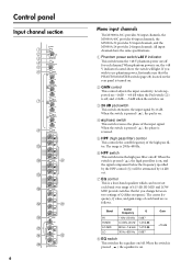
... M13 M14 0 10 M13/ M14 PAN M15 M16 M 0 10 M15/ M16 PRE 6 Mono input channels The M3000A-56C provides 56 input channels, the M3000A-40C provides 40 input channels, the M3000A-32 provides 32 input channels, and the M3000A-24 provides 24 input channels. B GAIN control This control adjusts the input sensitivity. Levels supported are...
... M13 M14 0 10 M13/ M14 PAN M15 M16 M 0 10 M15/ M16 PRE 6 Mono input channels The M3000A-56C provides 56 input channels, the M3000A-40C provides 40 input channels, the M3000A-32 provides 32 input channels, and the M3000A-24 provides 24 input channels. B GAIN control This control adjusts the input sensitivity. Levels supported are...

Owner's Manual
Page 7
... NOM SIGNAL VCA EQ f LO g f LO-MID g Q f HI-MID g Q f HI g 1 2 from VCA Master 7 8 CHECK ON from the input channel to MIX buses 1- 16. Input 1-24/1-40 +48V PHANTOM MASTER PAD HA 26dB GAIN +48V HPF HPF INSERT I M1-M8 switches These switch on/off the signal which is turned on /off...
... NOM SIGNAL VCA EQ f LO g f LO-MID g Q f HI-MID g Q f HI g 1 2 from VCA Master 7 8 CHECK ON from the input channel to MIX buses 1- 16. Input 1-24/1-40 +48V PHANTOM MASTER PAD HA 26dB GAIN +48V HPF HPF INSERT I M1-M8 switches These switch on/off the signal which is turned on /off...

Owner's Manual
Page 8
... on /off will be sent to the (ST) stereo bus. Control panel R L PAN R ST CHECK ON ON/ EDIT PEAK NOM SIGNAL Q S T V 10 1 5 2 0 3 5 4 10 5 20 6 30 7 40 8 50 VCA 60 PFL U W Q ST (stereo) switch When this case, you can use the PFL switch (W) to monitor the channel from the input channel to... the ST bus. T PEAK/NOM/SIGNAL indicators Three indicators show the level of the CHECK indicators. (The actual on the mode of the M3000A. This is convenient when you wish to verify the status of each channel stored in this switch is on /off status of the signal that...
... on /off will be sent to the (ST) stereo bus. Control panel R L PAN R ST CHECK ON ON/ EDIT PEAK NOM SIGNAL Q S T V 10 1 5 2 0 3 5 4 10 5 20 6 30 7 40 8 50 VCA 60 PFL U W Q ST (stereo) switch When this case, you can use the PFL switch (W) to monitor the channel from the input channel to... the ST bus. T PEAK/NOM/SIGNAL indicators Three indicators show the level of the CHECK indicators. (The actual on the mode of the M3000A. This is convenient when you wish to verify the status of each channel stored in this switch is on /off status of the signal that...

Owner's Manual
Page 9
... be affected by the corresponding VCA master fader(s). When you select a VCA group 1-8, the indicator located at the left of the input channel. Input 1-24/1-40 +48V PHANTOM MASTER PAD HA 26dB GAIN +48V HPF HPF INSERT I/O 4 Stage EQ PEAK NOM SIGNAL VCA EQ f LO g f LO-MID g Q f HI-MID g Q f HI g 1 2 from...
... be affected by the corresponding VCA master fader(s). When you select a VCA group 1-8, the indicator located at the left of the input channel. Input 1-24/1-40 +48V PHANTOM MASTER PAD HA 26dB GAIN +48V HPF HPF INSERT I/O 4 Stage EQ PEAK NOM SIGNAL VCA EQ f LO g f LO-MID g Q f HI-MID g Q f HI g 1 2 from...

Owner's Manual
Page 12
.... Control panel O L BAL R ST CHECK ON ON/ EDIT PEAK NOM SIGNAL N P Q S 10 1 5 2 0 3 5 4 10 5 R 20 6 30 7 40 8 50 VCA 60 PFL T N ST (stereo) switch When this switch and these indicators will depend on the mode of the M3000A. O BAL (balance) control This sets the left of each channel before you can use the...
.... Control panel O L BAL R ST CHECK ON ON/ EDIT PEAK NOM SIGNAL N P Q S 10 1 5 2 0 3 5 4 10 5 R 20 6 30 7 40 8 50 VCA 60 PFL T N ST (stereo) switch When this switch and these indicators will depend on the mode of the M3000A. O BAL (balance) control This sets the left of each channel before you can use the...

Owner's Manual
Page 14
... jacks, the MAS AFL bus, the ST bus, and the matrix. 0 0 0 0 0 0 5 5 5 5 5 5 10 10 10 10 10 10 20 20 20 20 20 20 40 40 40 40 40 40 0 0 5 5 10 10 20 20 40 40 AFL MIX 1/2 AFL MIX 3/4 AFL MIX 5/6 AFL MIX 7/8 AFL MIX 9/10 AFL MIX 11/12 AFL MIX 13/14 AFL MIX 15/16... 13/14 and 15/16 are on /off . The signal of the MAS AFL bus can turn each MIX OUT on the mode of the M3000A. These output channels control the signals of MIX OUT 1- 16. Control panel Mix section D ON/EDIT switches The function of these switches and indicators will...
... jacks, the MAS AFL bus, the ST bus, and the matrix. 0 0 0 0 0 0 5 5 5 5 5 5 10 10 10 10 10 10 20 20 20 20 20 20 40 40 40 40 40 40 0 0 5 5 10 10 20 20 40 40 AFL MIX 1/2 AFL MIX 3/4 AFL MIX 5/6 AFL MIX 7/8 AFL MIX 9/10 AFL MIX 11/12 AFL MIX 13/14 AFL MIX 15/16... 13/14 and 15/16 are on /off . The signal of the MAS AFL bus can turn each MIX OUT on the mode of the M3000A. These output channels control the signals of MIX OUT 1- 16. Control panel Mix section D ON/EDIT switches The function of these switches and indicators will...

Owner's Manual
Page 16
... 10 VCA 5 MUTE 0 NOMINAL 5 10 20 30 40 50 60 10 VCA 5 MUTE 0 NOMINAL 5 10 20 30 40 50 60 10 VCA 5 MUTE 0 NOMINAL 5 10 20 30 40 50 60 10 VCA 5 MUTE 0 NOMINAL 5 10 20 30 40 50 60 10 VCA 5 MUTE 0 NOMINAL 5 10 20 30 40 50 60 10 VCA 5 MUTE 0 NOMINAL 5 10... 20 30 40 50 60 10 VCA 5 MUTE 0 NOMINAL 5 10 20 30 40 50 60 10 VCA 5 MUTE 0 NOMINAL 5 10 20 30 40 50 60 A B C A VCA MUTE switches When these...
... 10 VCA 5 MUTE 0 NOMINAL 5 10 20 30 40 50 60 10 VCA 5 MUTE 0 NOMINAL 5 10 20 30 40 50 60 10 VCA 5 MUTE 0 NOMINAL 5 10 20 30 40 50 60 10 VCA 5 MUTE 0 NOMINAL 5 10 20 30 40 50 60 10 VCA 5 MUTE 0 NOMINAL 5 10 20 30 40 50 60 10 VCA 5 MUTE 0 NOMINAL 5 10... 20 30 40 50 60 10 VCA 5 MUTE 0 NOMINAL 5 10 20 30 40 50 60 10 VCA 5 MUTE 0 NOMINAL 5 10 20 30 40 50 60 A B C A VCA MUTE switches When these...

Owner's Manual
Page 17
A TO MATRIX STEREO A B CHECK ON C ON/EDIT AFL STEREO A 10 5 0 5 10 20 30 40 D 50 60 Control panel A TO MATRIX switch When this switch is on /off. qIn normal mode The ON/EDIT switch will turn on ( ), the indicator ... will be monitored from the MONITOR OUT jacks or from the MONITOR OUT jacks or the PHONES jack. This fader affects the level of the M3000A. B ON/EDIT switch The function of this switch is turned on, the signal of ST OUT A. When off status of ST OUT A stored in this...
A TO MATRIX STEREO A B CHECK ON C ON/EDIT AFL STEREO A 10 5 0 5 10 20 30 40 D 50 60 Control panel A TO MATRIX switch When this switch is on /off. qIn normal mode The ON/EDIT switch will turn on ( ), the indicator ... will be monitored from the MONITOR OUT jacks or from the MONITOR OUT jacks or the PHONES jack. This fader affects the level of the M3000A. B ON/EDIT switch The function of this switch is turned on, the signal of ST OUT A. When off status of ST OUT A stored in this...

Owner's Manual
Page 35
...reception oFF/GrP/on (Factory setting: on) This specifies whether or not control change messages will be transmitted or received. When this M3000A. ON/EDIT Switch 0 1 CH INPUT 1 2 CH INPUT 2 3 CH INPUT 3 4 CH INPUT 4 5 CH INPUT 5 6...INPUT 36 37 CH INPUT 37 38 CH INPUT 38 39 CH INPUT 39 40 CH INPUT 40 41 CH INPUT 41 42 CH INPUT 42 43 CH INPUT 43 44 CH... No. When this is assigned. In the same way, operating the ON/EDIT switches of the M3000A are connected, such a request will turn on the corresponding channel/bus, and a control change message...
...reception oFF/GrP/on (Factory setting: on) This specifies whether or not control change messages will be transmitted or received. When this M3000A. ON/EDIT Switch 0 1 CH INPUT 1 2 CH INPUT 2 3 CH INPUT 3 4 CH INPUT 4 5 CH INPUT 5 6...INPUT 36 37 CH INPUT 37 38 CH INPUT 38 39 CH INPUT 39 40 CH INPUT 40 41 CH INPUT 41 42 CH INPUT 42 43 CH INPUT 43 44 CH... No. When this is assigned. In the same way, operating the ON/EDIT switches of the M3000A are connected, such a request will turn on the corresponding channel/bus, and a control change message...

Owner's Manual
Page 38
... S 10 VCA MUTE 5 0 NOMINAL 5 10 20 30 40 50 60 10 VCA MUTE 5 0 NOMINAL 5 10 20 30 40 50 60 10 VCA MUTE 5 0 NOMINAL 5 10 20 30 40 50 60 10 VCA MUTE 5 0 NOMINAL 5 10 20 30 40 50 60 10 VCA MUTE 5 0 NOMINAL 5 10 20 30 40 50 60 10 VCA MUTE 5 0 NOMINAL 5 10... signals Control signals CH1 FADER INPUT 1 VCA MIX OUT CH 1 VCA GROUP SW 1 MATRIX STEREO OUT OUT VCA MASTER FADER 1 • The gain of the M3000A contains eight VCA master faders.
... S 10 VCA MUTE 5 0 NOMINAL 5 10 20 30 40 50 60 10 VCA MUTE 5 0 NOMINAL 5 10 20 30 40 50 60 10 VCA MUTE 5 0 NOMINAL 5 10 20 30 40 50 60 10 VCA MUTE 5 0 NOMINAL 5 10 20 30 40 50 60 10 VCA MUTE 5 0 NOMINAL 5 10 20 30 40 50 60 10 VCA MUTE 5 0 NOMINAL 5 10... signals Control signals CH1 FADER INPUT 1 VCA MIX OUT CH 1 VCA GROUP SW 1 MATRIX STEREO OUT OUT VCA MASTER FADER 1 • The gain of the M3000A contains eight VCA master faders.

Owner's Manual
Page 40
... without operating the faders. • By using this in which chorus 1-3 (inputs 12-14) are turned off, chorus 1-3 will be muted from VCA groups 4, 6, and 8. 40
... without operating the faders. • By using this in which chorus 1-3 (inputs 12-14) are turned off, chorus 1-3 will be muted from VCA groups 4, 6, and 8. 40

Owner's Manual
Page 42
... +48V DC is applied to MONITOR OUT CH INPUT PAD SW 26 dB CH INPUT GAIN control 44 dB variable ST CH INPUT GAIN control 40 dB variable (ST CH A INPUT) 30 dB variable (ST CH B INPUT) CH INPUT High Pass Filter 12 dB/octave roll-off below 20-400 Hz...
... +48V DC is applied to MONITOR OUT CH INPUT PAD SW 26 dB CH INPUT GAIN control 44 dB variable ST CH INPUT GAIN control 40 dB variable (ST CH A INPUT) 30 dB variable (ST CH B INPUT) CH INPUT High Pass Filter 12 dB/octave roll-off below 20-400 Hz...

Owner's Manual
Page 43
... Phone Jack *4 43 Output specifications Connection Actual Source Impedance For Use With Nominal Output Level Nominal Max before Clip CH INPUT (1~24) (1~32) (1~40) (1~56) 0 -60 26 0 -16 26 ST CH A INPUT -30 [L, R] (1~4) +10 ST CH B INPUT -20 [L, R] (1~4) +10 TALKBACK IN 2TR IN 1 [L, R] ...2TR IN 2 [L, R] CUE SUB IN [L, R] MATRIX SUB IN [L, R] STEREO SUB IN [L, R] MIX SUB IN (1~16) CH INSERT IN (1~24, 32, 40, 56) STEREO INSERT IN [L, R] MIX INSERT IN (1~16) 3 kΩ 5 kΩ 10 kΩ 10 kΩ 10 kΩ 10 kΩ 10 kΩ 50-600 Ω...
... Phone Jack *4 43 Output specifications Connection Actual Source Impedance For Use With Nominal Output Level Nominal Max before Clip CH INPUT (1~24) (1~32) (1~40) (1~56) 0 -60 26 0 -16 26 ST CH A INPUT -30 [L, R] (1~4) +10 ST CH B INPUT -20 [L, R] (1~4) +10 TALKBACK IN 2TR IN 1 [L, R] ...2TR IN 2 [L, R] CUE SUB IN [L, R] MATRIX SUB IN [L, R] STEREO SUB IN [L, R] MIX SUB IN (1~16) CH INSERT IN (1~24, 32, 40, 56) STEREO INSERT IN [L, R] MIX INSERT IN (1~16) 3 kΩ 5 kΩ 10 kΩ 10 kΩ 10 kΩ 10 kΩ 10 kΩ 50-600 Ω...