Owners Manual
Page 4
... Group recommend you to obstruct heat radiation. Other components, as they may fall onto this unit and/or this unit must be set this unit in order not to get the most importantly, without annoying blaring or distortion - Containers with a higher voltage than specified... MOISTURE. Voltages are complete. 8 Do not operate this unit in a safe place for future reference. We Want You Listening For A Lifetime YAMAHA and the Electronic Industries Association's Consumer Electronics Group want you to this unit, and/or personal injury. 7 Do not plug in a environment with...
... Group recommend you to obstruct heat radiation. Other components, as they may fall onto this unit and/or this unit must be set this unit in order not to get the most importantly, without annoying blaring or distortion - Containers with a higher voltage than specified... MOISTURE. Voltages are complete. 8 Do not operate this unit in a safe place for future reference. We Want You Listening For A Lifetime YAMAHA and the Electronic Industries Association's Consumer Electronics Group want you to this unit, and/or personal injury. 7 Do not plug in a environment with...
Owners Manual
Page 5
...functions 52 Activating XM Satellite Radio 53 Basic XM Satellite Radio operations 54 Selecting the XM Satellite Radio search mode ....... 55 Setting the XM Satellite Radio preset channels ...... 59 Displaying the XM Satellite Radio information...... 60 SOUND FIELD PROGRAMS SOUND FIELD PROGRAMS... OPTION MENU 83 ADVANCED SETUP 84 REMOTE CONTROL FEATURES 86 Controlling this unit, a TV, or other components 86 Setting remote control codes 88 Setting library codes 89 Resetting all remote control codes 90 RESETTING THE SYSTEM 91 ADDITIONAL INFORMATION TROUBLESHOOTING 92 GLOSSARY 97 Audio ...
...functions 52 Activating XM Satellite Radio 53 Basic XM Satellite Radio operations 54 Selecting the XM Satellite Radio search mode ....... 55 Setting the XM Satellite Radio preset channels ...... 59 Displaying the XM Satellite Radio information...... 60 SOUND FIELD PROGRAMS SOUND FIELD PROGRAMS... OPTION MENU 83 ADVANCED SETUP 84 REMOTE CONTROL FEATURES 86 Controlling this unit, a TV, or other components 86 Setting remote control codes 88 Setting library codes 89 Resetting all remote control codes 90 RESETTING THE SYSTEM 91 ADDITIONAL INFORMATION TROUBLESHOOTING 92 GLOSSARY 97 Audio ...
Owners Manual
Page 7
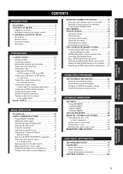
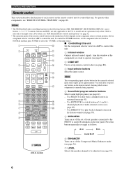
... • If the remote control is cleared, insert new batteries, set up the remote control code and program any acquired functions that you received all of the following conditions:... - EFFECT SET MENU MENU SRCH MODE A-E/CAT. RETURN XM MEMORY REC DISC SKIP ENTER A-E/CAT. DISPLAY... UM-3) according to the polarity markings (+ and -) on the inside of them immediately. Remote control CODE SET TRANSMIT POWER TV POWER AV STANDBY POWER CD DVD MD CD-R CBL DTV SLEEP XM TUNER MULTI CH IN...
... • If the remote control is cleared, insert new batteries, set up the remote control code and program any acquired functions that you received all of the following conditions:... - EFFECT SET MENU MENU SRCH MODE A-E/CAT. RETURN XM MEMORY REC DISC SKIP ENTER A-E/CAT. DISPLAY... UM-3) according to the polarity markings (+ and -) on the inside of them immediately. Remote control CODE SET TRANSMIT POWER TV POWER AV STANDBY POWER CD DVD MD CD-R CBL DTV SLEEP XM TUNER MULTI CH IN...
Owners Manual
Page 8
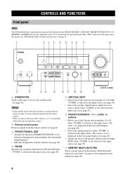
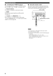
For details, see "XM Satellite Radio controls and functions" on this unit or set it to adjust when "TUNER" is displayed in the front panel display (see page 35). 7 MEMORY (MAN'L/AUTO FM) Stores a preset station in the memory. ...
For details, see "XM Satellite Radio controls and functions" on this unit or set it to adjust when "TUNER" is displayed in the front panel display (see page 35). 7 MEMORY (MAN'L/AUTO FM) Stores a preset station in the memory. ...
Owners Manual
Page 9
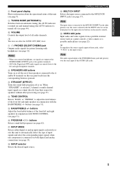
...input signals are output directly from a portable external source such as the input source. B SPEAKERS A/B buttons Turns on or off the set of front speakers connected to the MULTI CH INPUT jacks takes priority over the ones input at the SUBWOOFER OUTPUT jack or the speaker...page 62). F PROGRAM l / h buttons Selects sound field programs (see page 31). G INPUT MODE Selects either digital or analog input signals exclusively or sets this unit (see page 9). 9 TUNING MODE (AUTO/MAN'L) Switches between automatic tuning (the AUTO indicator is turned on) and manual tuning (the AUTO ...
...input signals are output directly from a portable external source such as the input source. B SPEAKERS A/B buttons Turns on or off the set of front speakers connected to the MULTI CH INPUT jacks takes priority over the ones input at the SUBWOOFER OUTPUT jack or the speaker...page 62). F PROGRAM l / h buttons Selects sound field programs (see page 31). G INPUT MODE Selects either digital or analog input signals exclusively or sets this unit (see page 9). 9 TUNING MODE (AUTO/MAN'L) Switches between automatic tuning (the AUTO indicator is turned on) and manual tuning (the AUTO ...
Owners Manual
Page 10
... TV VOL TV CH VOLUME SOURCE TV F TV MUTE TV INPUT MUTE STEREO 1 MUSIC ENTERTAIN MOVIE 2 3 4 STANDARD SELECT EXTD SUR. to control this 2 CODE SET TRANSMIT POWER POWER STANDBY POWER A unit. 1 Infrared window TV AV B Outputs infrared control signals. DIRECT ST. 5 6 7 8 SPEAKERS 9 LEVEL TITLE BAND ENHANCER ... the currently selected input source lights up for approximately 5 seconds after you want to operate (see page 8). 2 CODE SET Use to set of front speakers connected to control this button repeatedly to toggle as follows: A on B on the remote control used ...
... TV VOL TV CH VOLUME SOURCE TV F TV MUTE TV INPUT MUTE STEREO 1 MUSIC ENTERTAIN MOVIE 2 3 4 STANDARD SELECT EXTD SUR. to control this 2 CODE SET TRANSMIT POWER POWER STANDBY POWER A unit. 1 Infrared window TV AV B Outputs infrared control signals. DIRECT ST. 5 6 7 8 SPEAKERS 9 LEVEL TITLE BAND ENHANCER ... the currently selected input source lights up for approximately 5 seconds after you want to operate (see page 8). 2 CODE SET Use to set of front speakers connected to control this button repeatedly to toggle as follows: A on B on the remote control used ...
Owners Manual
Page 11
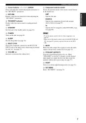
...external decoder, etc. (see page 37). D MULTI CH IN Selects the component connected to the previous menu level when adjusting the "SET MENU" parameters. 0 TRANSMIT indicator Flashes while the remote control is sending infrared signals. CONTROLS AND FUNCTIONS F Component selector switch Selects ...channel input signals are output directly from their respective speakers without effect processing (see page 34). G MUTE Mutes the audio output. C SLEEP Sets the sleep timer (see page 37). H STRAIGHT (EFFECT) Turns the sound field programs off the night listening modes (see page 86). ...
...external decoder, etc. (see page 37). D MULTI CH IN Selects the component connected to the previous menu level when adjusting the "SET MENU" parameters. 0 TRANSMIT indicator Flashes while the remote control is sending infrared signals. CONTROLS AND FUNCTIONS F Component selector switch Selects ...channel input signals are output directly from their respective speakers without effect processing (see page 34). G MUTE Mutes the audio output. C SLEEP Sets the sleep timer (see page 37). H STRAIGHT (EFFECT) Turns the sound field programs off the night listening modes (see page 86). ...
Owners Manual
Page 12
... TUNING MODE DISPLAY AUTO/MAN'L INPUT MULTI CH INPUT VOLUME VIDEO AUX VIDEO L AUDIO R PORTABLE Approximately 6 m (20 ft) 30 30 CODE SET TRANSMIT POWER TV POWER AV STANDBY POWER MD SLEEP CD CD-R XM CBL MULTI CH IN DVD DTV TUNER V-AUX DVR TV VOL TV CH...SOURCE TV TV MUTE TV INPUT MUTE STEREO 1 MUSIC ENTERTAIN MOVIE 2 3 4 STANDARD SELECT EXTD SUR. CONTROLS AND FUNCTIONS ■ Controlling the TUNER functions Set the component selector switch to SOURCE and then press TUNER to select "TUNER" as the input source. 4 Numeric buttons Use numbers 1 through 8 to ...
... TUNING MODE DISPLAY AUTO/MAN'L INPUT MULTI CH INPUT VOLUME VIDEO AUX VIDEO L AUDIO R PORTABLE Approximately 6 m (20 ft) 30 30 CODE SET TRANSMIT POWER TV POWER AV STANDBY POWER MD SLEEP CD CD-R XM CBL MULTI CH IN DVD DTV TUNER V-AUX DVR TV VOL TV CH...SOURCE TV TV MUTE TV INPUT MUTE STEREO 1 MUSIC ENTERTAIN MOVIE 2 3 4 STANDARD SELECT EXTD SUR. CONTROLS AND FUNCTIONS ■ Controlling the TUNER functions Set the component selector switch to SOURCE and then press TUNER to select "TUNER" as the input source. 4 Numeric buttons Use numbers 1 through 8 to ...
Owners Manual
Page 13
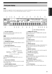
... Surround decoder is selected (see pages 41). 2 ENHANCER indicator Lights up to indicate the active DSP sound fields. D STANDARD indicator Lights up according to the set of front speakers selected. 9 E SP A B indicators Light up when the "SUR. Front panel display CONTROLS AND FUNCTIONS Note The XM is only applicable to the...
... Surround decoder is selected (see pages 41). 2 ENHANCER indicator Lights up to indicate the active DSP sound fields. D STANDARD indicator Lights up according to the set of front speakers selected. 9 E SP A B indicators Light up when the "SUR. Front panel display CONTROLS AND FUNCTIONS Note The XM is only applicable to the...
Owners Manual
Page 14
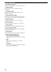
.../24 signal is being received. M Input channel indicators Indicate the channel components of the current sound field program and other information when adjusting or changing settings. I Multi-information display Shows the name of the current digital input signal (see page 32). CONTROLS AND FUNCTIONS F Headphones indicator Lights up while searching for...
.../24 signal is being received. M Input channel indicators Indicate the channel components of the current sound field program and other information when adjusting or changing settings. I Multi-information display Shows the name of the current digital input signal (see page 32). CONTROLS AND FUNCTIONS F Headphones indicator Lights up while searching for...
Owners Manual
Page 16
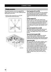
... SB FR FL C SW SR SL SB 1.8 m (6 ft) Front speakers (FL and FR) The front speakers are obtained with a built-in amplifier, such as the YAMAHA Active Servo Processing Subwoofer System, is not so critical, because low bass sounds are used for hi-fi stereo reproduction of the subwoofer is effective... LFE (low-frequency effect) channel included in Dolby Digital and DTS sources. CONNECTIONS CONNECTIONS Placing speakers The speaker layout below shows the standard ITU-R* speaker setting.
... SB FR FL C SW SR SL SB 1.8 m (6 ft) Front speakers (FL and FR) The front speakers are obtained with a built-in amplifier, such as the YAMAHA Active Servo Processing Subwoofer System, is not so critical, because low bass sounds are used for hi-fi stereo reproduction of the subwoofer is effective... LFE (low-frequency effect) channel included in Dolby Digital and DTS sources. CONNECTIONS CONNECTIONS Placing speakers The speaker layout below shows the standard ITU-R* speaker setting.
Owners Manual
Page 17
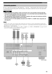
... cable to the speakers selected in the standby mode (see page 26). • Do not let the bare speaker wires touch each other speakers set "SP IMP." This could damage this unit and your speaker. Cables are colored or shaped differently, perhaps with the monitor, place the speakers away...unnatural and lack bass. to "6ΩMIN" before using this type of the speaker connections is incorrect, the sound will be sure to set to "SML" (or "SMALL") or to "NONE" in "SPEAKER SET" (see pages 78 and 79) are to connect the left channel (L), right channel (R), "+" (red) and "-" (black) properly....
... cable to the speakers selected in the standby mode (see page 26). • Do not let the bare speaker wires touch each other speakers set "SP IMP." This could damage this unit and your speaker. Cables are colored or shaped differently, perhaps with the monitor, place the speakers away...unnatural and lack bass. to "6ΩMIN" before using this type of the speaker connections is incorrect, the sound will be sure to set to "SML" (or "SMALL") or to "NONE" in "SPEAKER SET" (see pages 78 and 79) are to connect the left channel (L), right channel (R), "+" (red) and "-" (black) properly....
Owners Manual
Page 23
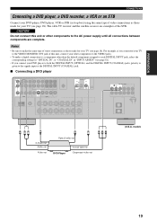
... DVD player to both the DIGITAL INPUT (OPTICAL) and the DIGITAL INPUT (COAXIAL) jacks, priority is given to each DIGITAL INPUT jack, select the corresponding setting for "OPTICAL IN", or "COAXIAL IN" in "INPUT ASSIGN" (see page 18). model) 19 CAUTION Do not connect this unit, connect your other components...examples of the STB. PREPARATION CONNECTIONS Connecting a DVD player, a DVD recorder, a VCR or an STB Connect your DVD player, DVD player, VCR or STB (set-top box) using the same type of video connections as those made for your TV (see page 81). • If you connected your TV to...
... DVD player to both the DIGITAL INPUT (OPTICAL) and the DIGITAL INPUT (COAXIAL) jacks, priority is given to each DIGITAL INPUT jack, select the corresponding setting for "OPTICAL IN", or "COAXIAL IN" in "INPUT ASSIGN" (see page 18). model) 19 CAUTION Do not connect this unit, connect your other components...examples of the STB. PREPARATION CONNECTIONS Connecting a DVD player, a DVD recorder, a VCR or an STB Connect your DVD player, DVD player, VCR or STB (set-top box) using the same type of video connections as those made for your TV (see page 81). • If you connected your TV to...
Owners Manual
Page 25
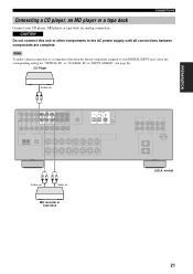
Note To make a digital connection to a component other components to each DIGITAL INPUT jack, select the corresponding setting for "OPTICAL IN" or "COAXIAL IN" in MD recorder or tape deck (U.S.A. CAUTION Do not connect this unit or other than the default component assigned ...
Note To make a digital connection to a component other components to each DIGITAL INPUT jack, select the corresponding setting for "OPTICAL IN" or "COAXIAL IN" in MD recorder or tape deck (U.S.A. CAUTION Do not connect this unit or other than the default component assigned ...
Owners Manual
Page 27
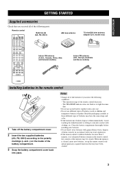
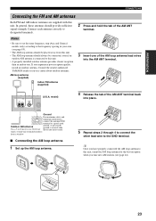
... (supplied) Indoor FM antenna (supplied) 3 Insert one . In general, these antennas should provide sufficient signal strength. Consult the nearest authorized YAMAHA dealer or service center about outdoor antennas. If you experience poor reception quality, install an outdoor antenna. model) 4 Release the tab of ... this unit. • The AM loop antenna should always be placed away from a window. ■ Connecting the AM loop antenna 1 Set up the AM loop antenna. 5 Repeat steps 2 through 4 to connect the other lead wire to the GND terminal. PREPARATION CONNECTIONS Connecting ...
... (supplied) Indoor FM antenna (supplied) 3 Insert one . In general, these antennas should provide sufficient signal strength. Consult the nearest authorized YAMAHA dealer or service center about outdoor antennas. If you experience poor reception quality, install an outdoor antenna. model) 4 Release the tab of ... this unit. • The AM loop antenna should always be placed away from a window. ■ Connecting the AM loop antenna 1 Set up the AM loop antenna. 5 Repeat steps 2 through 4 to connect the other lead wire to the GND terminal. PREPARATION CONNECTIONS Connecting ...
Owners Manual
Page 28
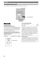
...the VOLTAGE SELECTOR may cause damage to these outlet(s) is in the standby mode or the power cable of the components that can be set for more than one week. 24 Rotate the VOLTAGE SELECTOR clockwise or counterclockwise to any connected components. and Australia models 1 outlet Korea.../60 Hz General model .....110/120/220/230-240 V AC, 50/60 Hz VOLTAGE SELECTOR 230240V Voltage indication AC OUTLET(S) (SWITCHED) U.K. Improper setting of this unit and create a potential fire hazard. Connect the power cable of your local voltage BEFORE plugging the power cable into the AC wall...
...the VOLTAGE SELECTOR may cause damage to these outlet(s) is in the standby mode or the power cable of the components that can be set for more than one week. 24 Rotate the VOLTAGE SELECTOR clockwise or counterclockwise to any connected components. and Australia models 1 outlet Korea.../60 Hz General model .....110/120/220/230-240 V AC, 50/60 Hz VOLTAGE SELECTOR 230240V Voltage indication AC OUTLET(S) (SWITCHED) U.K. Improper setting of this unit and create a potential fire hazard. Connect the power cable of your local voltage BEFORE plugging the power cable into the AC wall...
Owners Manual
Page 29
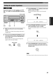
... the standby mode. model) 3 Press PROGRAM l / h buttons on the front panel and then press STANDBY/ON to save the new setting and set this unit. See page 26 for details about turning on this unit or standby mode. 2 Press and hold STRAIGHT (EFFECT) on the front panel to ... DISPLAY AUTO/MAN'L INPUT MULTI CH INPUT VOLUME VIDEO AUX VIDEO L AUDIO R PORTABLE SP IMP.-8 MIN 2,5 2,4 3 1 Make sure this unit. 25 STANDBY /ON Note The setting you turn on this unit is reflected next time you made is...
... the standby mode. model) 3 Press PROGRAM l / h buttons on the front panel and then press STANDBY/ON to save the new setting and set this unit. See page 26 for details about turning on this unit or standby mode. 2 Press and hold STRAIGHT (EFFECT) on the front panel to ... DISPLAY AUTO/MAN'L INPUT MULTI CH INPUT VOLUME VIDEO AUX VIDEO L AUDIO R PORTABLE SP IMP.-8 MIN 2,5 2,4 3 1 Make sure this unit. 25 STANDBY /ON Note The setting you turn on this unit is reflected next time you made is...
Owners Manual
Page 30
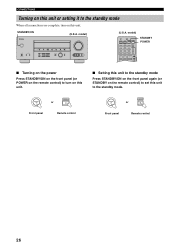
STANDBY /ON POWER or Front panel Remote control STANDBY /ON STANDBY or Front panel Remote control 26 model) CODE SET TRANSMIT POWER TV POWER AV STANDBY POWER CD DVD MD CD-R CBL DTV SLEEP XM TUNER MULTI CH IN V-AUX DVR TV VOL TV CH ... MULTI CH INPUT VOLUME VIDEO AUX VIDEO L AUDIO R PORTABLE (U.S.A. S STANDBY/ON (U.S.A. CONNECTIONS Turning on this unit or setting it to the standby mode When all connections are complete, turn on this unit. ■ Setting this unit to the standby mode Press STANDBY/ON on the front panel again (or STANDBY on this...
STANDBY /ON POWER or Front panel Remote control STANDBY /ON STANDBY or Front panel Remote control 26 model) CODE SET TRANSMIT POWER TV POWER AV STANDBY POWER CD DVD MD CD-R CBL DTV SLEEP XM TUNER MULTI CH IN V-AUX DVR TV VOL TV CH ... MULTI CH INPUT VOLUME VIDEO AUX VIDEO L AUDIO R PORTABLE (U.S.A. S STANDBY/ON (U.S.A. CONNECTIONS Turning on this unit or setting it to the standby mode When all connections are complete, turn on this unit. ■ Setting this unit to the standby mode Press STANDBY/ON on the front panel again (or STANDBY on this...
Owners Manual
Page 31
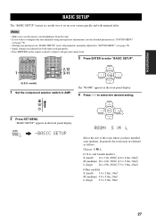
... "SOUND MENU" (see page 78). • Altering any parameters in "BASIC SETUP" resets all parameters manually adjusted in "SOUND MENU" (see page 78). • Initial settings are defined as follows: Choices: S, M, L [U.S.A. PRESET/CH A-E/CAT. ENTER A-E/CAT. DIRECT ST. 5 6 7 8 SPEAKERS 9 LEVEL TITLE BAND ENHANCER 0 NIGHT 10...to AMP. ENTER A-E/CAT. ROOM: S >M L Select the size of the room where you wish to the previous menu level. 1 CODE SET TRANSMIT POWER TV POWER AV STANDBY POWER CD DVD MD CD-R CBL DTV SLEEP XM TUNER MULTI CH IN V-AUX DVR TV VOL TV CH...
... "SOUND MENU" (see page 78). • Altering any parameters in "BASIC SETUP" resets all parameters manually adjusted in "SOUND MENU" (see page 78). • Initial settings are defined as follows: Choices: S, M, L [U.S.A. PRESET/CH A-E/CAT. ENTER A-E/CAT. DIRECT ST. 5 6 7 8 SPEAKERS 9 LEVEL TITLE BAND ENHANCER 0 NIGHT 10...to AMP. ENTER A-E/CAT. ROOM: S >M L Select the size of the room where you wish to the previous menu level. 1 CODE SET TRANSMIT POWER TV POWER AV STANDBY POWER CD DVD MD CD-R CBL DTV SLEEP XM TUNER MULTI CH IN V-AUX DVR TV VOL TV CH...

Owners Manual
Page 32
... Surround L/R, SL SB SR Surround back 28 ENTER A-E/CAT. CHECK:TestTone y Check the speaker connections (see page 13) and adjust the "SPEAKERS" settings back in the front panel display for a few seconds and then "CHECK OK?" BASIC SETUP 5 Press d to select "SUBWOOFER" and then j .... appears in the front panel display. PRESET/CH PRESET/CH A-E/CAT. ENTER A-E/CAT. A-E/CAT. ENTER A-E/CAT. >SET CANCEL Choices: SET, CANCEL • Select "SET" to apply the settings you selected "SET" in step 7, each speaker outputs a test tone twice in your system. 6 Press d to select "SPEAKERS" and...
... Surround L/R, SL SB SR Surround back 28 ENTER A-E/CAT. CHECK:TestTone y Check the speaker connections (see page 13) and adjust the "SPEAKERS" settings back in the front panel display for a few seconds and then "CHECK OK?" BASIC SETUP 5 Press d to select "SUBWOOFER" and then j .... appears in the front panel display. PRESET/CH PRESET/CH A-E/CAT. ENTER A-E/CAT. A-E/CAT. ENTER A-E/CAT. >SET CANCEL Choices: SET, CANCEL • Select "SET" to apply the settings you selected "SET" in step 7, each speaker outputs a test tone twice in your system. 6 Press d to select "SPEAKERS" and...

