
Owners Manual
Page 2
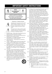
Do not use liquid cleaners or aerosol cleaners. 6 Attachments - in the cabinet are unable to the operating instructions. 12 Grounding or Polarization - Quick stops, excessive force, and uneven surfaces may fall into the product, c) If the product has been exposed to rain or water, i This product should still fail to fit, contact your electrician to the product. If you to the presence of any kind into this can fall , causing serious injury to a child or adult, and serious damage to replace your product dealer or local power company. This plug will prevent damage to ...
Do not use liquid cleaners or aerosol cleaners. 6 Attachments - in the cabinet are unable to the operating instructions. 12 Grounding or Polarization - Quick stops, excessive force, and uneven surfaces may fall into the product, c) If the product has been exposed to rain or water, i This product should still fail to fit, contact your electrician to the product. If you to the presence of any kind into this can fall , causing serious injury to a child or adult, and serious damage to replace your product dealer or local power company. This plug will prevent damage to ...
Owners Manual
Page 3
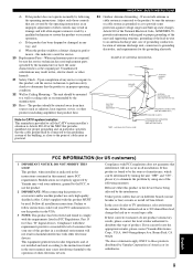
...GROUNDING CONDUCTORS (NEC SECTION 810-21) GROUND CLAMPS POWER SERVICE GROUNDING ELECTRODE SYSTEM (NEC ART 250. Modifications not expressly approved by Yamaha may cause interference harmful to Article 820-40 of the lead-in the users manual, may void your FCC authorization to provide...can be situated away from heat sources such as an improper adjustment of interference, which can not locate the appropriate retailer, please contact Yamaha Electronics Corp., U.S.A. 6660 Orangethorpe Ave, Buena Park, CA 90620. d) If the product does not operate normally by following measures: ...
...GROUNDING CONDUCTORS (NEC SECTION 810-21) GROUND CLAMPS POWER SERVICE GROUNDING ELECTRODE SYSTEM (NEC ART 250. Modifications not expressly approved by Yamaha may cause interference harmful to Article 820-40 of the lead-in the users manual, may void your FCC authorization to provide...can be situated away from heat sources such as an improper adjustment of interference, which can not locate the appropriate retailer, please contact Yamaha Electronics Corp., U.S.A. 6660 Orangethorpe Ave, Buena Park, CA 90620. d) If the product does not operate normally by following measures: ...
Owners Manual
Page 4
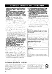
... not expose this unit in order not to liquid dripping or splashing. This state is needed. We Want You Listening For A Lifetime YAMAHA and the Electronic Industries Association's Consumer Electronics Group want you to avoid prolonged exposure from cold to use of plug to this unit near... power plug from use this unit for future reference. 2 Install this Owner's Manual in a well ventilated, cool, dry, clean place - YAMAHA will not be reached easily. 17 Be sure to read this might damage the finish. FOR CANADIAN CUSTOMERS To prevent electric shock, match wide blade...
... not expose this unit in order not to liquid dripping or splashing. This state is needed. We Want You Listening For A Lifetime YAMAHA and the Electronic Industries Association's Consumer Electronics Group want you to avoid prolonged exposure from cold to use of plug to this unit near... power plug from use this unit for future reference. 2 Install this Owner's Manual in a well ventilated, cool, dry, clean place - YAMAHA will not be reached easily. 17 Be sure to read this might damage the finish. FOR CANADIAN CUSTOMERS To prevent electric shock, match wide blade...

Owners Manual
Page 5
INTRODUCTION PREPARATION CONTENTS INTRODUCTION FEATURES 2 GETTING STARTED 3 Supplied accessories 3 Installing batteries in the remote control 3 CONTROLS AND FUNCTIONS 4 Front panel 4 Remote control 6 Using the remote control 7 Front panel display 8 Rear panel 9 PREPARATION CONNECTIONS 10 Placing speakers 10 Connecting speakers 11 Information on jacks and cable plugs 13 Connecting video components 14 Connecting audio components 16 Connecting the FM and AM antennas 17 Connecting the power cable 18 Turning on the power 18 SETUP 19 ADVANCED OPERATION ADVANCED OPERATIONS 31 ...
INTRODUCTION PREPARATION CONTENTS INTRODUCTION FEATURES 2 GETTING STARTED 3 Supplied accessories 3 Installing batteries in the remote control 3 CONTROLS AND FUNCTIONS 4 Front panel 4 Remote control 6 Using the remote control 7 Front panel display 8 Rear panel 9 PREPARATION CONNECTIONS 10 Placing speakers 10 Connecting speakers 11 Information on jacks and cable plugs 13 Connecting video components 14 Connecting audio components 16 Connecting the FM and AM antennas 17 Connecting the power cable 18 Turning on the power 18 SETUP 19 ADVANCED OPERATION ADVANCED OPERATIONS 31 ...
Owners Manual
Page 6
FEATURES FEATURES Built-in parentheses. • This manual is given in 6-channel power amplifier ◆ Minimum RMS output power per channel [Front, center, and surround channels] 80 W (1 kHz, 0.1% THD, 6 Ω) 110 W (1 kHz, 10% THD, 6 Ω) [Subwoofer channel] 110 W (50 Hz, 6 Ω) Decoders for multi-channel surround sound ◆ Dolby Digital decoder ◆ Dolby Pro Logic/Dolby Pro Logic II decoder ◆ DTS decoder Sophisticated AM/FM tuner ◆ 40-station random and direct preset tuning ◆ Automatic preset tuning ◆ Preset station shifting capability (...
FEATURES FEATURES Built-in parentheses. • This manual is given in 6-channel power amplifier ◆ Minimum RMS output power per channel [Front, center, and surround channels] 80 W (1 kHz, 0.1% THD, 6 Ω) 110 W (1 kHz, 10% THD, 6 Ω) [Subwoofer channel] 110 W (50 Hz, 6 Ω) Decoders for multi-channel surround sound ◆ Dolby Digital decoder ◆ Dolby Pro Logic/Dolby Pro Logic II decoder ◆ DTS decoder Sophisticated AM/FM tuner ◆ 40-station random and direct preset tuning ◆ Automatic preset tuning ◆ Preset station shifting capability (...

Owners Manual
Page 7
Read the packaging carefully as alkaline and manganese batteries) together. Avoid touching the leaked material or letting it come into place. 3 English Clean the battery compartment thoroughly before installing new batteries. • Do not throw away batteries with clothing, etc. Notes • Change all of the battery compartment. 3 Snap the battery compartment cover back into contact with general house waste; dispose of them immediately. Remote control STANDBY POWER CD MD/CD-R TUNER SLEEP DVD DTV/CBL VCR V-AUX TUNER P1 P2 P3 P4 P5 P6 A/B/C/D/E P7 P8 ...
Read the packaging carefully as alkaline and manganese batteries) together. Avoid touching the leaked material or letting it come into place. 3 English Clean the battery compartment thoroughly before installing new batteries. • Do not throw away batteries with clothing, etc. Notes • Change all of the battery compartment. 3 Snap the battery compartment cover back into contact with general house waste; dispose of them immediately. Remote control STANDBY POWER CD MD/CD-R TUNER SLEEP DVD DTV/CBL VCR V-AUX TUNER P1 P2 P3 P4 P5 P6 A/B/C/D/E P7 P8 ...
Owners Manual
Page 8
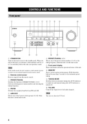
Note This does not affect the OUT level. 4 When you turn on this unit, you will hear a click and there will be a 4 to 5-second delay before this button for more than 3 seconds to start automatic preset tuning. 9 TUNING MODE Switches between FM and AM. 5 A/B/C/D/E Selects one of the 5 preset station groups (A to E) when this unit is in the tuner mode. 6 PRESET/TUNING l / h Selects one of the preset station numbers (1 to 8) or the tuning frequency when this unit is in the memory. Hold down this unit can reproduce sound. Note In the standby mode, this unit consumes a small amount of...
Note This does not affect the OUT level. 4 When you turn on this unit, you will hear a click and there will be a 4 to 5-second delay before this button for more than 3 seconds to start automatic preset tuning. 9 TUNING MODE Switches between FM and AM. 5 A/B/C/D/E Selects one of the 5 preset station groups (A to E) when this unit is in the tuner mode. 6 PRESET/TUNING l / h Selects one of the preset station numbers (1 to 8) or the tuning frequency when this unit is in the memory. Hold down this unit can reproduce sound. Note In the standby mode, this unit consumes a small amount of...
Owners Manual
Page 9
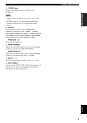
PROGRAM l / h Selects the surround mode. CONTROLS AND FUNCTIONS English 5 B STEREO Switches between normal stereo and DSP effect reproduction. When you connect headphones, no signals are output to the speakers. • All Dolby Digital and DTS audio signals (except the LFE channel) are mixed down all Dolby Digital and DTS signals (except the LFE channel) as well as those 2-channel signals without effect sounds to the front left and right speakers in conjunction with TONE CONTROL. C TONE CONTROL Adjusts the bass/treble balance of the front left and right headphone channels. ...
PROGRAM l / h Selects the surround mode. CONTROLS AND FUNCTIONS English 5 B STEREO Switches between normal stereo and DSP effect reproduction. When you connect headphones, no signals are output to the speakers. • All Dolby Digital and DTS audio signals (except the LFE channel) are mixed down all Dolby Digital and DTS signals (except the LFE channel) as well as those 2-channel signals without effect sounds to the front left and right speakers in conjunction with TONE CONTROL. C TONE CONTROL Adjusts the bass/treble balance of the front left and right headphone channels. ...
Owners Manual
Page 10
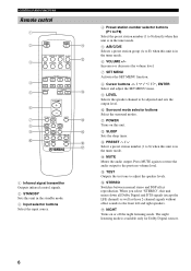
C PRESET u / d Select a preset station number (1 to 8) when this unit is in the tuner mode. E TEST Outputs the test tone to the previous volume level. G NIGHT Turns on this unit. CONTROLS AND FUNCTIONS Remote control 1 2 STANDBY POWER A 3 CD MD/CD-R TUNER SLEEP DVD DTV/CBL VCR V-AUX B 4 5 6 7 8 9 0 TUNER P1 P2 P3 P4 P5 P6 A/B/C/D/E P7 P8 PRESET VOLUME SET MENU MUTE ENTER LEVEL TEST HALL JAZZ ROCK PL 5 STEREO NIGHT STEREO C D E F G 1 Infrared signal transmitter Outputs infrared control signals. 2 STANDBY Sets this unit in the standby mode. 3 Input selector ...
C PRESET u / d Select a preset station number (1 to 8) when this unit is in the tuner mode. E TEST Outputs the test tone to the previous volume level. G NIGHT Turns on this unit. CONTROLS AND FUNCTIONS Remote control 1 2 STANDBY POWER A 3 CD MD/CD-R TUNER SLEEP DVD DTV/CBL VCR V-AUX B 4 5 6 7 8 9 0 TUNER P1 P2 P3 P4 P5 P6 A/B/C/D/E P7 P8 PRESET VOLUME SET MENU MUTE ENTER LEVEL TEST HALL JAZZ ROCK PL 5 STEREO NIGHT STEREO C D E F G 1 Infrared signal transmitter Outputs infrared control signals. 2 STANDBY Sets this unit in the standby mode. 3 Input selector ...

Owners Manual
Page 11
INTRODUCTION Using the remote control The remote control transmits a directional infrared beam. places of high humidity, such as near a bath - dusty places CONTROLS AND FUNCTIONS English 7 places of high temperature, such as near a heater or stove - places of conditions: - Be sure to aim the remote control directly at the remote control sensor on the front panel during operation. 30º 30º Approximately 6 m (20 ft) Notes • Do not spill water or other liquids on the remote control. • Do not drop the remote control. • Do not leave or store the ...
INTRODUCTION Using the remote control The remote control transmits a directional infrared beam. places of high humidity, such as near a bath - dusty places CONTROLS AND FUNCTIONS English 7 places of high temperature, such as near a heater or stove - places of conditions: - Be sure to aim the remote control directly at the remote control sensor on the front panel during operation. 30º 30º Approximately 6 m (20 ft) Notes • Do not spill water or other liquids on the remote control. • Do not drop the remote control. • Do not leave or store the ...
Owners Manual
Page 12
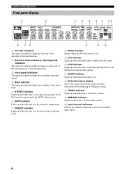
D MEMORY indicator Flashes to the current band. 5 STEREO indicator Lights up when this unit is receiving a strong signal for an FM stereo broadcast while the AUTO indicator is lit. 6 AUTO indicator Lights up when this unit is in the automatic tuning mode. 7 PRESET indicator Lights up when this unit is in the preset station selecting mode. 8 MUTE indicator Flashes while the MUTE function is on . E Input channel indicators Indicate the channel components of the surround mode or the listening mode. 3 Input signal indicators The respective indicator lights up according to the input signal...
D MEMORY indicator Flashes to the current band. 5 STEREO indicator Lights up when this unit is receiving a strong signal for an FM stereo broadcast while the AUTO indicator is lit. 6 AUTO indicator Lights up when this unit is in the automatic tuning mode. 7 PRESET indicator Lights up when this unit is in the preset station selecting mode. 8 MUTE indicator Flashes while the MUTE function is on . E Input channel indicators Indicate the channel components of the surround mode or the listening mode. 3 Input signal indicators The respective indicator lights up according to the input signal...
Owners Manual
Page 13
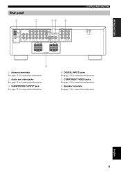
English 9 INTRODUCTION Rear panel 1 2 34 5 VIDEO AM ANT GND 75Ω UNBAL. FM ANT TUNER L R IN OUT MD/CD-R AUDIO DVD DTV/CBL V-AUX IN OUT VCR SURROUND SUB R L WOOFER + + MONITOR OUT Y OPTICAL COAXIAL PB SUB CD WOOFER DTV/CBL DVD OUTPUT DIGITAL INPUT CENTER FRONT R L PR DVD DTV/CBL MONITOR OUT COMPONENT VIDEO + + - - - - 6ΩMIN./SPEAKER CLASS 2 WIRING SPEAKERS 6ΩMIN./SPEAKER CONTROLS AND FUNCTIONS 6 1 Antenna terminals See page 17 for connection information. 2 Audio and video jacks See page 13 for connection information. 3 SUBWOOFER ...
English 9 INTRODUCTION Rear panel 1 2 34 5 VIDEO AM ANT GND 75Ω UNBAL. FM ANT TUNER L R IN OUT MD/CD-R AUDIO DVD DTV/CBL V-AUX IN OUT VCR SURROUND SUB R L WOOFER + + MONITOR OUT Y OPTICAL COAXIAL PB SUB CD WOOFER DTV/CBL DVD OUTPUT DIGITAL INPUT CENTER FRONT R L PR DVD DTV/CBL MONITOR OUT COMPONENT VIDEO + + - - - - 6ΩMIN./SPEAKER CLASS 2 WIRING SPEAKERS 6ΩMIN./SPEAKER CONTROLS AND FUNCTIONS 6 1 Antenna terminals See page 17 for connection information. 2 Audio and video jacks See page 13 for connection information. 3 SUBWOOFER ...

Owners Manual
Page 14
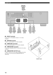
FL C FR 30˚ SL SR 60˚ SL 80˚ SR Front speakers (FR and FL) The front speakers are used for effect and surround sounds. Place the speaker centrally between the front speakers and as close to place the subwoofer near the front speakers. Place these speakers an equal distance from the ideal listening position. CONNECTIONS CONNECTIONS Placing speakers The speaker layout below shows the standard ITU-R* speaker setting. You can do without it. Surround speakers (SR and SL) The surround speakers are used for the main source sound plus effect sounds. ...
FL C FR 30˚ SL SR 60˚ SL 80˚ SR Front speakers (FR and FL) The front speakers are used for effect and surround sounds. Place the speaker centrally between the front speakers and as close to place the subwoofer near the front speakers. Place these speakers an equal distance from the ideal listening position. CONNECTIONS CONNECTIONS Placing speakers The speaker layout below shows the standard ITU-R* speaker setting. You can do without it. Surround speakers (SR and SL) The surround speakers are used for the main source sound plus effect sounds. ...
Owners Manual
Page 15
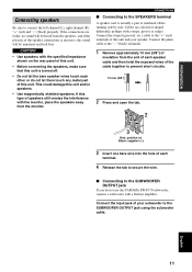
... the speakers away from the speakers, and if the polarity of the speaker connections is actually a pair of each other or do not use the YAMAHA SW-P170 subwoofer, connect a subwoofer with a stripe, groove or ridges. CONNECTIONS ■ Connecting to the SUBWOOFER OUTPUT jack using the subwoofer cable. Connect the plain...
... the speakers away from the speakers, and if the polarity of the speaker connections is actually a pair of each other or do not use the YAMAHA SW-P170 subwoofer, connect a subwoofer with a stripe, groove or ridges. CONNECTIONS ■ Connecting to the SUBWOOFER OUTPUT jack using the subwoofer cable. Connect the plain...
Owners Manual
Page 16
... terminals. ■ CENTER terminals Connect a center speaker (3) to these terminals. 16 ■ SURROUND terminals Connect surround speakers (4, 5) to these terminals. 2 ■ SUBWOOFER terminals 3 4 Connect the YAMAHA SW-P170 subwoofer (6) to these terminals. ■ SUBWOOFER OUTPUT jack Connect a subwoofer with built-in amplifier (6) to this jack when you do not use the...
... terminals. ■ CENTER terminals Connect a center speaker (3) to these terminals. 16 ■ SURROUND terminals Connect surround speakers (4, 5) to these terminals. 2 ■ SUBWOOFER terminals 3 4 Connect the YAMAHA SW-P170 subwoofer (6) to these terminals. ■ SUBWOOFER OUTPUT jack Connect a subwoofer with built-in amplifier (6) to this jack when you do not use the...
Owners Manual
Page 17
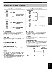
Connect red plugs to the right jacks and white plugs to input PCM, Dolby Digital and DTS bitstreams. All digital input jacks are output only at the analog AUDIO OUT jacks. ■ Video jacks This unit has two types of audio jacks (analog audio, digital audio coaxial, and digital audio optical). Thus audio signals input at the analog jacks are compatible with 96 kHz sampling digital signals. • This unit handles digital and analog signals independently. Video signal flow for MONITOR OUT Input Output (MONITOR OUT) COMPONENT VIDEO VIDEO English 13 COMPONENT VIDEO jacks For...
Connect red plugs to the right jacks and white plugs to input PCM, Dolby Digital and DTS bitstreams. All digital input jacks are output only at the analog AUDIO OUT jacks. ■ Video jacks This unit has two types of audio jacks (analog audio, digital audio coaxial, and digital audio optical). Thus audio signals input at the analog jacks are compatible with 96 kHz sampling digital signals. • This unit handles digital and analog signals independently. Video signal flow for MONITOR OUT Input Output (MONITOR OUT) COMPONENT VIDEO VIDEO English 13 COMPONENT VIDEO jacks For...
Owners Manual
Page 18
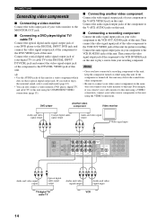
Connect the audio signal output jacks on your component to the VCR IN AUDIO jacks of this unit for a video component which does not have connected a recording component to this unit, keep the component turned on while using the COMPONENT VIDEO connections (page 15). ■ Connecting another video component Connect the video signal output jack of your digital TV or cable TV to the DIGITAL INPUT DTV/CBL jack and connect the video signal output jack of the component to the V-AUX VIDEO jack on this unit to play a source from other components. • Be sure to connect your video ...
Connect the audio signal output jacks on your component to the VCR IN AUDIO jacks of this unit for a video component which does not have connected a recording component to this unit, keep the component turned on while using the COMPONENT VIDEO connections (page 15). ■ Connecting another video component Connect the video signal output jack of your digital TV or cable TV to the DIGITAL INPUT DTV/CBL jack and connect the video signal output jack of the component to the V-AUX VIDEO jack on this unit to play a source from other components. • Be sure to connect your video ...
Owners Manual
Page 19
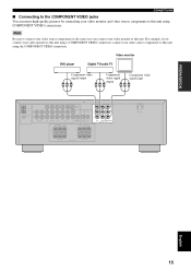
PREPARATION CONNECTIONS ■ Connecting to the COMPONENT VIDEO jacks You can enjoy high-quality pictures by connecting your video monitor and video source components to this unit. FM ANT TUNER L R IN OUT MD/CD-R AUDIO DVD DTV/CBL V-AUX IN OUT VCR SURROUND SUB R L WOOFER + + MONITOR OUT Y OPTICAL COAXIAL PB SUB CD WOOFER DTV/CBL DVD OUTPUT DIGITAL INPUT CENTER FRONT R L PR DVD DTV/CBL MONITOR OUT COMPONENT VIDEO + + - - - - 6ΩMIN./SPEAKER CLASS 2 WIRING SPEAKERS 6ΩMIN./SPEAKER English 15 Video monitor DVD player Digital TV/cable TV ...
PREPARATION CONNECTIONS ■ Connecting to the COMPONENT VIDEO jacks You can enjoy high-quality pictures by connecting your video monitor and video source components to this unit. FM ANT TUNER L R IN OUT MD/CD-R AUDIO DVD DTV/CBL V-AUX IN OUT VCR SURROUND SUB R L WOOFER + + MONITOR OUT Y OPTICAL COAXIAL PB SUB CD WOOFER DTV/CBL DVD OUTPUT DIGITAL INPUT CENTER FRONT R L PR DVD DTV/CBL MONITOR OUT COMPONENT VIDEO + + - - - - 6ΩMIN./SPEAKER CLASS 2 WIRING SPEAKERS 6ΩMIN./SPEAKER English 15 Video monitor DVD player Digital TV/cable TV ...
Owners Manual
Page 20
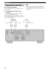
Note Once you have connected a recording component to this unit, keep the component turned on while using this unit. CONNECTIONS Connecting audio components ■ Connecting a CD player Connect the output jacks of your CD player to the CD jacks of this unit. Connect the output jacks of your CD recorder or MD recorder to play a source from other components. ■ Connecting a CD recorder or MD recorder Connect the input jacks of your recording component. FM ANT TUNER L R IN OUT MD/CD-R AUDIO DVD DTV/CBL V-AUX IN OUT VCR SURROUND SUB R L WOOFER + + ...
Note Once you have connected a recording component to this unit, keep the component turned on while using this unit. CONNECTIONS Connecting audio components ■ Connecting a CD player Connect the output jacks of your CD player to the CD jacks of this unit. Connect the output jacks of your CD recorder or MD recorder to play a source from other components. ■ Connecting a CD recorder or MD recorder Connect the input jacks of your recording component. FM ANT TUNER L R IN OUT MD/CD-R AUDIO DVD DTV/CBL V-AUX IN OUT VCR SURROUND SUB R L WOOFER + + ...
Owners Manual
Page 21
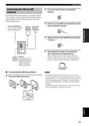
... tab of vinyl-covered wire extended outdoors from this unit. Outdoor AM antenna Use a 5 to 10 m (16 to the GND terminal. Consult the nearest authorized YAMAHA dealer or service center about outdoor antennas. • The AM loop antenna should provide sufficient signal strength. AM ANT GND 75Ω UNBAL. FM ANT...
... tab of vinyl-covered wire extended outdoors from this unit. Outdoor AM antenna Use a 5 to 10 m (16 to the GND terminal. Consult the nearest authorized YAMAHA dealer or service center about outdoor antennas. • The AM loop antenna should provide sufficient signal strength. AM ANT GND 75Ω UNBAL. FM ANT...