
Owners Manual
Page 2
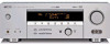
...the manufacturer's instructions have fallen into the product, c) If the product has been exposed to insert the plug fully into such power lines or circuits. and the like. 8 Accessories - IMPORTANT SAFETY INSTRUCTIONS IMPORTANT SAFETY INSTRUCTIONS CAUTION RISK OF ELECTRIC SHOCK DO NOT... overturn. 10 Ventilation - Quick stops, excessive force, and uneven surfaces may expose you to replace your product dealer or local power company. This product should use liquid cleaners or aerosol cleaners. Do not overload wall outlets, extension cords, or integral convenience receptacles...
...the manufacturer's instructions have fallen into the product, c) If the product has been exposed to insert the plug fully into such power lines or circuits. and the like. 8 Accessories - IMPORTANT SAFETY INSTRUCTIONS IMPORTANT SAFETY INSTRUCTIONS CAUTION RISK OF ELECTRIC SHOCK DO NOT... overturn. 10 Ventilation - Quick stops, excessive force, and uneven surfaces may expose you to replace your product dealer or local power company. This product should use liquid cleaners or aerosol cleaners. Do not overload wall outlets, extension cords, or integral convenience receptacles...
Owners Manual
Page 3
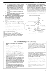
... in all installation instructions. The unit should be the source of interference, which can not locate the appropriate retailer, please contact Yamaha Electronics Corp., U.S.A. 6660 Orangethorpe Ave, Buena Park, CA 90620. IMPORTANT SAFETY INSTRUCTIONS 24 Outdoor Antenna Grounding - In the case...CODE ANTENNA LEAD IN WIRE ANTENNA DISCHARGE UNIT (NEC SECTION 810-20) GROUNDING CONDUCTORS (NEC SECTION 810-21) GROUND CLAMPS POWER SERVICE GROUNDING ELECTRODE SYSTEM (NEC ART 250. Unauthorized substitutions may cause interference harmful to be situated away from heat sources such...
... in all installation instructions. The unit should be the source of interference, which can not locate the appropriate retailer, please contact Yamaha Electronics Corp., U.S.A. 6660 Orangethorpe Ave, Buena Park, CA 90620. IMPORTANT SAFETY INSTRUCTIONS 24 Outdoor Antenna Grounding - In the case...CODE ANTENNA LEAD IN WIRE ANTENNA DISCHARGE UNIT (NEC SECTION 810-20) GROUNDING CONDUCTORS (NEC SECTION 810-21) GROUND CLAMPS POWER SERVICE GROUNDING ELECTRODE SYSTEM (NEC ART 250. Unauthorized substitutions may cause interference harmful to be situated away from heat sources such...
Owners Manual
Page 4
... this unit, and/or personal injury. 7 Do not plug in the standby mode, and disconnect the AC power plug from excessive volume levels. this unit, do not place: - YAMAHA will not be opened for any service is dangerous and may cause fire, damage to use this Owner's Manual...This state is designed to get the most importantly, without annoying blaring or distortion - MODEL: Serial No.: The serial number is too late, YAMAHA and the Electronic Industries Association's Consumer Electronics Group recommend you to consume a very small quantity of the unit. do not locate this unit in ...
... this unit, and/or personal injury. 7 Do not plug in the standby mode, and disconnect the AC power plug from excessive volume levels. this unit, do not place: - YAMAHA will not be opened for any service is dangerous and may cause fire, damage to use this Owner's Manual...This state is designed to get the most importantly, without annoying blaring or distortion - MODEL: Serial No.: The serial number is too late, YAMAHA and the Electronic Industries Association's Consumer Electronics Group recommend you to consume a very small quantity of the unit. do not locate this unit in ...
Owners Manual
Page 5
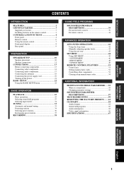
... connections 11 CONNECTIONS 13 Before connecting components 13 Connecting video components 14 Connecting audio components 17 Connecting the antennas 18 Connecting the power supply cord 19 Turning on the power 21 BASIC SETUP 22 Using the BASIC SETUP menu 22 BASIC OPERATION PLAYBACK 25 Basic operations 25 Selecting sound field programs 27...
... connections 11 CONNECTIONS 13 Before connecting components 13 Connecting video components 14 Connecting audio components 17 Connecting the antennas 18 Connecting the power supply cord 19 Turning on the power 21 BASIC SETUP 22 Using the BASIC SETUP menu 22 BASIC OPERATION PLAYBACK 25 Basic operations 25 Selecting sound field programs 27...
Owners Manual
Page 6
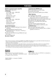
...-in 6-channel power amplifier Minimum RMS output power [ HTR-5750 ] (0.06% THD, 20 Hz - 20 kHz, 8Ω) Front: 90 W + 90 W Center: 90 W Surround: 90 W + 90 W Surround back: 90 W [ HTR-5740 ] (0.06% THD, 20 Hz - 20 kHz, 8Ω) Front: 85 W + 85 W Center: 85 W Surround: 85 W + 85 W Surround back: 85 W Sound field features ◆ Proprietary YAMAHA technology for...
...-in 6-channel power amplifier Minimum RMS output power [ HTR-5750 ] (0.06% THD, 20 Hz - 20 kHz, 8Ω) Front: 90 W + 90 W Center: 90 W Surround: 90 W + 90 W Surround back: 90 W [ HTR-5740 ] (0.06% THD, 20 Hz - 20 kHz, 8Ω) Front: 85 W + 85 W Center: 85 W Surround: 85 W + 85 W Surround back: 85 W Sound field features ◆ Proprietary YAMAHA technology for...
Owners Manual
Page 7
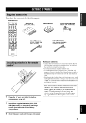
... GETTING STARTED GETTING STARTED Supplied accessories Please check that may have leaked, dispose of them immediately. Remote control CODE SET TRANSMIT POWER TV POWER AV STANDBY CD MD/CD-R TUNER SYSTEM POWER SLEEP DVD DTV/CBL V-AUX MULTI CH IN VCR AMP Batteries (4) (AAA, R03, UM-4) AM loop antenna 75-ohm/300-ohm...
... GETTING STARTED GETTING STARTED Supplied accessories Please check that may have leaked, dispose of them immediately. Remote control CODE SET TRANSMIT POWER TV POWER AV STANDBY CD MD/CD-R TUNER SYSTEM POWER SLEEP DVD DTV/CBL V-AUX MULTI CH IN VCR AMP Batteries (4) (AAA, R03, UM-4) AM loop antenna 75-ohm/300-ohm...
Owners Manual
Page 8
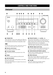
... of all audio channels. Selects the tuning frequency when the colon (:) is in the memory. Note In standby mode, this unit consumes a small amount of power in order to receive infrared-signals from the remote control. 2 Remote control sensor Receives signals from the remote control. 3 Front panel display Shows information about...
... of all audio channels. Selects the tuning frequency when the colon (:) is in the memory. Note In standby mode, this unit consumes a small amount of power in order to receive infrared-signals from the remote control. 2 Remote control sensor Receives signals from the remote control. 3 Front panel display Shows information about...
Owners Manual
Page 10
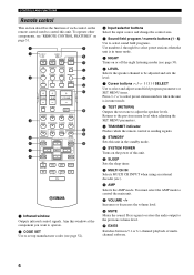
...select the AMP mode to the previous volume level. G EX/ES Switches between 5.1 or 6.1-channel playback of multichannel software. 6 A SYSTEM POWER Turns on or off the night listening modes (see "REMOTE CONTROL FEATURES" on the remote control used to select preset stations when the unit... speaker levels. CONTROLS AND FUNCTIONS Remote control This section describes the function of each control on page 51. 1 2 3 CODE SET TRANSMIT POWER TV POWER AV STANDBY CD MD/CD-R TUNER SYSTEM POWER SLEEP DVD DTV/CBL V-AUX MULTI CH IN VCR AMP TV VOL TV CH VOLUME 9 0 A B C D E 4 5 6 7...
...select the AMP mode to the previous volume level. G EX/ES Switches between 5.1 or 6.1-channel playback of multichannel software. 6 A SYSTEM POWER Turns on or off the night listening modes (see "REMOTE CONTROL FEATURES" on the remote control used to select preset stations when the unit... speaker levels. CONTROLS AND FUNCTIONS Remote control This section describes the function of each control on page 51. 1 2 3 CODE SET TRANSMIT POWER TV POWER AV STANDBY CD MD/CD-R TUNER SYSTEM POWER SLEEP DVD DTV/CBL V-AUX MULTI CH IN VCR AMP TV VOL TV CH VOLUME 9 0 A B C D E 4 5 6 7...

Owners Manual
Page 11
... MEMORY MAN'L/AUTO FM INPUT TUNING MODE AUTO/MAN'L MONO MULTI CH INPUT VOLUME VIDEO AUX VIDEO L AUDIO R 30 30 CODE SET TRANSMIT SYSTEM POWER POWER STANDBY POWER TV AV CD MD/CD-R TUNER SLEEP DVD DTV/CBL V-AUX MULTI CH IN VCR AMP TV VOL TV CH VOLUME TV MUTE TV INPUT...
... MEMORY MAN'L/AUTO FM INPUT TUNING MODE AUTO/MAN'L MONO MULTI CH INPUT VOLUME VIDEO AUX VIDEO L AUDIO R 30 30 CODE SET TRANSMIT SYSTEM POWER POWER STANDBY POWER TV AV CD MD/CD-R TUNER SLEEP DVD DTV/CBL V-AUX MULTI CH IN VCR AMP TV VOL TV CH VOLUME TV MUTE TV INPUT...

Owners Manual
Page 13
S VIDEO jacks are only available for HTR-5750. 4 AC OUTLET(S) Use to supply power to your other A/V components (see page 19). 5 DIGITAL OUTPUT jack (HTR-5750 only) See page 17 for details. 6 Audio component jacks See page 17 for connection information. 7 SUB WOOFER OUTPUT jack See page 12 ...VIDEO MONITOR OUT GND 75Ω UNBAL. SURROUND BACK + AC OUTLETS SWITCHED IMPEDANCE SELECTOR 56 7 8 9 0 1 DIGITAL INPUT jacks [ HTR-5750 ] CD5, DTV/CBL4, DVD3, MD/CD-R2 [ HTR-5740 ] CD3, DTV/CBL2, DVD1 See pages 14, 16 and 17 for details. 2 MULTI CH INPUT jacks See page 15 for ...
S VIDEO jacks are only available for HTR-5750. 4 AC OUTLET(S) Use to supply power to your other A/V components (see page 19). 5 DIGITAL OUTPUT jack (HTR-5750 only) See page 17 for details. 6 Audio component jacks See page 17 for connection information. 7 SUB WOOFER OUTPUT jack See page 12 ...VIDEO MONITOR OUT GND 75Ω UNBAL. SURROUND BACK + AC OUTLETS SWITCHED IMPEDANCE SELECTOR 56 7 8 9 0 1 DIGITAL INPUT jacks [ HTR-5750 ] CD5, DTV/CBL4, DVD3, MD/CD-R2 [ HTR-5740 ] CD3, DTV/CBL2, DVD1 See pages 14, 16 and 17 for details. 2 MULTI CH INPUT jacks See page 15 for ...
Owners Manual
Page 15
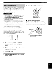
... exception of U.K. PREPARATION SPEAKER SETUP Speaker connections Be sure to 6 ohms before using (see page 20). • Before connecting the speakers, make sure that the power of this type of this unit. If the connections are faulty, no sound will be unnatural and lack bass.
... exception of U.K. PREPARATION SPEAKER SETUP Speaker connections Be sure to 6 ohms before using (see page 20). • Before connecting the speakers, make sure that the power of this type of this unit. If the connections are faulty, no sound will be unnatural and lack bass.
Owners Manual
Page 17
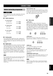
...and analog signals independently. Thus audio signals input to the analog jacks are only output to the analog OUT (REC) jacks. [ HTR-5750 only ] Likewise audio signals input to the digital (OPTICAL or COAXIAL) jacks are only output to achieve high-quality color reproduction. This...to the DIGITAL OUTPUT jack. PREPARATION CONNECTIONS CONNECTIONS Before connecting components CAUTION Do not connect this unit or other components to the mains power until all connections between components are complete. ■ Cable indications For analog signals left jacks. ■ Digital jacks This unit has...
...and analog signals independently. Thus audio signals input to the analog jacks are only output to the analog OUT (REC) jacks. [ HTR-5750 only ] Likewise audio signals input to the digital (OPTICAL or COAXIAL) jacks are only output to achieve high-quality color reproduction. This...to the DIGITAL OUTPUT jack. PREPARATION CONNECTIONS CONNECTIONS Before connecting components CAUTION Do not connect this unit or other components to the mains power until all connections between components are complete. ■ Cable indications For analog signals left jacks. ■ Digital jacks This unit has...

Owners Manual
Page 23
...The memory back-up circuit prevents the stored data from being lost . However if the power cord is disconnected from your other components to any connected component whenever this unit. The maximum power (total power consumption of components) that can be lost even if this unit is controlled by this... 1 OUTLET Korea model None Other models 2 OUTLETS Use these outlets to connect the power cords from the AC wall outlet, or the power supply is turned on. CONNECTIONS English 19 The outlet(s) supply power to this unit is cut for more than one week, the stored data will be...
...The memory back-up circuit prevents the stored data from being lost . However if the power cord is disconnected from your other components to any connected component whenever this unit. The maximum power (total power consumption of components) that can be lost even if this unit is controlled by this... 1 OUTLET Korea model None Other models 2 OUTLETS Use these outlets to connect the power cords from the AC wall outlet, or the power supply is turned on. CONNECTIONS English 19 The outlet(s) supply power to this unit is cut for more than one week, the stored data will be...

Owners Manual
Page 24
...20 If you use one set (A or B), the impedance of each speaker must be fully slid to either position. IMPEDANCE SELECTOR SET BEFORE POWER ON IMPEDANCE SELECTOR switch Switch position Left Right Speaker Front Center, Surround, Surround back Front Center, Surround, Surround back Impedance level If you... Ω or higher. CONNECTIONS ■ IMPEDANCE SELECTOR switch CAUTION Do not change the setting of the IMPEDANCE SELECTOR switch when the unit power is switched on either the front panel or remote control, the IMPEDANCE SELECTOR switch may damage the unit. If this is the case, ...
...20 If you use one set (A or B), the impedance of each speaker must be fully slid to either position. IMPEDANCE SELECTOR SET BEFORE POWER ON IMPEDANCE SELECTOR switch Switch position Left Right Speaker Front Center, Surround, Surround back Front Center, Surround, Surround back Impedance level If you... Ω or higher. CONNECTIONS ■ IMPEDANCE SELECTOR switch CAUTION Do not change the setting of the IMPEDANCE SELECTOR switch when the unit power is switched on either the front panel or remote control, the IMPEDANCE SELECTOR switch may damage the unit. If this is the case, ...

Owners Manual
Page 25
... MEMORY MAN'L/AUTO FM INPUT TUNING MODE AUTO/MAN'L MONO MULTI CH INPUT VIDEO AUX VIDEO L AUDIO R 1 CODE SET TRANSMIT POWER TV POWER AV STANDBY CD MD/CD-R TUNER SYSTEM POWER SLEEP DVD DTV/CBL V-AUX MULTI CH IN VCR AMP 1 TV VOL TV CH VOLUME TV MUTE TV INPUT 1 Press STANDBY.../ON (SYSTEM POWER on the remote control) to this unit. CONNECTIONS English 21 STANDBY /ON SYSTEM POWER or Front panel Remote control 2 Turn on the video monitor connected to turn on the...
... MEMORY MAN'L/AUTO FM INPUT TUNING MODE AUTO/MAN'L MONO MULTI CH INPUT VIDEO AUX VIDEO L AUDIO R 1 CODE SET TRANSMIT POWER TV POWER AV STANDBY CD MD/CD-R TUNER SYSTEM POWER SLEEP DVD DTV/CBL V-AUX MULTI CH IN VCR AMP 1 TV VOL TV CH VOLUME TV MUTE TV INPUT 1 Press STANDBY.../ON (SYSTEM POWER on the remote control) to this unit. CONNECTIONS English 21 STANDBY /ON SYSTEM POWER or Front panel Remote control 2 Turn on the video monitor connected to turn on the...
Owners Manual
Page 26
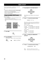
... sizes are defined as follows: [U.S.A. SUBWOOFER YES YES If you have a subwoofer in your headphones from this unit. 1 CODE SET TRANSMIT POWER TV POWER AV STANDBY CD MD/CD-R TUNER SYSTEM POWER SLEEP DVD DTV/CBL V-AUX MULTI CH IN VCR AMP TV VOL TV CH VOLUME TV MUTE TV INPUT 1 2 3 4 MUSIC ENTERTAIN...
... sizes are defined as follows: [U.S.A. SUBWOOFER YES YES If you have a subwoofer in your headphones from this unit. 1 CODE SET TRANSMIT POWER TV POWER AV STANDBY CD MD/CD-R TUNER SYSTEM POWER SLEEP DVD DTV/CBL V-AUX MULTI CH IN VCR AMP TV VOL TV CH VOLUME TV MUTE TV INPUT 1 2 3 4 MUSIC ENTERTAIN...

Owners Manual
Page 28
... CT EON dB 96/24 ft L CR mS dB LFE SL SB SR The unit outputs the test tone from the AC outlet, or the power supply is cut for more than one week, the stored data will be lost even if this unit is in the front panel display. 1 Press... TEST on the remote control. SL-----||----- BASIC SETUP ■ To balance the speaker levels Perform the following steps after balancing the speakers. C-----||----- However, if the power cord is disconnected from the selected speaker and the left front (or left and right speakers. FR-----||-----
... CT EON dB 96/24 ft L CR mS dB LFE SL SB SR The unit outputs the test tone from the AC outlet, or the power supply is cut for more than one week, the stored data will be lost even if this unit is in the front panel display. 1 Press... TEST on the remote control. SL-----||----- BASIC SETUP ■ To balance the speaker levels Perform the following steps after balancing the speakers. C-----||----- However, if the power cord is disconnected from the selected speaker and the left front (or left and right speakers. FR-----||-----

Owners Manual
Page 29
...ROCK 4 MUSIC ENTERTAIN TV THTR 5 6 7 MOVIE 8 q/DTS 9 NIGHT 0 EX/ES 10 PRESET/CH STRAIGHT ENTER EFFECT 7 1 Press STANDBY/ON (SYSTEM POWER on the power. t 96 VCR V-AUX DTV/CBL DVD MD/CD-R TUNER CD 24 MATRIX DISCRETE SILENT CINEMA VIRTUAL q DIGITAL SP A B NIGHT ZONE2 SLEEP 10 D D...volume to this unit. 3 Press SPEAKERS A or B on the video monitor connected to the desired output level. STANDBY /ON SYSTEM POWER or Front panel Remote control 4 Select the input source. PLAYBACK PLAYBACK Basic operations STANDBY /ON PHONES SPEAKERS A B SILENT CINEMA (U.S.A. ...
...ROCK 4 MUSIC ENTERTAIN TV THTR 5 6 7 MOVIE 8 q/DTS 9 NIGHT 0 EX/ES 10 PRESET/CH STRAIGHT ENTER EFFECT 7 1 Press STANDBY/ON (SYSTEM POWER on the power. t 96 VCR V-AUX DTV/CBL DVD MD/CD-R TUNER CD 24 MATRIX DISCRETE SILENT CINEMA VIRTUAL q DIGITAL SP A B NIGHT ZONE2 SLEEP 10 D D...volume to this unit. 3 Press SPEAKERS A or B on the video monitor connected to the desired output level. STANDBY /ON SYSTEM POWER or Front panel Remote control 4 Select the input source. PLAYBACK PLAYBACK Basic operations STANDBY /ON PHONES SPEAKERS A B SILENT CINEMA (U.S.A. ...

Owners Manual
Page 32
... the optimum decoder for multi-channel sources using the DTS-ES decoder. PLAYBACK ■ Remote control operation AMP CODE SET TRANSMIT POWER TV POWER AV STANDBY CD MD/CD-R TUNER SYSTEM POWER SLEEP DVD DTV/CBL V-AUX MULTI CH IN VCR AMP TV VOL TV CH VOLUME TV MUTE TV INPUT TV VOL...
... the optimum decoder for multi-channel sources using the DTS-ES decoder. PLAYBACK ■ Remote control operation AMP CODE SET TRANSMIT POWER TV POWER AV STANDBY CD MD/CD-R TUNER SYSTEM POWER SLEEP DVD DTV/CBL V-AUX MULTI CH IN VCR AMP TV VOL TV CH VOLUME TV MUTE TV INPUT TV VOL...

Owners Manual
Page 33
... Dolby Surround sources. When "SURR LR" (see page 46) or "SURR B" (see page 46). When "2ch Stereo" or "Direct Stereo" is selected. • When the power of discs with 6.1-channel, select a decoder manually (PLIIx Music, EX/ES or EX). • 6.1-channel playback is not possible even if EX/ES is being...
... Dolby Surround sources. When "SURR LR" (see page 46) or "SURR B" (see page 46). When "2ch Stereo" or "Direct Stereo" is selected. • When the power of discs with 6.1-channel, select a decoder manually (PLIIx Music, EX/ES or EX). • 6.1-channel playback is not possible even if EX/ES is being...


