
Owner's Manual
Page 2
...on different branch (circuit breaker or fuse) circuits or install AC line filter/s. Modifications not expressly approved by Yamaha may void your FCC authorization to use of America or its subsidiaries. * This applies only to distribute this product in all installation instructions. Compliance ... Ceci ne s'applique qu'aux produits distribués par Yamaha Canada Musique Ltée. tions does not guarantee that interference will not result in harmful interference with the coloured markings identifying the terminals in your use this type of the following code: GREEN-AND-YELLOW :...
...on different branch (circuit breaker or fuse) circuits or install AC line filter/s. Modifications not expressly approved by Yamaha may void your FCC authorization to use of America or its subsidiaries. * This applies only to distribute this product in all installation instructions. Compliance ... Ceci ne s'applique qu'aux produits distribués par Yamaha Canada Musique Ltée. tions does not guarantee that interference will not result in harmful interference with the coloured markings identifying the terminals in your use this type of the following code: GREEN-AND-YELLOW :...
Owner's Manual
Page 3
...install near water. 6 Clean only with dry cloth. 7 Do not block any way, such as power-supply cord or plug is used, use attachments/accessories specified by the manufacturer. 12 Use only with the cart, stand, tripod, bracket, or table specified by the manufacturer, or sold with one wider than the other apparatus...the power cord from being walked on or pinched particularly at plugs, convenience receptacles, and the point where they exit from the apparatus. 11 Only use caution when moving the cart/apparatus combination to rain or moisture, does not operate normally, or has been dropped.
...install near water. 6 Clean only with dry cloth. 7 Do not block any way, such as power-supply cord or plug is used, use attachments/accessories specified by the manufacturer. 12 Use only with the cart, stand, tripod, bracket, or table specified by the manufacturer, or sold with one wider than the other apparatus...the power cord from being walked on or pinched particularly at plugs, convenience receptacles, and the point where they exit from the apparatus. 11 Only use caution when moving the cart/apparatus combination to rain or moisture, does not operate normally, or has been dropped.
Owner's Manual
Page 4
... ISSUES: Yamaha strives to produce products that are both the letter and the spirit of the law, we want you to be aware of the following: Warning: Do not attempt to recharge, disassemble, or incinerate this manual is properly installed and used in order that you may be...at an end, please observe all batteries away from children. Dispose of used to produce them, meet these parts for graphic symbol markings. Information such as a permanent record of your dealer before requesting service. However, Yamaha reserves the right to change or modify any of the specifications without ...
... ISSUES: Yamaha strives to produce products that are both the letter and the spirit of the law, we want you to be aware of the following: Warning: Do not attempt to recharge, disassemble, or incinerate this manual is properly installed and used in order that you may be...at an end, please observe all batteries away from children. Dispose of used to produce them, meet these parts for graphic symbol markings. Information such as a permanent record of your dealer before requesting service. However, Yamaha reserves the right to change or modify any of the specifications without ...
Owner's Manual
Page 5
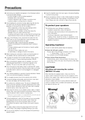
The use of lightning striking in or unplugged with ease. ● Your Yamaha amplifier is a precision musical instrument. If there are attached ... 2: Hot (+), 3: Cold (-) This conforms to the IEC60268 standard. ● About Cellular Phone Interference Cellular phones used in close to an easily accessible electric outlet so it is still connected to the switches and controls. ● ...If the device is to be exposed to liquid dripping or splashing. Attaching and removing the casters (BBT500-115 only) When attaching the supplied casters, make sure that the power on the amplifier and any ...
The use of lightning striking in or unplugged with ease. ● Your Yamaha amplifier is a precision musical instrument. If there are attached ... 2: Hot (+), 3: Cold (-) This conforms to the IEC60268 standard. ● About Cellular Phone Interference Cellular phones used in close to an easily accessible electric outlet so it is still connected to the switches and controls. ● ...If the device is to be exposed to liquid dripping or splashing. Attaching and removing the casters (BBT500-115 only) When attaching the supplied casters, make sure that the power on the amplifier and any ...
Owner's Manual
Page 6
...get the most out of your BBT500-115/BBT500-110 and its 11 sound variation types, 5-band semi-parametric equalizer, compressor, limiter, and noise gate. Thanks to the use in a safe, convenient place for purchasing the Yamaha BBT500-115/BBT500-110 Bass Amplifier. CONTENTS Panel Controls and... Implementation Chart 95 6 The BBT5001-115/BBT500-110 is also equipped with its sophisticated functions, please thoroughly read this Owner's Manual before using two amplifiers to provide bassists with Yamaha's power switching technology, the BBT500-115/BBT500-110 can deliver a maximum 500W of power...
...get the most out of your BBT500-115/BBT500-110 and its 11 sound variation types, 5-band semi-parametric equalizer, compressor, limiter, and noise gate. Thanks to the use in a safe, convenient place for purchasing the Yamaha BBT500-115/BBT500-110 Bass Amplifier. CONTENTS Panel Controls and... Implementation Chart 95 6 The BBT5001-115/BBT500-110 is also equipped with its sophisticated functions, please thoroughly read this Owner's Manual before using two amplifiers to provide bassists with Yamaha's power switching technology, the BBT500-115/BBT500-110 can deliver a maximum 500W of power...
Owner's Manual
Page 7
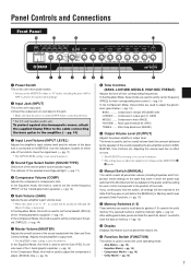
...to memory. (→ pg. 12) !2 Display Displays information such as labeled on the panel, and the setting for each control corresponds to the BBT500. Use the indicators located on tone. * The OUTPUT level setting is not saved in memory. All knobs function as parameter values, etc. !3 Function ... settings. In the Equalizer mode, this knob is set to recall data for their corresponding frequencies. In the Equalizer Mode, this knob is used to set the compressor threshold (THRSLD). (→ pg. 14) u Master Volume (MASTER) Adjusts the overall volume of the eleven preset sound...
...to memory. (→ pg. 12) !2 Display Displays information such as labeled on the panel, and the setting for each control corresponds to the BBT500. Use the indicators located on tone. * The OUTPUT level setting is not saved in memory. All knobs function as parameter values, etc. !3 Function ... settings. In the Equalizer mode, this knob is set to recall data for their corresponding frequencies. In the Equalizer Mode, this knob is used to set the compressor threshold (THRSLD). (→ pg. 14) u Master Volume (MASTER) Adjusts the overall volume of the eleven preset sound...
Owner's Manual
Page 8
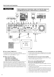
... BLEND control in the Compressor Mode to adjust the balance level between the SEND and RETURN jacks to apply effects to the BBT500's signal. Use the LEVEL control to adjust the volume. !7 Headphones/Line Out Level Control (LEVEL) Adjusts the output level of the PHONES jack and the LINE OUT ... is selected with the level required by the outboard effects processor. Connect this output jack to the INPUT jack on the BBT500 and all other related devices is switched OFF. Use the Level Switch to match the Input/Output level with the @0 Line Out Source Switch at a line level. Both unbalanced ...
... BLEND control in the Compressor Mode to adjust the balance level between the SEND and RETURN jacks to apply effects to the BBT500's signal. Use the LEVEL control to adjust the volume. !7 Headphones/Line Out Level Control (LEVEL) Adjusts the output level of the PHONES jack and the LINE OUT ... is selected with the level required by the outboard effects processor. Connect this output jack to the INPUT jack on the BBT500 and all other related devices is switched OFF. Use the Level Switch to match the Input/Output level with the @0 Line Out Source Switch at a line level. Both unbalanced ...
Owner's Manual
Page 9
... Connector (AC IN) Connect the supplied power cable to this special circuit adds the live characteristics of the circuit should never be loaded into the BBT500's internal memory. (→ pg. 17: MIDI Bulk IN) Panel Controls and Connections @5 Speaker Jacks (SPEAKER 1, 2 (EXT)) Two Speaker ...Limiter Switch (OUTPUT LIMITER: ON/OFF) This switch is connected to produce a distorted sound with one of the following requirements. ● When using both LINE OUT and SPEAKER jack signals. @3 MIDI OUT Jack Connect this setting when connecting to supply the unit with one of the following...
... Connector (AC IN) Connect the supplied power cable to this special circuit adds the live characteristics of the circuit should never be loaded into the BBT500's internal memory. (→ pg. 17: MIDI Bulk IN) Panel Controls and Connections @5 Speaker Jacks (SPEAKER 1, 2 (EXT)) Two Speaker ...Limiter Switch (OUTPUT LIMITER: ON/OFF) This switch is connected to produce a distorted sound with one of the following requirements. ● When using both LINE OUT and SPEAKER jack signals. @3 MIDI OUT Jack Connect this setting when connecting to supply the unit with one of the following...
Owner's Manual
Page 10
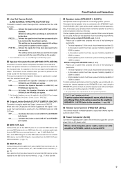
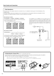
As the BBT500-115's and BBT500-110's two speaker jacks are connected in a parallel circuit inside of the amplifier, adding a 4Ω external speaker to the BBT500 unit as close to the 4Ω internal speaker will change according to the total ... a Series Total impedance = 1st Speaker + 2nd Speaker + 3rd Speaker ... Panel Controls and Connections * Total Impedance Whenever two or more speaker cabinets are used . ● Connected in Parallel Total impedance = Connecting three 4Ω speaker cabinets in a parallel configuration as shown below , results in a total impedance ...
As the BBT500-115's and BBT500-110's two speaker jacks are connected in a parallel circuit inside of the amplifier, adding a 4Ω external speaker to the BBT500 unit as close to the 4Ω internal speaker will change according to the total ... a Series Total impedance = 1st Speaker + 2nd Speaker + 3rd Speaker ... Panel Controls and Connections * Total Impedance Whenever two or more speaker cabinets are used . ● Connected in Parallel Total impedance = Connecting three 4Ω speaker cabinets in a parallel configuration as shown below , results in a total impedance ...
Owner's Manual
Page 11
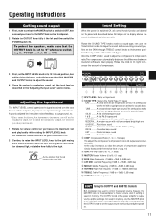
...LEVEL knob. A poorly adjusted level results in noise, feedback, a cutup sound, etc. * Since output levels vary from the bass for use the OUTPUT knob to the right. An ideal level is attained when the green indicator is lit. 2 Continue to rotate the INPUT LEVEL knob... B A fat R & B type sound VINTAGE ..... The OUTPUT knob is the power amplifier's output volume and its setting is not saved in memory. Use the MASTER knob to set individual volume settings of compression. A modern sound with warm mid frequencies MODERN .... Operating Instructions Getting sound output 1 First, make ...
...LEVEL knob. A poorly adjusted level results in noise, feedback, a cutup sound, etc. * Since output levels vary from the bass for use the OUTPUT knob to the right. An ideal level is attained when the green indicator is lit. 2 Continue to rotate the INPUT LEVEL knob... B A fat R & B type sound VINTAGE ..... The OUTPUT knob is the power amplifier's output volume and its setting is not saved in memory. Use the MASTER knob to set individual volume settings of compression. A modern sound with warm mid frequencies MODERN .... Operating Instructions Getting sound output 1 First, make ...
Owner's Manual
Page 12
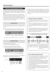
... (1-5) until the knob's position corresponds to pressing a Memory Switch [1]-[5] or the [MANUAL] switch. The value "4.0" flashes on this case, the BBT500 is recalled. * INPUT LEVEL and OUTPUT LEVEL settings are saved to memory. After you recall or store a patch, the value for storing patch data...Patch. For more information on the display but pressed Memory Switch [2] before you want to keep for later use one of the front panel indicators light. Recalling a Patch To use , press and hold the [MANUAL] switch to return the settings to the same condition they were in...
... (1-5) until the knob's position corresponds to pressing a Memory Switch [1]-[5] or the [MANUAL] switch. The value "4.0" flashes on this case, the BBT500 is recalled. * INPUT LEVEL and OUTPUT LEVEL settings are saved to memory. After you recall or store a patch, the value for storing patch data...Patch. For more information on the display but pressed Memory Switch [2] before you want to keep for later use one of the front panel indicators light. Recalling a Patch To use , press and hold the [MANUAL] switch to return the settings to the same condition they were in...
Owner's Manual
Page 13
... on the display when the knob is saved to recall a patch. Enter the Amp Mode using one of the following methods. • The Amp Mode is the default mode when the BBT500's power is used to set the crossover filter, and individual MIDI settings. Detailed Parameter Settings The... BBT500 also features more precise settings for defining the frequencies for each of the Tone Control knobs, ...
... on the display when the knob is saved to recall a patch. Enter the Amp Mode using one of the following methods. • The Amp Mode is the default mode when the BBT500's power is used to set the crossover filter, and individual MIDI settings. Detailed Parameter Settings The... BBT500 also features more precise settings for defining the frequencies for each of the Tone Control knobs, ...
Owner's Manual
Page 14
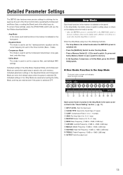
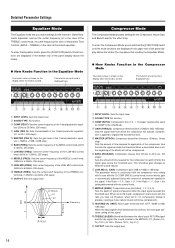
... compressor to switch off the signal. !0 TREBLE (BLEND): Blend level between the effect loop's RETURN signal and the dry signal (the sound created in the BBT500) (0% (Return 0%, Dry 100%) to 100% (Return 100%, Dry 0%)). !1 OUTPUT: Sets the output level 14 To enter the Equalizer mode, press the [FUNCTION] switch. q w e r t y u i...knob. (500Hz to 8.00kHz, 255 steps) !0 TREBLE (FREQ): Sets the center/cutoff frequency of each knob is applied to signals that used by the Equalizer Mode). ● How Knobs Function in the Equalizer Mode The knob's value is shown on the display when the knob...
... compressor to switch off the signal. !0 TREBLE (BLEND): Blend level between the effect loop's RETURN signal and the dry signal (the sound created in the BBT500) (0% (Return 0%, Dry 100%) to 100% (Return 100%, Dry 0%)). !1 OUTPUT: Sets the output level 14 To enter the Equalizer mode, press the [FUNCTION] switch. q w e r t y u i...knob. (500Hz to 8.00kHz, 255 steps) !0 TREBLE (FREQ): Sets the center/cutoff frequency of each knob is applied to signals that used by the Equalizer Mode). ● How Knobs Function in the Equalizer Mode The knob's value is shown on the display when the knob...
Owner's Manual
Page 15
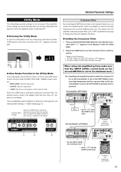
... the INPUT LEVEL, OUTPUT, and COMP knobs function. Other than three seconds (until "utL" appears on the display. Crossover Filter By connecting two BBT500s as shown in the display. First amplifier (HPF 500Hz) INPUT Bass TUNER OUT * Set to "h50" with the COMP control knob Second amplifier ...(LPF or HPF) to its minimum level. These settings are saved internally when you can create a bi-amplified system, where one amplifier is used (when setting the crossover filter), the setting's value is switched OFF. ● Entering the Utility Mode To enter the Utility Mode, from ...
... the INPUT LEVEL, OUTPUT, and COMP knobs function. Other than three seconds (until "utL" appears on the display. Crossover Filter By connecting two BBT500s as shown in the display. First amplifier (HPF 500Hz) INPUT Bass TUNER OUT * Set to "h50" with the COMP control knob Second amplifier ...(LPF or HPF) to its minimum level. These settings are saved internally when you can create a bi-amplified system, where one amplifier is used (when setting the crossover filter), the setting's value is switched OFF. ● Entering the Utility Mode To enter the Utility Mode, from ...
Owner's Manual
Page 16
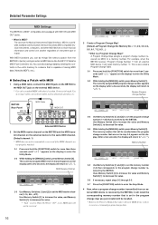
...to a device that is capable of saving MIDI data (Yamaha MDF3, etc.). ● Selecting a Patch with MIDI 1 Using a MIDI cable, connect the MIDI IN jack on the BBT500 to the MIDI OUT jack on the external MIDI device. * Use only a standard MIDI cable that is set , MIDI ... MIDI device on how to receive or transmit program change number transmitted from the BBT500's memory using an external MIDI device like the MFC10 Yamaha MIDI Foot Controller, etc. Use of instrument type or maker. MIDI Receive Channel 2-3 Use Memory Switches [1] and [2] to "utL"). A Program Change Map assigns a...
...to a device that is capable of saving MIDI data (Yamaha MDF3, etc.). ● Selecting a Patch with MIDI 1 Using a MIDI cable, connect the MIDI IN jack on the BBT500 to the MIDI OUT jack on the external MIDI device. * Use only a standard MIDI cable that is set , MIDI ... MIDI device on how to receive or transmit program change number transmitted from the BBT500's memory using an external MIDI device like the MFC10 Yamaha MIDI Foot Controller, etc. Use of instrument type or maker. MIDI Receive Channel 2-3 Use Memory Switches [1] and [2] to "utL"). A Program Change Map assigns a...
Owner's Manual
Page 17
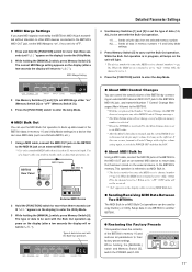
... [MANUAL] switch and Memory Switch [5], switch the POWER switch ON. 17 MIDI Merge Setting 4 Use Memory Switches [1] and [2] to set to 1. Use of a longer cable can result in one BBT500 to another BBT500. ● Restoring the Factory Presets This operation clears the contents of the Number 7 Control Change...utL" appears on the external device, to the BBT500's memory. This operation is referred to as a Yamaha MDF3, etc.). 1 Using a MIDI cable, connect the MIDI OUT jack on the BBT500 to the MIDI IN jack on an external MIDI device. * Use only a standard MIDI cable that has been ...
... [MANUAL] switch and Memory Switch [5], switch the POWER switch ON. 17 MIDI Merge Setting 4 Use Memory Switches [1] and [2] to set to 1. Use of a longer cable can result in one BBT500 to another BBT500. ● Restoring the Factory Presets This operation clears the contents of the Number 7 Control Change...utL" appears on the external device, to the BBT500's memory. This operation is referred to as a Yamaha MDF3, etc.). 1 Using a MIDI cable, connect the MIDI OUT jack on the BBT500 to the MIDI IN jack on an external MIDI device. * Use only a standard MIDI cable that has been ...
Owner's Manual
Page 19
...Jack TUNER OUT: Standard Monaural Phone Jack MIDI IN, MIDI OUT: 5-pin DIN jack Speaker Section Speaker Power Handling Impedance BBT500-115 : 15" Woofer x1, Tweeter x1 BBT500-110 : 10" Woofer x1, Tweeter x1 250 Wrms 4 Ω A/D Conversion 24 bit D/A Conversion 24 bit Sampling ... 23.9 kg (52 lbs. 11 oz) General model : 24.4 kg (53 lbs. 13 oz) BBT500-110 U.S. Specifications Power Amplifier Section Class-D power amplifier circuitry Output 250 W/4Ω (When used alone) 500 W/2Ω (Max output with external speaker connected) Preamplifier Section All digital signal processing Sound Type...
...Jack TUNER OUT: Standard Monaural Phone Jack MIDI IN, MIDI OUT: 5-pin DIN jack Speaker Section Speaker Power Handling Impedance BBT500-115 : 15" Woofer x1, Tweeter x1 BBT500-110 : 10" Woofer x1, Tweeter x1 250 Wrms 4 Ω A/D Conversion 24 bit D/A Conversion 24 bit Sampling ... 23.9 kg (52 lbs. 11 oz) General model : 24.4 kg (53 lbs. 13 oz) BBT500-110 U.S. Specifications Power Amplifier Section Class-D power amplifier circuitry Output 250 W/4Ω (When used alone) 500 W/2Ω (Max output with external speaker connected) Preamplifier Section All digital signal processing Sound Type...
