Service Manual
Page 1
XL795D Service Manual
XL795D Service Manual
Service Manual
Page 2
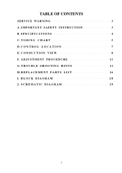
T I M I O N S 4 C. S P E C I F I C A T I N G C H A R T 5 D. ADJUSTMENT PROCEDURE 11 G. R E P L A C E M E N T P A R T S L I S T 16 I O N 7 E. C O N T R O L L O C A T I . C O N D U C T I O N V I N T S 12 H. T R O U B L E S H O O T I N G H I E W 8 F. TABLE OF CONTENTS SERVICE WARNING 3 A. S C H E M A T I C D I O N 3 B. I M P O R T A N T S A F E T Y I N S T R U C T I A G R A M 29 B L O C K D I A G R A M 28 J.
T I M I O N S 4 C. S P E C I F I C A T I N G C H A R T 5 D. ADJUSTMENT PROCEDURE 11 G. R E P L A C E M E N T P A R T S L I S T 16 I O N 7 E. C O N T R O L L O C A T I . C O N D U C T I O N V I N T S 12 H. T R O U B L E S H O O T I N G H I E W 8 F. TABLE OF CONTENTS SERVICE WARNING 3 A. S C H E M A T I C D I O N 3 B. I M P O R T A N T S A F E T Y I N S T R U C T I A G R A M 29 B L O C K D I A G R A M 28 J.
Service Manual
Page 3
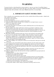
... your electrician to replace your dealer or local power company 9. Unplug this service manual,please ensure that are covered by the operating instructions since improper adjustment of other risks.Refer all of these instructions. 3. Slots and openings in the user's manual for service. f. Follow all the procedures outlined in the cabinet and the back or bottom are provided for cleaning. 5. If the product...
... your electrician to replace your dealer or local power company 9. Unplug this service manual,please ensure that are covered by the operating instructions since improper adjustment of other risks.Refer all of these instructions. 3. Slots and openings in the user's manual for service. f. Follow all the procedures outlined in the cabinet and the back or bottom are provided for cleaning. 5. If the product...
Service Manual
Page 4
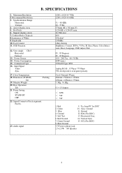
SPECIFICATIONS 1. Support display colors 7. Power Saving ON STAND BY OFF Packing 22. Signal Connector Pin Assignment Pin No. 23. Blue 11. Green Ground 15. Synchronization Range Horizontal Vertical 4. Dot Pitch 6. User Control 11. Base Operation Tilt 21. Red 9. Recommend Resolution 3. Power Consumption 15. Color Temperature 18. Size, Phase, Color Select, Auto, Reset, Language, OSD Adjust, Exit 85 , 85 Degrees 85 , 85 Degrees 100 - 240 Vac 60 / 50 Hz 60W (max.) 15 Pin D Type / DVI Analog R.G.B. , 0.7Vp-p / 75 Ohms TTL level,positive or negative...
SPECIFICATIONS 1. Support display colors 7. Power Saving ON STAND BY OFF Packing 22. Signal Connector Pin Assignment Pin No. 23. Blue 11. Green Ground 15. Synchronization Range Horizontal Vertical 4. Dot Pitch 6. User Control 11. Base Operation Tilt 21. Red 9. Recommend Resolution 3. Power Consumption 15. Color Temperature 18. Size, Phase, Color Select, Auto, Reset, Language, OSD Adjust, Exit 85 , 85 Degrees 85 , 85 Degrees 100 - 240 Vac 60 / 50 Hz 60W (max.) 15 Pin D Type / DVI Analog R.G.B. , 0.7Vp-p / 75 Ohms TTL level,positive or negative...
Service Manual
Page 6
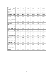
Modes Preset VESA 800X600 Pixel clock (MHz) 49.500 H-Frequency (KHz) 46.875 VESA 1024X768 65.000 VESA 1024X768 75.000 VESA VESA VESA 1024X768 1280X1024 1280X1024 78.750 108.00 135.00 48.363 56.476 60.023 63.981 79.976 H-Total (µs) 21.333 20.677 17.707 16.660 15.630 12.540 H-Active Display (µs) H-Blanking...
Modes Preset VESA 800X600 Pixel clock (MHz) 49.500 H-Frequency (KHz) 46.875 VESA 1024X768 65.000 VESA 1024X768 75.000 VESA VESA VESA 1024X768 1280X1024 1280X1024 78.750 108.00 135.00 48.363 56.476 60.023 63.981 79.976 H-Total (µs) 21.333 20.677 17.707 16.660 15.630 12.540 H-Active Display (µs) H-Blanking...
Service Manual
Page 7
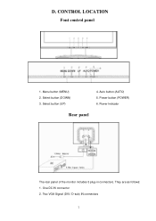
Menu button (MENU) 2. Power button (POWER) 6. Power Indicator Rear panel The rear panel of the monitor includes 3 plug-in connectors. Select button (DOWN) 3. Two VGA Signal (DVI / D-sub) IN connectors They are as follows: 1. Auto button (AUTO) 5. CONTROL LOCATION Font control panel 1. D. One DC IN connector 2. Select button (UP) 4.
Menu button (MENU) 2. Power button (POWER) 6. Power Indicator Rear panel The rear panel of the monitor includes 3 plug-in connectors. Select button (DOWN) 3. Two VGA Signal (DVI / D-sub) IN connectors They are as follows: 1. Auto button (AUTO) 5. CONTROL LOCATION Font control panel 1. D. One DC IN connector 2. Select button (UP) 4.
Service Manual
Page 11
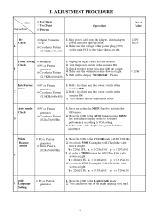
.... Plug power cable into the monitor. 2. Hold ‹ key,then turn the power switch of the monitor OFF. 2. Y = 220±0.1FL x = 0.299±0.01 y = 0.315±0.01 4. Y = 220±0.1FL x = 0.313±0.01 y = 0.329±0.01 OSD F Language Setting PC or Pattern generator 1. Move the OSD to the COLOR mode (AUTO COLOR). 2. Unplug the signal cable into the adapter, check adapter power indicator light up orange. 4. Check monitor power indicator light up green. 2. Move the OSD to the LANGUAGE mode. 2. Move...
.... Plug power cable into the monitor. 2. Hold ‹ key,then turn the power switch of the monitor OFF. 2. Y = 220±0.1FL x = 0.299±0.01 y = 0.315±0.01 4. Y = 220±0.1FL x = 0.313±0.01 y = 0.329±0.01 OSD F Language Setting PC or Pattern generator 1. Move the OSD to the COLOR mode (AUTO COLOR). 2. Unplug the signal cable into the adapter, check adapter power indicator light up orange. 4. Check monitor power indicator light up green. 2. Move the OSD to the LANGUAGE mode. 2. Move...
Service Manual
Page 12
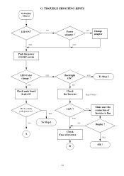
TROUBLE SHOOTING HINTS LED ON ? NO Check the Inverter YES To Step 2 High Voltage ! NO Check main board Scaler IC Back light ON? NO YES Push the power ON/OFF switch Power adapter ? YES NO Change adapter LED Color YES change ? NO A YES To Step 2 +12V ? YES OK ! Hi / Lo under push power sw? NO YES NO Check Fuse of inverter B Make sure the connection of Inverter is fine Display ? No Display ( Black ) G.
TROUBLE SHOOTING HINTS LED ON ? NO Check the Inverter YES To Step 2 High Voltage ! NO Check main board Scaler IC Back light ON? NO YES Push the power ON/OFF switch Power adapter ? YES NO Change adapter LED Color YES change ? NO A YES To Step 2 +12V ? YES OK ! Hi / Lo under push power sw? NO YES NO Check Fuse of inverter B Make sure the connection of Inverter is fine Display ? No Display ( Black ) G.

Service Manual
Page 13
B Hi / Lo under push power sw? A Check the connection of control board Display ? NO Change the main board YES OK ! NO To Step 2 YES OK ! YES Change the Inverter NO Change the main board Display ?
B Hi / Lo under push power sw? A Check the connection of control board Display ? NO Change the main board YES OK ! NO To Step 2 YES OK ! YES Change the Inverter NO Change the main board Display ?

Service Manual
Page 14
NO Repair 5V Circuit YES Repair DPMS Circuit YES Change Scaler IC NO Check H/V Signal Display ? YES OK ! Step 2 Check the main board 12V ? YES Check the main board DPMS Circuit ? NO Change Signal Cable NO Check Fuse, Adapter YES +5.0 V ? YES H/V input Signal ?
NO Repair 5V Circuit YES Repair DPMS Circuit YES Change Scaler IC NO Check H/V Signal Display ? YES OK ! Step 2 Check the main board 12V ? YES Check the main board DPMS Circuit ? NO Change Signal Cable NO Check Fuse, Adapter YES +5.0 V ? YES H/V input Signal ?

Service Manual
Page 15
YES OK ! NO Check H/V Signal NO Check 3.3V Regulator NO Repair 3.3V Circuit YES Change Scaler IC Display ? YES Check the main board 3.3V Regulator ? YES H/V Input Signal ? Repair 5V Circuit YES +3.3V ? NO Change Signal Cable No display (White) Check the main NO board 5V ?
YES OK ! NO Check H/V Signal NO Check 3.3V Regulator NO Repair 3.3V Circuit YES Change Scaler IC Display ? YES Check the main board 3.3V Regulator ? YES H/V Input Signal ? Repair 5V Circuit YES +3.3V ? NO Change Signal Cable No display (White) Check the main NO board 5V ?
Service Manual
Page 16
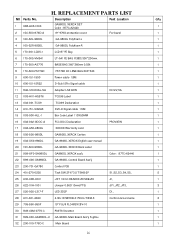
...-151-19R2A5 DVI-D Signal cable 1.5M 15 003-000-ALL-1 Bar Code Label 110X50MM 16 002-002-0DOC-A FCC DOC Declaration PROVIEW 17 002-G50-980DL XEROX Warranty card 18 005-500-980DL GA980DL XEROX Carton 19 002-U50-980DL GA-980DL XEROX English user manual 20 153-500-980DL GA-980DL XEROX Back Label 21 999-XF0-GA980DL GA980DL XEROX ass'y Color : 877C...
...-151-19R2A5 DVI-D Signal cable 1.5M 15 003-000-ALL-1 Bar Code Label 110X50MM 16 002-002-0DOC-A FCC DOC Declaration PROVIEW 17 002-G50-980DL XEROX Warranty card 18 005-500-980DL GA980DL XEROX Carton 19 002-U50-980DL GA-980DL XEROX English user manual 20 153-500-980DL GA-980DL XEROX Back Label 21 999-XF0-GA980DL GA980DL XEROX ass'y Color : 877C...

Service Manual
Page 18
... 75 506-1LM-3485 LM3485/NS MSOP-8 76 506-524-LC21 Memory IC 24LC21 SMD 77 506-5EN-29LV8 Flash 8M EN29LV800T-70RTC/EON 78 506-5NM-24C16 Linear OC NM24C16M-8 (SMD) 79 506-774-LCX14 SMD Hi ...90 558-352-5000 SMD Fuse 1206 24V 5A 91 630-006-1008 Base 6P JWT A2001 Pitch 2 92 630-008-C001 JST 1.5mm HEADER ZR S8B-ZR Part Location C22., C23., C24.,C25.,C27., C5.,C193.,C194.,C1.,C4.,... 0603 69 409-003-0110 DC Jack 3.5D SCD510 70 483-002-104S6 Connector Pin Pitch 2.54mm 1*4 Pin 71 485-415-S070 D-SUB 3R15 180D H6.8 Blue 72 485-D25-S118 DVI-D connector 11.40mm 73 506-0AI-C1084 SMD REG.
... 75 506-1LM-3485 LM3485/NS MSOP-8 76 506-524-LC21 Memory IC 24LC21 SMD 77 506-5EN-29LV8 Flash 8M EN29LV800T-70RTC/EON 78 506-5NM-24C16 Linear OC NM24C16M-8 (SMD) 79 506-774-LCX14 SMD Hi ...90 558-352-5000 SMD Fuse 1206 24V 5A 91 630-006-1008 Base 6P JWT A2001 Pitch 2 92 630-008-C001 JST 1.5mm HEADER ZR S8B-ZR Part Location C22., C23., C24.,C25.,C27., C5.,C193.,C194.,C1.,C4.,... 0603 69 409-003-0110 DC Jack 3.5D SCD510 70 483-002-104S6 Connector Pin Pitch 2.54mm 1*4 Pin 71 485-415-S070 D-SUB 3R15 180D H6.8 Blue 72 485-D25-S118 DVI-D connector 11.40mm 73 506-0AI-C1084 SMD REG.
Service Manual
Page 20
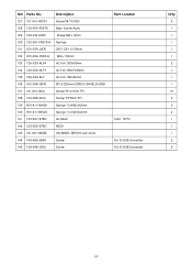
NO Parts No. 127 101-010-4033-1 128 132-300-PS576 129 106-012-6033 130 132-001-PS576-A 131 631-030-J976 132 631-006-7008-A ... ISO Base Screw Ass'y Screw M6 L 12mm Springe 30P 1.25-1.0 130mm Wire 150mm AL Foil 200x30mm AL Foil W30*L90mm AL Foil 150x30mm 8P1.5 220mm+CORE SHIELD+GND Screw P3*L10mm TP1 Screw T3*8mm TP1 Sponge 11x405.2x2mm Sponge 11x323.5x2mm AL Neck NECK GA-980DL XEROX rear cover Screw Screw Part Location Color : 877C For D-SUB Connector For D-SUB Connector Q'ty...
NO Parts No. 127 101-010-4033-1 128 132-300-PS576 129 106-012-6033 130 132-001-PS576-A 131 631-030-J976 132 631-006-7008-A ... ISO Base Screw Ass'y Screw M6 L 12mm Springe 30P 1.25-1.0 130mm Wire 150mm AL Foil 200x30mm AL Foil W30*L90mm AL Foil 150x30mm 8P1.5 220mm+CORE SHIELD+GND Screw P3*L10mm TP1 Screw T3*8mm TP1 Sponge 11x405.2x2mm Sponge 11x323.5x2mm AL Neck NECK GA-980DL XEROX rear cover Screw Screw Part Location Color : 877C For D-SUB Connector For D-SUB Connector Q'ty...
Service Manual
Page 29
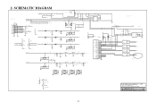
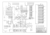
... VGA_HSYNC 2 7 8 6 7 8 8 6 8 99 27 36 5 5 4 4 TP 99 36 5 5 4 4 TP 99 18 27 36 5 5 4 4 TP 99 18 36 5 5 4 4 TP A C 4/18 Add. SCHEMATIC DIAGRAM 17 4/18 Add. CN14 D4 DAN202K/NC A1 A2 VCC 4/18 change PIN4 VE C AC AC D2 DAN217K(NP) C A2 D1 DAN202K/NC C R1 R3 R4 47K 47K A1 47 R6 47.../5_SHLD DATA5DATA5+ 16 17 18 19 20 21 22 CLK_SHLD 23 CLK+ 24 CLK- J. Tel: 886-2-2231-6789 Fax: 886-2-2232-4613 Title VGA & DVI INPUT Size Document Number Rev 200-100-776D-D (PV7-S1) A Date: Thursday, September 18, 2003 Sheet 1 of 6
... VGA_HSYNC 2 7 8 6 7 8 8 6 8 99 27 36 5 5 4 4 TP 99 36 5 5 4 4 TP 99 18 27 36 5 5 4 4 TP 99 18 36 5 5 4 4 TP A C 4/18 Add. SCHEMATIC DIAGRAM 17 4/18 Add. CN14 D4 DAN202K/NC A1 A2 VCC 4/18 change PIN4 VE C AC AC D2 DAN217K(NP) C A2 D1 DAN202K/NC C R1 R3 R4 47K 47K A1 47 R6 47.../5_SHLD DATA5DATA5+ 16 17 18 19 20 21 22 CLK_SHLD 23 CLK+ 24 CLK- J. Tel: 886-2-2231-6789 Fax: 886-2-2232-4613 Title VGA & DVI INPUT Size Document Number Rev 200-100-776D-D (PV7-S1) A Date: Thursday, September 18, 2003 Sheet 1 of 6
Service Manual
Page 30
... FILTER 37 RED 43 GREEN 44 SOG 50 BLUE 64 VS 65 H S 7 8 RX2P RX2M 10 11 RX1P RX1M 13 PW13x 14 RX0P RX0M 16 U4A 17 R C P Graphics and RCM Video Port 5 RTERM ...3 SDA SCL 3 BUZZER XCLK 33 R611 4 LVDSON DS3 33 R612 6 VOLUME 5 PWMOUT Add Pin206 Buzzer 208 207 206 205 204 203 202 201 142 ... DG4 DG5 DG6 DG7 88 87 86 85 82 81 80 79 Display Port DB0 DB1 DB2 78 77 74 73 DB3 71 DB4 70 DB5...2232-4613 Title PW13XA (A/D+Scaler) Size Document Number Rev 200-100-776D-D (PV7-S2) A Date: Thursday, September 18, 2003 Sheet 2 of 6 Sleep Mode 35ma 40ma max. LV1 DPV1 ...
... FILTER 37 RED 43 GREEN 44 SOG 50 BLUE 64 VS 65 H S 7 8 RX2P RX2M 10 11 RX1P RX1M 13 PW13x 14 RX0P RX0M 16 U4A 17 R C P Graphics and RCM Video Port 5 RTERM ...3 SDA SCL 3 BUZZER XCLK 33 R611 4 LVDSON DS3 33 R612 6 VOLUME 5 PWMOUT Add Pin206 Buzzer 208 207 206 205 204 203 202 201 142 ... DG4 DG5 DG6 DG7 88 87 86 85 82 81 80 79 Display Port DB0 DB1 DB2 78 77 74 73 DB3 71 DB4 70 DB5...2232-4613 Title PW13XA (A/D+Scaler) Size Document Number Rev 200-100-776D-D (PV7-S2) A Date: Thursday, September 18, 2003 Sheet 2 of 6 Sleep Mode 35ma 40ma max. LV1 DPV1 ...
Service Manual
Page 31
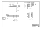
... 8 9 10 11 12 13 14 15 16 17 18 19 20 21 22 23 24 25 26 27 28 29 30 CON30 OPTIONAL Promjet Header, Removed for Production Proview Electronics (Taiwan) Co., LTD. 6F, NO.1, Pau-Sheng Rd., Yung-Ho City, Taipei County, Taiwan R.O.C. 2 LED2 2 RDn...LED_G C Q2 E 2N3904 Modify 8-pin connector WAFE-8PIN-1.5MM-90@ CN1 1 2 3 4 5 6 7 8 9 10 V33 1.POWER 2.LED G 3.LED O 4.DOWN5.UP+ 6.MENU 7.AUTO 8.GND 9.V33 10.BUZZER PROVIEW KEY PAD --OK BUZZER 2 4/18 Add. Tel: 886-2-2231-6789 Fax: 886-2-2232-4613 Title MEMORY & LCD POWER CONTROL Size Document Number Rev 200-100-776D-D (PV7-S2)...
... 8 9 10 11 12 13 14 15 16 17 18 19 20 21 22 23 24 25 26 27 28 29 30 CON30 OPTIONAL Promjet Header, Removed for Production Proview Electronics (Taiwan) Co., LTD. 6F, NO.1, Pau-Sheng Rd., Yung-Ho City, Taipei County, Taiwan R.O.C. 2 LED2 2 RDn...LED_G C Q2 E 2N3904 Modify 8-pin connector WAFE-8PIN-1.5MM-90@ CN1 1 2 3 4 5 6 7 8 9 10 V33 1.POWER 2.LED G 3.LED O 4.DOWN5.UP+ 6.MENU 7.AUTO 8.GND 9.V33 10.BUZZER PROVIEW KEY PAD --OK BUZZER 2 4/18 Add. Tel: 886-2-2231-6789 Fax: 886-2-2232-4613 Title MEMORY & LCD POWER CONTROL Size Document Number Rev 200-100-776D-D (PV7-S2)...
Service Manual
Page 33
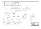
... Choose one package V12 L25 BEAD_80R L25A BEAD_80R(NC) S2 2 1 NC C99 0.01uF GND VIN1 C100 0.1uF GND L26 BE1206 C101 220uF/16V 4/18 C14 change into C10 GND C D12 MMSZ5248B(NC) C102 C103 R84 C10 75K 103 0.1uF 0.01uF U13 8 7 VIN ISENSE 1 2 6 PGATE GND 3 5 PWR_GND NC ADJ FB 4 LM3485 A ... 2 Proview Electronics (Taiwan) Co., LTD. 6F, NO.1, Pau-Sheng Rd., Yung-Ho City, Taipei County, Taiwan R.O.C. Tel: 886-2-2231-6789 Fax: 886-2-2232-4613 Title POWER SUPPLY Size Document Number Rev 200-100-776D-D (PV7-S2) A Date: Thursday, September 18, 2003 Sheet 5 of 6
... Choose one package V12 L25 BEAD_80R L25A BEAD_80R(NC) S2 2 1 NC C99 0.01uF GND VIN1 C100 0.1uF GND L26 BE1206 C101 220uF/16V 4/18 C14 change into C10 GND C D12 MMSZ5248B(NC) C102 C103 R84 C10 75K 103 0.1uF 0.01uF U13 8 7 VIN ISENSE 1 2 6 PGATE GND 3 5 PWR_GND NC ADJ FB 4 LM3485 A ... 2 Proview Electronics (Taiwan) Co., LTD. 6F, NO.1, Pau-Sheng Rd., Yung-Ho City, Taipei County, Taiwan R.O.C. Tel: 886-2-2231-6789 Fax: 886-2-2232-4613 Title POWER SUPPLY Size Document Number Rev 200-100-776D-D (PV7-S2) A Date: Thursday, September 18, 2003 Sheet 5 of 6

Service Manual
Page 34
...NC) R119 10K(NC) GND GND R127 VOLUME 2 22 LM4838 1 C158 0.1uF C159 10UFA/u1d6iVo GND 2 Audio GND R122 20K R123 33K C162 33PF R120 20K C150 0.068uF MUTE MODE GAIN SDWN HPS 01 1 00 L42 0R 1 2 GND Audio GND 3/18 change GND Proview Electronics (Taiwan) Co., LTD....BASE2S 1 2 CN6 DEL C134 DEL R86 DEL R89 L-OUT 2 MUTE Audio GND AUD4835_SD VCC R117 10K AUD4835_DCVOL 2 Shutdown 3 Gain Select 7 DC_Vol 26 Right_outm Right Out- Tel: 886-2-2231-6789 Fax: 886-2-2232-4613 Title AUDIO Size Document Number Rev 200-100-776D-D (PV7-S2) A Date: Thursday, September ...
...NC) R119 10K(NC) GND GND R127 VOLUME 2 22 LM4838 1 C158 0.1uF C159 10UFA/u1d6iVo GND 2 Audio GND R122 20K R123 33K C162 33PF R120 20K C150 0.068uF MUTE MODE GAIN SDWN HPS 01 1 00 L42 0R 1 2 GND Audio GND 3/18 change GND Proview Electronics (Taiwan) Co., LTD....BASE2S 1 2 CN6 DEL C134 DEL R86 DEL R89 L-OUT 2 MUTE Audio GND AUD4835_SD VCC R117 10K AUD4835_DCVOL 2 Shutdown 3 Gain Select 7 DC_Vol 26 Right_outm Right Out- Tel: 886-2-2231-6789 Fax: 886-2-2232-4613 Title AUDIO Size Document Number Rev 200-100-776D-D (PV7-S2) A Date: Thursday, September ...

