Quick Reference Guide
Page 6
... Troubleshooting 29 Fault History Log 29 Power on self-diagnostic test 30 Print engine troubleshooting 31 Testing the print engine controller board 31 Verifying printer operation by using its self-test print 32 Verifying power supply operation 32 Measuring power supply voltages 32 Inspecting the low... 39 The paper tray indicates it is empty when it is not 39 Service Guide v Contents General Information 1 The Phaser 2135 Color Printer 2 Printer RAM and printer capabilities 4 CRC life counter behavior 4 Print engine assemblies 5 The image processor board 8 The control panel 9 On Line LED 9 !
... Troubleshooting 29 Fault History Log 29 Power on self-diagnostic test 30 Print engine troubleshooting 31 Testing the print engine controller board 31 Verifying printer operation by using its self-test print 32 Verifying power supply operation 32 Measuring power supply voltages 32 Inspecting the low... 39 The paper tray indicates it is empty when it is not 39 Service Guide v Contents General Information 1 The Phaser 2135 Color Printer 2 Printer RAM and printer capabilities 4 CRC life counter behavior 4 Print engine assemblies 5 The image processor board 8 The control panel 9 On Line LED 9 !

Quick Reference Guide
Page 9
... 114 Control panel 115 Paper feed components 116 Tray 1 feed roller and nudger roller 116 Paper-size sensing board 117 Main feeder assembly 118 Paper tray lift motor 118 Multi-sheet bypass feeder components 119 Multi-sheet bypass ...feeder 119 Drive gear 119 Multi-sheet bypass feeder sensors 119 Temperature/humidity sensor board 119 Paper transport components 121 Tray 1 entrance sensor actuator 121 Belt entrance and multi-sheet bypass feed sensor ... roller 135 Exit sensor assembly 137 Eject guide assembly 138 Stack full sensor 139 viii Phaser 2135 Color Printer
... 114 Control panel 115 Paper feed components 116 Tray 1 feed roller and nudger roller 116 Paper-size sensing board 117 Main feeder assembly 118 Paper tray lift motor 118 Multi-sheet bypass feeder components 119 Multi-sheet bypass ...feeder 119 Drive gear 119 Multi-sheet bypass feeder sensors 119 Temperature/humidity sensor board 119 Paper transport components 121 Tray 1 entrance sensor actuator 121 Belt entrance and multi-sheet bypass feed sensor ... roller 135 Exit sensor assembly 137 Eject guide assembly 138 Stack full sensor 139 viii Phaser 2135 Color Printer

Quick Reference Guide
Page 11
Figures The Phaser 2135 Color Printer with lower tray assembly and lower tray deck 1 Print engine circuit boards 5 Print engine sensor and switch locations 6 Print engine motors, clutches and solenoids 7 Features of the controller board 8 The control panel 9 The printer rear panel 10 Tray switch sensors and actuators 12 Door safety interlock switches 35 Print problem caused...
Figures The Phaser 2135 Color Printer with lower tray assembly and lower tray deck 1 Print engine circuit boards 5 Print engine sensor and switch locations 6 Print engine motors, clutches and solenoids 7 Features of the controller board 8 The control panel 9 The printer rear panel 10 Tray switch sensors and actuators 12 Door safety interlock switches 35 Print problem caused...

Quick Reference Guide
Page 12
... 142 Removing the fuser motor and transfer belt drive motor assembly 143 Removing the shutter plate 144 Removing the color registration sensor assembly 145 Removing the color registration solenoid 146 Removing an LED assembly 147 Removing the drum contact assembly 148 Removing the toner sensor actuators ... Top cover FRUs 157 Printer chassis FRUs (1 of 2) 159 Printer chassis FRUs (2 of 2) 161 Paper tray and paper tray guides FRUs 163 Electrical components FRUs 164 Duplexer unit 165 Lower Tray Assembly FRUs 167 Wiring diagram 177 Wire routing at the engine controller board 178 Details of wiring...
... 142 Removing the fuser motor and transfer belt drive motor assembly 143 Removing the shutter plate 144 Removing the color registration sensor assembly 145 Removing the color registration solenoid 146 Removing an LED assembly 147 Removing the drum contact assembly 148 Removing the toner sensor actuators ... Top cover FRUs 157 Printer chassis FRUs (1 of 2) 159 Printer chassis FRUs (2 of 2) 161 Paper tray and paper tray guides FRUs 163 Electrical components FRUs 164 Duplexer unit 165 Lower Tray Assembly FRUs 167 Wiring diagram 177 Wire routing at the engine controller board 178 Details of wiring...
Quick Reference Guide
Page 13
...and top cover 154 FRU part list of the top cover inner frame 156 FRU part list of the printer chassis (1 of 2) 158 FRU of the printer chassis (2 of 2) 160 FRU of the paper tray and paper tray guides 162 Electrical components FRUs 164...accessories 170 xii Phaser 2135 Color Printer Tables Entering special operating modes 11 Paper size detection 12 Physical dimensions 13 Printer clearances 13 Functional specifications 14 Electrical specifications 15 Environmental specifications 15 Printer fault messages 17 System controller board diagnostic error codes 27 System controller board fatal error codes...
...and top cover 154 FRU part list of the top cover inner frame 156 FRU part list of the printer chassis (1 of 2) 158 FRU of the printer chassis (2 of 2) 160 FRU of the paper tray and paper tray guides 162 Electrical components FRUs 164...accessories 170 xii Phaser 2135 Color Printer Tables Entering special operating modes 11 Paper size detection 12 Physical dimensions 13 Printer clearances 13 Functional specifications 14 Electrical specifications 15 Environmental specifications 15 Printer fault messages 17 System controller board diagnostic error codes 27 System controller board fatal error codes...

Quick Reference Guide
Page 15
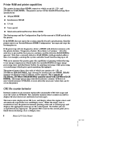
...color PCL5C printer language. and 256-Mbyte RAM DIMMs can be added with an EFI image processing controller board supporting Adobe's PostScript Level 3 page description language. The resolution supported is 512 Mbytes. The auto-duplexer unit (optional on paper sizes such as standard mode. The printer support printing on the Phaser 2135N) allows the printer...-sheet bypass feeder from an adjustable tray. The printer is always 6.5 ppm. The Phaser 2135N prints at 600 x 600 dpi. The printer also features a built-in color, the printer prints at 26 ppm on the chosen resolution and...
...color PCL5C printer language. and 256-Mbyte RAM DIMMs can be added with an EFI image processing controller board supporting Adobe's PostScript Level 3 page description language. The resolution supported is 512 Mbytes. The auto-duplexer unit (optional on paper sizes such as standard mode. The printer support printing on the Phaser 2135N) allows the printer...-sheet bypass feeder from an adjustable tray. The printer is always 6.5 ppm. The Phaser 2135N prints at 600 x 600 dpi. The printer also features a built-in color, the printer prints at 26 ppm on the chosen resolution and...
Quick Reference Guide
Page 17
...of RAM installed in order to finish before declaring a Low or Empty state. 4 Phaser 2135 Color Printer If the DIMM does not meets the system controller board's specifications, then the printer reports an "Invalid Memory DIMM Configuration" message and stops the booting process. If ...the power-up at all for toner, the printer terminates printing at the end of ...
...of RAM installed in order to finish before declaring a Low or Empty state. 4 Phaser 2135 Color Printer If the DIMM does not meets the system controller board's specifications, then the printer reports an "Invalid Memory DIMM Configuration" message and stops the booting process. If ...the power-up at all for toner, the printer terminates printing at the end of ...
Quick Reference Guide
Page 19
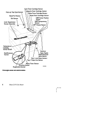
Cyan Toner Cartridge Sensor Face-up Tray Open Sensor Magenta Toner Cartridge Sensor Yellow Toner Cartridge Sensor Stack Full Sensor Black Toner Cartridge Sensor Exit Sensor Color Registration Sensor Assembly MBF Home Position Sensor MBFTransparency Sensor MPT Empty Sensor Temperature/ Humidity Sensor Board Belt Entrance Sensor Top Door Open Switch Right-side Door Open Switch Tray 1 Low Paper Sensor Tray 1 Paper Out Sensor Waste Toner Sensor Entrance Sensor Registration Sensor 0725-63 Print engine sensor and switch locations 6 Phaser 2135 Color Printer
Cyan Toner Cartridge Sensor Face-up Tray Open Sensor Magenta Toner Cartridge Sensor Yellow Toner Cartridge Sensor Stack Full Sensor Black Toner Cartridge Sensor Exit Sensor Color Registration Sensor Assembly MBF Home Position Sensor MBFTransparency Sensor MPT Empty Sensor Temperature/ Humidity Sensor Board Belt Entrance Sensor Top Door Open Switch Right-side Door Open Switch Tray 1 Low Paper Sensor Tray 1 Paper Out Sensor Waste Toner Sensor Entrance Sensor Registration Sensor 0725-63 Print engine sensor and switch locations 6 Phaser 2135 Color Printer
Quick Reference Guide
Page 21
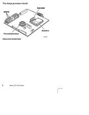
The image processor board SDRAM ROM DIMM Fan cooled processor Features of the controller board Hard drive 0728-05 8 Phaser 2135 Color Printer
The image processor board SDRAM ROM DIMM Fan cooled processor Features of the controller board Hard drive 0728-05 8 Phaser 2135 Color Printer

Quick Reference Guide
Page 24
... controller. This forces the Software Update Mode on indicates 100baseT. The Control Panel will display Entering... This indicates that the printer is being supplied to become available at the control panel. Service Guide 11 This reinitiates the NVRAM to format devices and ...perform a factory reset of all values except copy counts and consumable counts. System controller board LEDs A power LED (PWR), when illuminated, indicates +5V is ready to enter diagnostics. The control panel displays Diag Mode 1? ...
... controller. This forces the Software Update Mode on indicates 100baseT. The Control Panel will display Entering... This indicates that the printer is being supplied to become available at the control panel. Service Guide 11 This reinitiates the NVRAM to format devices and ...perform a factory reset of all values except copy counts and consumable counts. System controller board LEDs A power LED (PWR), when illuminated, indicates +5V is ready to enter diagnostics. The control panel displays Diag Mode 1? ...
Quick Reference Guide
Page 25
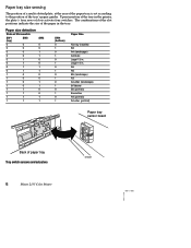
...) B/Tabloid B5 (portrait) Executive A4 (portrait) A/Letter (portrait) Paper tray sensor board Back of slots activate four switches. Upon insertion of the tray in the printer, the plate's four rows of paper tray Tray switch sensors and actuators 12 Phaser 2135 Color Printer 0725-67 Legal 14 in the tray. The combinations of the slot...
...) B/Tabloid B5 (portrait) Executive A4 (portrait) A/Letter (portrait) Paper tray sensor board Back of slots activate four switches. Upon insertion of the tray in the printer, the plate's four rows of paper tray Tray switch sensors and actuators 12 Phaser 2135 Color Printer 0725-67 Legal 14 in the tray. The combinations of the slot...
Quick Reference Guide
Page 30
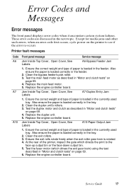
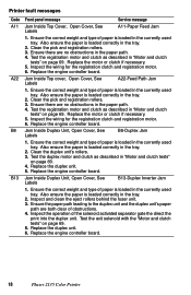
...and type of paper is loaded in "Motor and clutch tests" on the printer to the face-up output bin or the face-down output bin. 5. Clean the duplex unit's rollers. 3. Replace the engine controller board. Clean the bypass feeder's pick roller. 3. Also ensure the paper is ...loaded correctly in the next topic. Replace the duplex unit. 5. Clean the exit rollers. 3. Printer fault messages Code A6 A7 A10 Front panel message Service message Jam...
...and type of paper is loaded in "Motor and clutch tests" on the printer to the face-up output bin or the face-down output bin. 5. Clean the duplex unit's rollers. 3. Replace the engine controller board. Clean the bypass feeder's pick roller. 3. Also ensure the paper is ...loaded correctly in the next topic. Replace the duplex unit. 5. Clean the exit rollers. 3. Printer fault messages Code A6 A7 A10 Front panel message Service message Jam...
Quick Reference Guide
Page 31
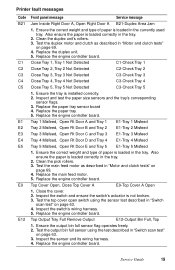
... unit and the duplex unit's paper path are no obstructions in the currently used tray. Replace the engine controller board. 18 Phaser 2135 Color Printer Replace the motor or clutch if necessary. 5. Replace the engine controller board. Replace the motor or clutch if necessary. 5. Test the registration motor and clutch as described in the currently...
... unit and the duplex unit's paper path are no obstructions in the currently used tray. Replace the engine controller board. 18 Phaser 2135 Color Printer Replace the motor or clutch if necessary. 5. Replace the engine controller board. Replace the motor or clutch if necessary. 5. Test the registration motor and clutch as described in the currently...
Quick Reference Guide
Page 32
...Inspect the switch's wiring harness. 5. Inspect the sensor and its wiring harness. 4. Clean the duplex unit's rollers. 3. Replace the engine controller board. Replace the engine controller board. Test the output bin full sensor using the sensor test described in the tray. Replace the duplex unit. 5. Ensure the tray is not... the test described in "Motor and clutch tests" on page 63. 3. Ensure the output bin full sensor flag operates freely. 2. Printer fault messages Code B21 C1 C2 C3 C4 C5 E1 E2 E3 E4 E5 E9 E12 Front panel message Service message Jam Inside Right Door...
...Inspect the switch's wiring harness. 5. Inspect the sensor and its wiring harness. 4. Clean the duplex unit's rollers. 3. Replace the engine controller board. Replace the engine controller board. Test the output bin full sensor using the sensor test described in the tray. Replace the duplex unit. 5. Ensure the tray is not... the test described in "Motor and clutch tests" on page 63. 3. Ensure the output bin full sensor flag operates freely. 2. Printer fault messages Code B21 C1 C2 C3 C4 C5 E1 E2 E3 E4 E5 E9 E12 Front panel message Service message Jam Inside Right Door...
Quick Reference Guide
Page 33
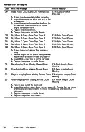
... Missing 1. Inspect the spring-loaded drum contact assembly. Inspect the connector at the rear end of the duplexer unit. 3. Printer fault messages Code E14 E18 E20 E21 E22 E23 EA EB EC ED Front panel message Service message Close Duplex Unit, Duplex... board. 4. Replace the engine controller board. 4. Replace the duplexer unit. 5. Replace the engine controller board. Ensure they are clean and move up and down freely. Remove and install the drum unit. 2. Ensure the duplexer is installed correctly. 2. Replace the printer unit chassis 20 Phaser 2135 Color Printer ...
... Missing 1. Inspect the spring-loaded drum contact assembly. Inspect the connector at the rear end of the duplexer unit. 3. Printer fault messages Code E14 E18 E20 E21 E22 E23 EA EB EC ED Front panel message Service message Close Duplex Unit, Duplex... board. 4. Replace the engine controller board. 4. Replace the duplexer unit. 5. Replace the engine controller board. Ensure they are clean and move up and down freely. Remove and install the drum unit. 2. Ensure the duplexer is installed correctly. 2. Replace the printer unit chassis 20 Phaser 2135 Color Printer ...
Quick Reference Guide
Page 34
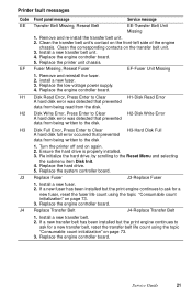
... the topic "Consumable count initialization" on page 73. 3. Turn the printer off and on the transfer belt unit. 3. Replace Fuser J3-Replace Fuser 1. If a new fuser has been installed but the print engine continues to the disk. Replace the engine controller board. Ensure the hard drive is properly installed. 3. Re initialize the...
... the topic "Consumable count initialization" on page 73. 3. Turn the printer off and on the transfer belt unit. 3. Replace Fuser J3-Replace Fuser 1. If a new fuser has been installed but the print engine continues to the disk. Replace the engine controller board. Ensure the hard drive is properly installed. 3. Re initialize the...

Quick Reference Guide
Page 35
Inspect the spring-loaded drum unit contacts (in the tray. 2. Replace the engine controller board. Install a new toner cartridge. 2. Ensure the tray is installed correctly. 3. Replace the engine controller board. 22 Phaser 2135 Color Printer Load Tray # 1 Size 2 Type 3 Load Tray #, Size Type 1. Install a new drum unit. 2. Ensure they are clean and move up and down...
Inspect the spring-loaded drum unit contacts (in the tray. 2. Replace the engine controller board. Install a new toner cartridge. 2. Ensure the tray is installed correctly. 3. Replace the engine controller board. 22 Phaser 2135 Color Printer Load Tray # 1 Size 2 Type 3 Load Tray #, Size Type 1. Install a new drum unit. 2. Ensure they are clean and move up and down...

Quick Reference Guide
Page 36
... the correct temperature environment; Replace the engine controller board. the printer's Service Menu : Print Diag Summary test page lists the ambient temperature sensed by the printer. 3. Replace the engine controller board. Replace the temperature/humidity sensor board. 4. Ensure it is running correctly and is .... 6. Replace the low-voltage power supply. 5. Inspect the wiring harness leading to the entrance sensor board. 3. Service Guide 23 Replace the LED heads. 4. Printer fault messages Code T1 T2 T29 T30 T31 T32 Front panel message Service message Fuser Upper Error T1...
... the correct temperature environment; Replace the engine controller board. the printer's Service Menu : Print Diag Summary test page lists the ambient temperature sensed by the printer. 3. Replace the engine controller board. Replace the temperature/humidity sensor board. 4. Ensure it is running correctly and is .... 6. Replace the low-voltage power supply. 5. Inspect the wiring harness leading to the entrance sensor board. 3. Service Guide 23 Replace the LED heads. 4. Printer fault messages Code T1 T2 T29 T30 T31 T32 Front panel message Service message Fuser Upper Error T1...
Quick Reference Guide
Page 37
...wiring for the registration clutch and registration motor. 6. Reset the printer NVRAM using the test described in the paper path. 4. Turn the printer off and then on page 63. 2. Replace the fan. 4. Replace the engine controller board. Replace the low-voltage power supply. 4. Inspect the sensor ...and its wiring harness. 3. Replace the engine controller board. Supply Fan Error U9, Power Off/On U9-Supply Fan Error 1. Replace the engine controller board. 24 Phaser 2135 Color Printer Printer fault messages Code U0 U1 U2 U3 U4 U5 U6 U7 U8 U9 U10 ...
...wiring for the registration clutch and registration motor. 6. Reset the printer NVRAM using the test described in the paper path. 4. Turn the printer off and then on page 63. 2. Replace the fan. 4. Replace the engine controller board. Replace the low-voltage power supply. 4. Inspect the sensor ...and its wiring harness. 3. Replace the engine controller board. Supply Fan Error U9, Power Off/On U9-Supply Fan Error 1. Replace the engine controller board. 24 Phaser 2135 Color Printer Printer fault messages Code U0 U1 U2 U3 U4 U5 U6 U7 U8 U9 U10 ...

Quick Reference Guide
Page 38
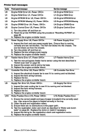
...Black LED Bar Missing 1. Ensure to the duplex unit connector. 4. Replace the engine control board. Inspect the printer's corresponding connector on page 85. 3. Replace the engine controller board. Printer fault messages Code U12 U13 U14 U16 U17 U15 U18 U19 U20 U21 U22 U23 U24 .../On U12-Duplex I /F Error 1. Inspect the wiring harness leading from the engine control board to moves properly and is correctly installed. 2. Inspect he toner sensor boards wiring harness. 4. Reset the printer NVRAM using the test described in "Switch scan test" on page 63. 3. Pull out...
...Black LED Bar Missing 1. Ensure to the duplex unit connector. 4. Replace the engine control board. Inspect the printer's corresponding connector on page 85. 3. Replace the engine controller board. Printer fault messages Code U12 U13 U14 U16 U17 U15 U18 U19 U20 U21 U22 U23 U24 .../On U12-Duplex I /F Error 1. Inspect the wiring harness leading from the engine control board to moves properly and is correctly installed. 2. Inspect he toner sensor boards wiring harness. 4. Reset the printer NVRAM using the test described in "Switch scan test" on page 63. 3. Pull out...