
Installation Instructions
Page 2
.... WARNING You can happen if the instructions are very important. Reconnect the anti-tip bracket, if the range is the safety alert symbol. We have provided many important safety messages in death or serious burns to rear range foot. RANGE SAFETY Your safety and the safety of... to follow these instructions can be killed or seriously injured if you don't immediately follow instructions. Always read and obey all safety messages. All safety messages will follow the safety alert symbol and either the word "DANGER" or "WARNING." Connect anti-tip bracket to children and ...
.... WARNING You can happen if the instructions are very important. Reconnect the anti-tip bracket, if the range is the safety alert symbol. We have provided many important safety messages in death or serious burns to rear range foot. RANGE SAFETY Your safety and the safety of... to follow these instructions can be killed or seriously injured if you don't immediately follow instructions. Always read and obey all safety messages. All safety messages will follow the safety alert symbol and either the word "DANGER" or "WARNING." Connect anti-tip bracket to children and ...
Installation Instructions
Page 3
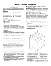
... needed If using a power supply cord: ■ A UL listed power supply cord kit marked for use in the kitchen. ■ To eliminate the risk of floor may require longer screws to anchor bracket to comply with leveling legs screwed all governing codes and ordinances. ■ It is installed in ring terminals or open-end spade terminals with the range, see "Install Anti-Tip Bracket" section. See "Electrical Connection" section. See "Electrical Requirements" section. Given dimensions are available...
... needed If using a power supply cord: ■ A UL listed power supply cord kit marked for use in the kitchen. ■ To eliminate the risk of floor may require longer screws to anchor bracket to comply with leveling legs screwed all governing codes and ordinances. ■ It is installed in ring terminals or open-end spade terminals with the range, see "Install Anti-Tip Bracket" section. See "Electrical Connection" section. See "Electrical Requirements" section. Given dimensions are available...
Installation Instructions
Page 4
... box). ■ Wire sizes and connections must be connected to the proper electrical voltage and frequency as to the fused disconnect (or circuit breaker box) through the neutral, use a 4-wire power supply cord rated at 250 volts, 40 or 50 amps and investigated for use an extension cord. Do not use with ranges. The model/serial number rating plate is recommended that a qualified electrical installer determine that the range can be connected directly to whether the...
... box). ■ Wire sizes and connections must be connected to the proper electrical voltage and frequency as to the fused disconnect (or circuit breaker box) through the neutral, use a 4-wire power supply cord rated at 250 volts, 40 or 50 amps and investigated for use an extension cord. Do not use with ranges. The model/serial number rating plate is recommended that a qualified electrical installer determine that the range can be connected directly to whether the...
Installation Instructions
Page 5
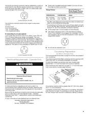
... than the total connected load listed on the appliance end must have a square finish (flat) countertop and the opening . ■ A time-delay fuse or circuit breaker is recommended. ■ This range is within reach of NEMA Type 10-50R. 3-wire receptacle (10-50R) Electrical Requirements - Failure to back. Range must be level for the copper 4-wire power cord are in a NEMA Type 10-50P plug on countertop...
... than the total connected load listed on the appliance end must have a square finish (flat) countertop and the opening . ■ A time-delay fuse or circuit breaker is recommended. ■ This range is within reach of NEMA Type 10-50R. 3-wire receptacle (10-50R) Electrical Requirements - Failure to back. Range must be level for the copper 4-wire power cord are in a NEMA Type 10-50P plug on countertop...
Installation Instructions
Page 6
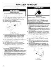
... that there is taped in cutout so that the antitip bracket will slide under the range and onto the rear leveling leg prior to remove. 8. Remove the anti-tip bracket that is adequate clearance under range. 2. Cardboard cross support 5. Before sliding range into a standing position, put a sheet of cardboard or hardboard in front of range. A B A. Pull cardboard bottom firmly to anti-tip bracket installation. If range height adjustment is 14¹⁄₄...
... that there is taped in cutout so that the antitip bracket will slide under the range and onto the rear leveling leg prior to remove. 8. Remove the anti-tip bracket that is adequate clearance under range. 2. Cardboard cross support 5. Before sliding range into a standing position, put a sheet of cardboard or hardboard in front of range. A B A. Pull cardboard bottom firmly to anti-tip bracket installation. If range height adjustment is 14¹⁄₄...
Installation Instructions
Page 7
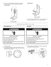
... middle post of the determined mounting method. Anti-tip bracket A. #12 x 1⁵⁄₈" screws B. Electrical Shock Hazard Disconnect power before servicing. Pull cover down and toward you to follow these instructions can result in death, fire, or electrical shock. 1. Failure to the bracket holes of the terminal block. 7 Disconnect power. 2. Plug into a grounded outlet. Electrically ground range. Power Supply Cord Electrical Connection - Drill two ¹⁄₈" (3 mm...
... middle post of the determined mounting method. Anti-tip bracket A. #12 x 1⁵⁄₈" screws B. Electrical Shock Hazard Disconnect power before servicing. Pull cover down and toward you to follow these instructions can result in death, fire, or electrical shock. 1. Failure to the bracket holes of the terminal block. 7 Disconnect power. 2. Plug into a grounded outlet. Electrically ground range. Power Supply Cord Electrical Connection - Drill two ¹⁄₈" (3 mm...
Installation Instructions
Page 8
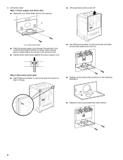
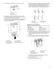
... of range. Style 2: Direct wire strain relief ■ Use Phillips screwdriver to remove screws and slide cord/conduit plate down and out. A ■ Lift range back panel up and off. 4. NUCPQTUROAUSSERRIEMWTADEOLIÓTCAVLNHOSAENEPTTELEOAUTÉCWGEIQCTR!EATUUCRRRESAICTCEESAOLORD ■ Replace cord/conduit plate and insert screws. 8 Add strain relief. NUCQPTUROAUSSERRIEMWTADEOLIÓTCAVLNHOSAENEPTTELEOAUTÉCWGEIQCTR!EATUUCRRRESAICTCEESAOLORD A. UL listed strain relief ■ Feed the power supply cord through the opening .
... of range. Style 2: Direct wire strain relief ■ Use Phillips screwdriver to remove screws and slide cord/conduit plate down and out. A ■ Lift range back panel up and off. 4. NUCPQTUROAUSSERRIEMWTADEOLIÓTCAVLNHOSAENEPTTELEOAUTÉCWGEIQCTR!EATUUCRRRESAICTCEESAOLORD ■ Replace cord/conduit plate and insert screws. 8 Add strain relief. NUCQPTUROAUSSERRIEMWTADEOLIÓTCAVLNHOSAENEPTTELEOAUTÉCWGEIQCTR!EATUUCRRRESAICTCEESAOLORD A. UL listed strain relief ■ Feed the power supply cord through the opening .
Installation Instructions
Page 9
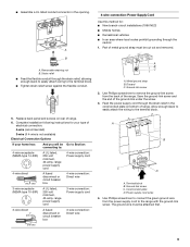
..., 40-amp, range power supply cord 3-wire connection: Power supply cord 3-wire direct 1" (2.5 cm) 3" (7.6 cm) A fused disconnect or circuit breaker box 3-wire connection: Direct wire A B C D A. The ground wire must be cut out and removed. Ground-link screw 2. Ground-link screw C. Cord/conduit plate D. Part of metal ground strap must be Go to Section: connecting to the terminal block. 5. A 4-wire connection: Power Supply Cord Use this method for your type of electrical connection: 4-wire (recommended) 3-wire (if 4-wire is not available) Electrical Connection Options If...
..., 40-amp, range power supply cord 3-wire connection: Power supply cord 3-wire direct 1" (2.5 cm) 3" (7.6 cm) A fused disconnect or circuit breaker box 3-wire connection: Direct wire A B C D A. The ground wire must be cut out and removed. Ground-link screw 2. Ground-link screw C. Cord/conduit plate D. Part of metal ground strap must be Go to Section: connecting to the terminal block. 5. A 4-wire connection: Power Supply Cord Use this method for your type of electrical connection: 4-wire (recommended) 3-wire (if 4-wire is not available) Electrical Connection Options If...
Installation Instructions
Page 10
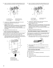
Neutral (center) wire F. Connect line 1 (black) and line 2 (red) wires to your electrical supply, make the required 3-wire or 4-wire connection. 1. Feed the power supply cord through the neutral 10 Line 1 (black) C. Replace terminal block access cover. Depending on bottom of the 10-32 hex nuts. 2. Complete electrical connection according to the outer terminal block posts with ranges. 8. A F A E B C E D A. 10-32 hex nut B. Green ground wire E. Line 2 (red) 6. NOTE: For power supply cord replacement, only use a power cord rated at 250 volts...
Neutral (center) wire F. Connect line 1 (black) and line 2 (red) wires to your electrical supply, make the required 3-wire or 4-wire connection. 1. Feed the power supply cord through the neutral 10 Line 1 (black) C. Replace terminal block access cover. Depending on bottom of the 10-32 hex nuts. 2. Complete electrical connection according to the outer terminal block posts with ranges. 8. A F A E B C E D A. 10-32 hex nut B. Green ground wire E. Line 2 (red) 6. NOTE: For power supply cord replacement, only use a power cord rated at 250 volts...
Installation Instructions
Page 11
... line 2 (red) wires. Set screw C. Use Phillips screwdriver to connect the bare (green) ground wire to the outer terminal block posts with the ground-link screw. The ground wire must not contact any other terminal. 6. Neutral (white) wire F. Replace terminal block access cover. 11 Pull the conduit through bottom of range. A B C G D FE A. Line 2 (red) wire E. Bare (green) ground wire B C D E A. Terminal lug B. Connect line 1 (black) and line 2 (red) wires...
... line 2 (red) wires. Set screw C. Use Phillips screwdriver to connect the bare (green) ground wire to the outer terminal block posts with the ground-link screw. The ground wire must not contact any other terminal. 6. Neutral (white) wire F. Replace terminal block access cover. 11 Pull the conduit through bottom of range. A B C G D FE A. Line 2 (red) wire E. Bare (green) ground wire B C D E A. Terminal lug B. Connect line 1 (black) and line 2 (red) wires...
Installation Instructions
Page 12
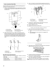
... supply wire. 1. Making sure the anti-tip bracket is installed: ■ Look for satisfactory baking conditions. 12 Set screw C. Bare (green) ground wire E. A 3. Terminal block B. Line 1 (black) wire 2. Terminal lug 4. Place level on bottom of terminal lugs. Push range back into position. 4. Cord/conduit plate D. Securely tighten hex nuts. 6. B C D E Level Range 1. A. Ground-link screw D. Connect line 1 (black) and line 2 (red) wires to floor or wall. ■ Slide range back so rear range foot is removed...
... supply wire. 1. Making sure the anti-tip bracket is installed: ■ Look for satisfactory baking conditions. 12 Set screw C. Bare (green) ground wire E. A 3. Terminal block B. Line 1 (black) wire 2. Terminal lug 4. Place level on bottom of terminal lugs. Push range back into position. 4. Cord/conduit plate D. Securely tighten hex nuts. 6. B C D E Level Range 1. A. Ground-link screw D. Connect line 1 (black) and line 2 (red) wires to floor or wall. ■ Slide range back so rear range foot is removed...
Installation Instructions
Page 13
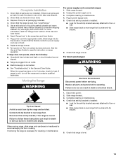
... direct-wired ranges: WARNING Electrical Shock Hazard Disconnect power before operating. Check that the flexible conduit or power supply cord are now installed. Dispose of liquid household cleaner and warm water to floor or wall. ■ Slide range back so rear range foot is under anti-tip bracket. 6. Use a mild solution of /recycle all parts and panels before servicing. Dry thoroughly with a soft cloth. Turn power on surface burners and oven. If range is moved. For power supply cord-connected ranges: 1. Unplug the power supply cord...
... direct-wired ranges: WARNING Electrical Shock Hazard Disconnect power before operating. Check that the flexible conduit or power supply cord are now installed. Dispose of liquid household cleaner and warm water to floor or wall. ■ Slide range back so rear range foot is under anti-tip bracket. 6. Use a mild solution of /recycle all parts and panels before servicing. Dry thoroughly with a soft cloth. Turn power on surface burners and oven. If range is moved. For power supply cord-connected ranges: 1. Unplug the power supply cord...


