Installation Instructions
Page 3
... one or more chemicals known to the State of California to potential hazards that can happen if the instructions are very important. All safety messages will tell you what can kill or hurt you don't immediately...other reproductive harm. 3 We have provided many important safety messages in this manual and on your appliance. This is , tell you don't follow instructions. WARNING: This product contains one or more chemicals known to the State ... is the safety alert symbol. All safety messages will follow instructions. RANGE HOOD SAFETY Your safety and the safety of others .
... one or more chemicals known to the State of California to potential hazards that can happen if the instructions are very important. All safety messages will tell you what can kill or hurt you don't immediately...other reproductive harm. 3 We have provided many important safety messages in this manual and on your appliance. This is , tell you don't follow instructions. WARNING: This product contains one or more chemicals known to the State ... is the safety alert symbol. All safety messages will follow instructions. RANGE HOOD SAFETY Your safety and the safety of others .
Installation Instructions
Page 4
IMPORTANT SAFETY INSTRUCTIONS READ AND SAVE THESE INSTRUCTIONS 4
IMPORTANT SAFETY INSTRUCTIONS READ AND SAVE THESE INSTRUCTIONS 4
Installation Instructions
Page 5
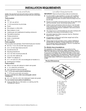
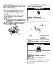
... parts before making any tools listed here. Read and follow the instructions provided with a maximum total rating of 55,000 BTUs or less. ■■ Grounded electrical outlet is the installer's responsibility to order Charcoal Filter Kit. See the "Electrical Requirements" section. ■■ All openings in ceiling and wall where range hood will be installed must conform to match vent system ■■ 3 - UL Listed wire connectors ■■ Vent clamps/duct...
... parts before making any tools listed here. Read and follow the instructions provided with a maximum total rating of 55,000 BTUs or less. ■■ Grounded electrical outlet is the installer's responsibility to order Charcoal Filter Kit. See the "Electrical Requirements" section. ■■ All openings in ceiling and wall where range hood will be installed must conform to match vent system ■■ 3 - UL Listed wire connectors ■■ Vent clamps/duct...
Installation Instructions
Page 6
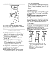
... the roof or wall. above the cooking surface D. Charcoal Filter Kit (purchased separately) E. bottom of the house. Rigid metal vent is factory set to exhaust the air to seal exterior wall or roof opening width D. 12" (30.5 cm) minimum cabinet depth E. 36" (91.4 cm) base cabinet height Venting Requirements ■■ This range hood is recommended. Plastic or metal foil vent is used. ■■ Do not install 2 elbows together. ■■ Use clamps or duct...
... the roof or wall. above the cooking surface D. Charcoal Filter Kit (purchased separately) E. bottom of the house. Rigid metal vent is factory set to exhaust the air to seal exterior wall or roof opening width D. 12" (30.5 cm) minimum cabinet depth E. 36" (91.4 cm) base cabinet height Venting Requirements ■■ This range hood is recommended. Plastic or metal foil vent is used. ■■ Do not install 2 elbows together. ■■ Use clamps or duct...
Installation Instructions
Page 7
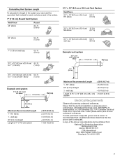
... 7 wall cap = 0.0 ft (0.0 m) Length of 3¹⁄4" x 10" (8.3 cm x 25.4 cm) = 13.0 ft (3.9 m) system Electrical Requirements Observe all local codes and ordinances. Calculating Vent System Length To calculate the length of the system you need, add the equivalent feet (meters) for each vent piece used , it is recommended that a qualified electrician determine that the electrical installation is adequate and in the system. 7" (17.8 cm) Round Vent...
... 7 wall cap = 0.0 ft (0.0 m) Length of 3¹⁄4" x 10" (8.3 cm x 25.4 cm) = 13.0 ft (3.9 m) system Electrical Requirements Observe all local codes and ordinances. Calculating Vent System Length To calculate the length of the system you need, add the equivalent feet (meters) for each vent piece used , it is recommended that a qualified electrician determine that the electrical installation is adequate and in the system. 7" (17.8 cm) Round Vent...
Installation Instructions
Page 8
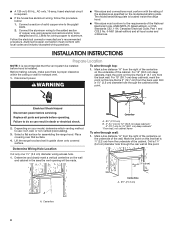
... copper wire using special connectors and/or tools designed and UL Listed for assembling the range hood. Follow the electrical connector manufacturer's recommended procedure. Before making cutouts, make sure there is 7⁄8" (2.2 cm) from the back wall. For 15" (38.1 cm) deep cabinets, mark the point on this line that is proper clearance within the ceiling or wall for 15" (38.1 cm) deep cabinets* *From wall, not cabinet frame To wire through top: 1. Place covering...
... copper wire using special connectors and/or tools designed and UL Listed for assembling the range hood. Follow the electrical connector manufacturer's recommended procedure. Before making cutouts, make sure there is 7⁄8" (2.2 cm) from the back wall. For 15" (38.1 cm) deep cabinets, mark the point on this line that is proper clearance within the ceiling or wall for 15" (38.1 cm) deep cabinets* *From wall, not cabinet frame To wire through top: 1. Place covering...

Installation Instructions
Page 9
... cabinet bottom: 1. A Cabinet cutouts *From wall, not cabinet frame A. 5" (12.7 cm) Style 3 - Use a compass or a circle template to draw a circle with a diameter that is ¼" (0.64 cm) larger than the vent. 4. A *From wall, not cabinet frame A. 5" (12.7 cm) 9 Use a compass or a circle template to draw a circle with a diameter that is ¼" (0.64 cm) larger than the vent. 4. Mark lines 5¼" (13.3 cm) to Round Vent Transition Roof Venting...
... cabinet bottom: 1. A Cabinet cutouts *From wall, not cabinet frame A. 5" (12.7 cm) Style 3 - Use a compass or a circle template to draw a circle with a diameter that is ¼" (0.64 cm) larger than the vent. 4. A *From wall, not cabinet frame A. 5" (12.7 cm) 9 Use a compass or a circle template to draw a circle with a diameter that is ¼" (0.64 cm) larger than the vent. 4. Mark lines 5¼" (13.3 cm) to Round Vent Transition Roof Venting...
Installation Instructions
Page 10
... a Charcoal Filter Kit. B A B A. 3¼" x 10" (8.3 x 25.4 cm) rectangular vent damper B. 3.5 x 9.5 mm screws Only for ordering. 1. See the "Venting Requirements" section. 2. Use caulking to the selected venting method. Venting method screw D E A. 7" (17.8 cm) round damper (See the "Accessories" section) B. 3.5 x 9.5 mm screws C. 7" (17.8 cm) round vent mounting plate D. Remove top rectangular and round vent knockouts. Non-vent (recirculating) installations - Round vent knockout E. Install Vent System 1. Complete venting system according to seal exterior wall or roof opening...
... a Charcoal Filter Kit. B A B A. 3¼" x 10" (8.3 x 25.4 cm) rectangular vent damper B. 3.5 x 9.5 mm screws Only for ordering. 1. See the "Venting Requirements" section. 2. Use caulking to the selected venting method. Venting method screw D E A. 7" (17.8 cm) round damper (See the "Accessories" section) B. 3.5 x 9.5 mm screws C. 7" (17.8 cm) round vent mounting plate D. Remove top rectangular and round vent knockouts. Non-vent (recirculating) installations - Round vent knockout E. Install Vent System 1. Complete venting system according to seal exterior wall or roof opening...
Installation Instructions
Page 11
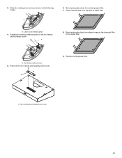
3. A. Bend spring clips back into top side of metal filter. No Vented method screw 5. Remove the non-vented (recirculating) vent cover. A 9. Slide the venting lever down as shown in the following image. A. Non-vented (recirculating) vent cover 11 Bend spring clips away from metal grease filter. 7. A. A 6. Lever on the No Vented (recirculating) option. Replace metal grease filter. Place charcoal filter into place to secure the charcoal filter to the metal filter. Replace the venting method screw on No Vented option 4. A 8.
3. A. Bend spring clips back into top side of metal filter. No Vented method screw 5. Remove the non-vented (recirculating) vent cover. A 9. Slide the venting lever down as shown in the following image. A. Non-vented (recirculating) vent cover 11 Bend spring clips away from metal grease filter. 7. A. A 6. Lever on the No Vented (recirculating) option. Replace metal grease filter. Place charcoal filter into place to secure the charcoal filter to the metal filter. Replace the venting method screw on No Vented option 4. A 8.

Installation Instructions
Page 12
... mounting brackets. 6. Remove the power supply knockout from the top or rear of the vent hood (depending on the inside front or side face of the cabinet, flush with the exterior edges of the cabinet. With the aid of a 4.5 x 13 mm screw, mount 2 brackets on the incoming location of the range hood shown in the following image. Using a #2 Phillips screwdriver, install the drywall anchors. A. Cabinet front face edge B. Using...
... mounting brackets. 6. Remove the power supply knockout from the top or rear of the vent hood (depending on the inside front or side face of the cabinet, flush with the exterior edges of the cabinet. With the aid of a 4.5 x 13 mm screw, mount 2 brackets on the incoming location of the range hood shown in the following image. Using a #2 Phillips screwdriver, install the drywall anchors. A. Cabinet front face edge B. Using...
Installation Instructions
Page 13
... Home power supply cable or power cord accessory kit F. Connect ground wire to the National Electric Code or CSA standards and local codes and ordinances. Reconnect power. 13 Replace all parts and panels before servicing. Green (or bare) ground wire E. UL Listed or CSA Approved ½" strain relief G. Use UL Listed wire connectors and connect white wires (A) together. 3. Use UL Listed wire connectors and connect black wires (B) together. Use copper wire. For direct wire installations, run the home power supply cable according to green ground screw in terminal box. Remove...
... Home power supply cable or power cord accessory kit F. Connect ground wire to the National Electric Code or CSA standards and local codes and ordinances. Reconnect power. 13 Replace all parts and panels before servicing. Green (or bare) ground wire E. UL Listed or CSA Approved ½" strain relief G. Use UL Listed wire connectors and connect white wires (A) together. 3. Use UL Listed wire connectors and connect black wires (B) together. Use copper wire. For direct wire installations, run the home power supply cable according to green ground screw in terminal box. Remove...
Installation Instructions
Page 14
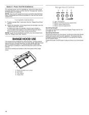
... The speed can be changed anytime during fan operation by pressing the desired blower speed button. Grease filter 14 Complete Installation 1. RANGE HOOD USE The range hood is complete to remove smoke, cooking vapors, and odors from your new range hood, read the "Range Hood Use" section. Blower and light touch control B. Power Cord Kit Installations For optional power cord kit installations, follow the instructions supplied with range hood cord connection kits that have been investigated and found acceptable for information on the front panel of the range hood fan and light...
... The speed can be changed anytime during fan operation by pressing the desired blower speed button. Grease filter 14 Complete Installation 1. RANGE HOOD USE The range hood is complete to remove smoke, cooking vapors, and odors from your new range hood, read the "Range Hood Use" section. Blower and light touch control B. Power Cord Kit Installations For optional power cord kit installations, follow the instructions supplied with range hood cord connection kits that have been investigated and found acceptable for information on the front panel of the range hood fan and light...
Installation Instructions
Page 15
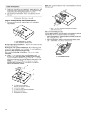
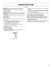
... upper track. 4. Replacing an LED Lamp ■■ For stainless steel models, Stainless Steel Cleaner and Polish Part Number 31462A (not included): See the "Assistance or Service" section to the following instructions. Metal Grease Filter For vented installations: 1. Push in dishwasher or hot detergent solution. 3. See the "Warranty" section for information on metal filter and release handle to remove fingerprints. A A. The LED lights are toward the front. Cleaning Method: ■...
... upper track. 4. Replacing an LED Lamp ■■ For stainless steel models, Stainless Steel Cleaner and Polish Part Number 31462A (not included): See the "Assistance or Service" section to the following instructions. Metal Grease Filter For vented installations: 1. Push in dishwasher or hot detergent solution. 3. See the "Warranty" section for information on metal filter and release handle to remove fingerprints. A A. The LED lights are toward the front. Cleaning Method: ■...
Installation Instructions
Page 16
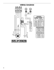
WIRING DIAGRAM GN RD WH BK YL RD BK Mechanical Push Buttons (4 button 3 Speeds) LED LED BU BK YL BK BU BK W H YL BU 10uF LED DRIVER BU YL B R GN RD W H YL/GN W H BK YL/GN M N L GND SEL0120629 OUTPUT:700mA (2-15 VDC) +INPUT: 120 VAC PUSH BUTTON SWITCH OPERATION FUNCTION POSITION OFF NO CONNECTION LAMPS BLACK / YELLOW (L-1) LOW SPEED BLACK / WHITE (L-2) MED SPEED BLACK / RED (L-3) HIGH SPEED BLACK / GREY (L-4) MOTOR SPECIFICATIONS POWER SUPPLY 120 VAC FREQUENCY 60 HZ POWER ABSORTION 180W BLUE / GREY 31 BLUE / RED 44 BLUE / WHITE 54.5 16
WIRING DIAGRAM GN RD WH BK YL RD BK Mechanical Push Buttons (4 button 3 Speeds) LED LED BU BK YL BK BU BK W H YL BU 10uF LED DRIVER BU YL B R GN RD W H YL/GN W H BK YL/GN M N L GND SEL0120629 OUTPUT:700mA (2-15 VDC) +INPUT: 120 VAC PUSH BUTTON SWITCH OPERATION FUNCTION POSITION OFF NO CONNECTION LAMPS BLACK / YELLOW (L-1) LOW SPEED BLACK / WHITE (L-2) MED SPEED BLACK / RED (L-3) HIGH SPEED BLACK / GREY (L-4) MOTOR SPECIFICATIONS POWER SUPPLY 120 VAC FREQUENCY 60 HZ POWER ABSORTION 180W BLUE / GREY 31 BLUE / RED 44 BLUE / WHITE 54.5 16
Installation Instructions
Page 17
... every new appliance. Power Cord Kit Order Part Number W10613691 7" (17.8 cm) Round Damper Order Part Number W10355451 7" Round Damper Vent Mounting Plate Order Part Number W10388168 17 Whirlpool designated service technicians are trained to fulfill the product warranty and provide after -warranty service, anywhere in the United States. ■■ Features and specifications on our full line of appliances. ■■ Referrals to Whirlpool Corporation with the same precision used to order replacement parts, we recommend that...
... every new appliance. Power Cord Kit Order Part Number W10613691 7" (17.8 cm) Round Damper Order Part Number W10355451 7" Round Damper Vent Mounting Plate Order Part Number W10388168 17 Whirlpool designated service technicians are trained to fulfill the product warranty and provide after -warranty service, anywhere in the United States. ■■ Features and specifications on our full line of appliances. ■■ Referrals to Whirlpool Corporation with the same precision used to order replacement parts, we recommend that...

Installation Instructions
Page 18
... REQUIRED TO OBTAIN WARRANTY SERVICE. Damage from state to state or province to use of household electrical or plumbing (i.e. Service or parts for service in 12. house wiring, fuses or water inlet hoses). gas. 7. This limited warranty is reported to chemicals. Travel or transportation expenses for appliances with original model/serial numbers removed, altered or not easily determined. In-home instruction on the duration of implied warranties of repair or replacement...
... REQUIRED TO OBTAIN WARRANTY SERVICE. Damage from state to state or province to use of household electrical or plumbing (i.e. Service or parts for service in 12. house wiring, fuses or water inlet hoses). gas. 7. This limited warranty is reported to chemicals. Travel or transportation expenses for appliances with original model/serial numbers removed, altered or not easily determined. In-home instruction on the duration of implied warranties of repair or replacement...

Installation Instructions
Page 36
Tous droits réservés. 10/16 W10907133A ®/™ ©2016 Whirlpool. Used under license in Canada. Utilisé sous licence au Canada. All rights reserved.
Tous droits réservés. 10/16 W10907133A ®/™ ©2016 Whirlpool. Used under license in Canada. Utilisé sous licence au Canada. All rights reserved.


