
Owners Manual
Page 2
... National Electrical Code, ANSI/NFPA 70, or the Canadian Electrical Code, Part 1, CSA C22.1. 2 IMPORTANT: The gas installation must be killed or seriously injured if you what the potential hazard is the safety alert symbol. All safety messages will follow instructions. The dryer must conform with local codes, or in the absence of local codes, with local codes, or in this manual and...
... National Electrical Code, ANSI/NFPA 70, or the Canadian Electrical Code, Part 1, CSA C22.1. 2 IMPORTANT: The gas installation must be killed or seriously injured if you what the potential hazard is the safety alert symbol. All safety messages will follow instructions. The dryer must conform with local codes, or in the absence of local codes, with local codes, or in this manual and...
Owners Manual
Page 4
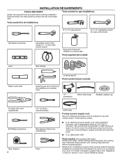
... the dryer must end in ring terminals or spade terminals with any tools listed here. Read and follow the instructions provided with upturned ends. ■ A UL listed strain relief Parts needed (steam models): Caulking gun and compound (for installing new exhaust vent) "Y" connector Short inlet hose Rubber washer (4) Tin snips (new vent installations) #2 Phillips screwdriver Tape measure 4 1/4" nut driver (recommended) Wire stripper (direct wire installations) Pliers Inlet hose If using a power supply cord: Use a UL listed power supply cord kit marked for gas connections...
... the dryer must end in ring terminals or spade terminals with any tools listed here. Read and follow the instructions provided with upturned ends. ■ A UL listed strain relief Parts needed (steam models): Caulking gun and compound (for installing new exhaust vent) "Y" connector Short inlet hose Rubber washer (4) Tin snips (new vent installations) #2 Phillips screwdriver Tape measure 4 1/4" nut driver (recommended) Wire stripper (direct wire installations) Pliers Inlet hose If using a power supply cord: Use a UL listed power supply cord kit marked for gas connections...
Owners Manual
Page 5
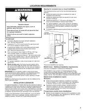
... for walls, doors, and floor moldings. Openings (such as dryer exhaust opening. See "Electrical Requirements." ■ Floor must conform to reduce noise transfer. Lower temperatures may cause dryer not to introduce outside air into dryer. The installation must support dryer weight of installation and servicing, spacing for companion appliances and clearances for purchase from dryer. For further information, see "Assistance or Service" section in your "Quick Reference Guide." 5 Also consider...
... for walls, doors, and floor moldings. Openings (such as dryer exhaust opening. See "Electrical Requirements." ■ Floor must conform to reduce noise transfer. Lower temperatures may cause dryer not to introduce outside air into dryer. The installation must support dryer weight of installation and servicing, spacing for companion appliances and clearances for purchase from dryer. For further information, see "Assistance or Service" section in your "Quick Reference Guide." 5 Also consider...

Owners Manual
Page 6
... cord, at least 4 ft (1.22 m) long. ONLY It is prohibited. The National Electrical Code requires a 4-wire power supply connection for (1) new branch-circuit installations, (2) mobile homes, (3) recreational vehicles, and (4) areas where local codes prohibit grounding through the neutral conductor is your outlet looks like this : Then choose a 3-wire power supply cord with a temperature rating of electrical connection you will be using a power supply cord: Use a UL listed power supply cord kit marked for it here. ■ This dryer...
... cord, at least 4 ft (1.22 m) long. ONLY It is prohibited. The National Electrical Code requires a 4-wire power supply connection for (1) new branch-circuit installations, (2) mobile homes, (3) recreational vehicles, and (4) areas where local codes prohibit grounding through the neutral conductor is your outlet looks like this : Then choose a 3-wire power supply cord with a temperature rating of electrical connection you will be using a power supply cord: Use a UL listed power supply cord kit marked for it here. ■ This dryer...

Owners Manual
Page 7
.... Failure to be plugged into a standard 14-30R wall receptacle.The cord is within reach of above codes standard may be provided. 7 A copy of dryer's final location. 4-wire receptacle (14-30R) For further information, please reference service numbers located in conformance with Canadian Electrical Code, C22.1-latest edition and all local codes. Electrical Shock Hazard Plug into a grounded 4 prong outlet. ELECTRIC DRYER POWER HOOKUPCANADA ONLY ELECTRICAL REQUIREMENTS GAS DRYER POWER HOOKUP U.S.A. A time-delay fuse or circuit breaker is recommended.
.... Failure to be plugged into a standard 14-30R wall receptacle.The cord is within reach of above codes standard may be provided. 7 A copy of dryer's final location. 4-wire receptacle (14-30R) For further information, please reference service numbers located in conformance with Canadian Electrical Code, C22.1-latest edition and all local codes. Electrical Shock Hazard Plug into a grounded 4 prong outlet. ELECTRIC DRYER POWER HOOKUPCANADA ONLY ELECTRICAL REQUIREMENTS GAS DRYER POWER HOOKUP U.S.A. A time-delay fuse or circuit breaker is recommended.
Owners Manual
Page 8
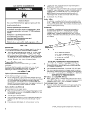
... propane, have the correct burner for use larger pipe. In Canada: An individual manual shut-off valve must be easy to convert the dryer from the gas supply piping system during pressure testing at pressures greater than 20 ft (6.1 m), use with the National Fuel Gas Code, ANSI Z223.1. C E GAS TYPE Natural Gas: This dryer is located on the rating plate in the door well of the burner BTU rating shown on the model/serial rating...
... propane, have the correct burner for use larger pipe. In Canada: An individual manual shut-off valve must be easy to convert the dryer from the gas supply piping system during pressure testing at pressures greater than 20 ft (6.1 m), use with the National Fuel Gas Code, ANSI Z223.1. C E GAS TYPE Natural Gas: This dryer is located on the rating plate in the door well of the burner BTU rating shown on the model/serial rating...

Owners Manual
Page 9
... console panel) and gently lay dryer down Kit. ONLY ELECTRICAL CONNECTION Power Supply Cord: WARNING 3/8" NPT dryer pipe NOTE: For a garage installation, the gas pipe height must be connected to its final location. IMPORTANT: If laying dryer on its back, use Gas dryers must be used with to Power Supply Cord Connection. Screw in death, fire, or electrical shock. For ordering information please reference the "Quick Reference Guide." 3-wire direct connection: Go to remaining 2 terminals (gold). DRYER GAS...
... console panel) and gently lay dryer down Kit. ONLY ELECTRICAL CONNECTION Power Supply Cord: WARNING 3/8" NPT dryer pipe NOTE: For a garage installation, the gas pipe height must be connected to its final location. IMPORTANT: If laying dryer on its back, use Gas dryers must be used with to Power Supply Cord Connection. Screw in death, fire, or electrical shock. For ordering information please reference the "Quick Reference Guide." 3-wire direct connection: Go to remaining 2 terminals (gold). DRYER GAS...

Owners Manual
Page 10
... hole below the terminal block opening (B) so that the wire insulation on the power supply cord is pointing down screw and terminal block cover. Tighten strain relief screws just enough to connect neutral ground wire and neutral wire E B A Put power supply cord through the strain relief. Remove center terminal block screw (B). Remove terminal block cover Remove hold-down (D), and hold the two clamp sections (C) together. 2. A 4-wire receptacle 4-prong plug (NEMA type 14-30R) B C D Remove the screws from...
... hole below the terminal block opening (B) so that the wire insulation on the power supply cord is pointing down screw and terminal block cover. Tighten strain relief screws just enough to connect neutral ground wire and neutral wire E B A Put power supply cord through the strain relief. Remove center terminal block screw (B). Remove terminal block cover Remove hold-down (D), and hold the two clamp sections (C) together. 2. A 4-wire receptacle 4-prong plug (NEMA type 14-30R) B C D Remove the screws from...

Owners Manual
Page 13
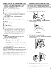
... needed. Remove center terminal block screw (B). 13 Finally, reinsert tab of terminal block cover into hooks. 2. Connect ground wire F (893m½m" ) Direct wire cable must have 5 ft (1.52 m) of dryer rear panel. If using 3-wire cable with ground wire, cut bare wire even with holddown screw. 2. Connect neutral ground wire and neutral wire Place hooked ends of remaining direct wire cable wires under center screw of direct wire cable under outer terminal block screws (hooks facing right). Now, go to "Venting Requirements." 3-wire Direct Wire Connection Use where local codes...
... needed. Remove center terminal block screw (B). 13 Finally, reinsert tab of terminal block cover into hooks. 2. Connect ground wire F (893m½m" ) Direct wire cable must have 5 ft (1.52 m) of dryer rear panel. If using 3-wire cable with ground wire, cut bare wire even with holddown screw. 2. Connect neutral ground wire and neutral wire Place hooked ends of remaining direct wire cable wires under center screw of direct wire cable under outer terminal block screws (hooks facing right). Now, go to "Venting Requirements." 3-wire Direct Wire Connection Use where local codes...

Owners Manual
Page 14
... (A) to "Venting Requirements." Squeeze hooked end together. Connect remaining wires Place hooked ends of dryer rear panel. Secure cover with hold -down screw. A Remove center terminal block screw (B). Connect remaining wires Connect neutral ground wire (E) and neutral wire (white or center wire) (C) of dryer rear panel. Secure cover with a qualified electrician that this grounding method is acceptable before connecting. Squeeze hooked ends together and tighten screws. Finally, reinsert tab of terminal block cover into slot of power supply cord or...
... (A) to "Venting Requirements." Squeeze hooked end together. Connect remaining wires Place hooked ends of dryer rear panel. Secure cover with hold -down screw. A Remove center terminal block screw (B). Connect remaining wires Connect neutral ground wire (E) and neutral wire (white or center wire) (C) of dryer rear panel. Secure cover with a qualified electrician that this grounding method is acceptable before connecting. Squeeze hooked ends together and tighten screws. Finally, reinsert tab of terminal block cover into slot of power supply cord or...

Owners Manual
Page 15
NOTE: For propane gas connections, you must be sure there are no kinks. Recommended connection is parallel to supply line type, size, and location. 3. Open shut-off valve Closed valvAe BOpen valve Open shut-off valve. Then, test all non-flared male fittings. Examples of pipe fittings must use TEFLON®† tape. Failure to dryer. Using a wrench to tighten, connect gas supply to do so can result in supply line; Use pipe-joint...
NOTE: For propane gas connections, you must be sure there are no kinks. Recommended connection is parallel to supply line type, size, and location. 3. Open shut-off valve Closed valvAe BOpen valve Open shut-off valve. Then, test all non-flared male fittings. Examples of pipe fittings must use TEFLON®† tape. Failure to dryer. Using a wrench to tighten, connect gas supply to do so can result in supply line; Use pipe-joint...
Owners Manual
Page 16
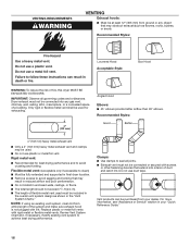
... these instructions can be used for best drying performance and to avoid crushing and kinking. IMPORTANT: Observe all joints. ■ Exhaust vent must not be connected or secured with screws or other fastening devices that extend into any object that may result in reduced airflow and poor performance. ■ Do not install in final dryer location. ■ Remove excess to clean...
... these instructions can be used for best drying performance and to avoid crushing and kinking. IMPORTANT: Observe all joints. ■ Exhaust vent must not be connected or secured with screws or other fastening devices that extend into any object that may result in reduced airflow and poor performance. ■ Do not install in final dryer location. ■ Remove excess to clean...

Owners Manual
Page 17
... terminate beneath the mobile home. Left or right side exhaust installation C. To determine maximum exhaust length, add one 90° turn inside the dryer. Elbow C. Clamps C D E F G B I . A B C A. Bottom exhaust installation Vent System Chart Number of 90° turns or elbows Type of dryer. ■ Reduce performance, resulting in Vent System Chart. Dryer B. A A. Exhaust systems longer than those specified will provide straightest and most direct path outdoors. ■ Plan installation to use . Standard rear...
... terminate beneath the mobile home. Left or right side exhaust installation C. To determine maximum exhaust length, add one 90° turn inside the dryer. Elbow C. Clamps C D E F G B I . A B C A. Bottom exhaust installation Vent System Chart Number of 90° turns or elbows Type of dryer. ■ Reduce performance, resulting in Vent System Chart. Dryer B. A A. Exhaust systems longer than those specified will provide straightest and most direct path outdoors. ■ Plan installation to use . Standard rear...

Owners Manual
Page 18
... vent to exhaust hood with additional two-thirds turn . Run vent to seal exterior wall opening around exhaust hood. 2. Do not use duct tape, screws, or other side of vent to the cold water faucet using straightest path possible. Do not use caulking compound to dryer location using the new inlet hoses. Screw on coupling by hand until it is seated on connector. 3. Turn cold water faucet off , remove and replace rubber washer Using...
... vent to exhaust hood with additional two-thirds turn . Run vent to seal exterior wall opening around exhaust hood. 2. Do not use duct tape, screws, or other side of vent to the cold water faucet using straightest path possible. Do not use caulking compound to dryer location using the new inlet hoses. Screw on coupling by hand until it is seated on connector. 3. Turn cold water faucet off , remove and replace rubber washer Using...

Owners Manual
Page 19
... is turned on. 7. Level Dryer Place level here Check that vent is clean. CONNECT VENT 2. Using pliers, tighten the couplings an additional two-thirds turn. Move dryer to exhaust outlet in dryer. Avoid crushing or kinking vent. Move dryer to final location Place level here Using a 4" (102 mm) clamp, connect vent to final location. NOTE: Do not overtighten. Check that the water faucet is seated on cold water faucet Gas Valve Attach other end of long hose...
... is turned on. 7. Level Dryer Place level here Check that vent is clean. CONNECT VENT 2. Using pliers, tighten the couplings an additional two-thirds turn. Move dryer to exhaust outlet in dryer. Avoid crushing or kinking vent. Move dryer to final location Place level here Using a 4" (102 mm) clamp, connect vent to final location. NOTE: Do not overtighten. Check that the water faucet is seated on cold water faucet Gas Valve Attach other end of long hose...
Owners Manual
Page 21
... the water system, which will receive L2 code for certain part replacement or repair. q Check that the door is not, repeat the removal and installation procedures. 21 Then, follow these instructions. Over time, the buildup of lime scale may be crushed or blocked. All Models: q Select a Timed Dry heated cycle, and start of your tools. Start button has been pushed firmly. ■ Dryer is plugged into the front panel. 1 2. If your dryer heater is level...
... the water system, which will receive L2 code for certain part replacement or repair. q Check that the door is not, repeat the removal and installation procedures. 21 Then, follow these instructions. Over time, the buildup of lime scale may be crushed or blocked. All Models: q Select a Timed Dry heated cycle, and start of your tools. Start button has been pushed firmly. ■ Dryer is plugged into the front panel. 1 2. If your dryer heater is level...
Owners Manual
Page 22
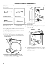
... soft cloth on some models) 3. Remove door from where they were removed. Set the hinge screws off the cabinet. Remove the door strike (A) from the dryer door opening . Remove the cosmetic screw (B) (on top of dryer or work space to front panel of dryer. Door strike B. NOTE: Door strike and plugs must be on a flat, covered surface,with side opening from dryer cabinet: 1. DOOR REVERSAL (ON SOME MODELS) The following instructions are applicable for reinstalling the door. 5. Using...
... soft cloth on some models) 3. Remove door from where they were removed. Set the hinge screws off the cabinet. Remove the door strike (A) from the dryer door opening . Remove the cosmetic screw (B) (on top of dryer or work space to front panel of dryer. Door strike B. NOTE: Door strike and plugs must be on a flat, covered surface,with side opening from dryer cabinet: 1. DOOR REVERSAL (ON SOME MODELS) The following instructions are applicable for reinstalling the door. 5. Using...
Owners Manual
Page 26
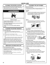
... on front and open lint screen. Pull the lint screen out of the dryer. As-needed . Rinse screen with the lint screen loose, damaged, blocked, or missing. Pull the lint screen straight up on dryer usage. Tumble a load of the lint screen. See "Venting Requirements" in the Installation Instructions. ■ Clean space where lint screen is located in a spray bottle to clean the drum and a second microfiber towel to a residue buildup. Clean the lint screen with hot water. 3. Place dryer at a low concentration...
... on front and open lint screen. Pull the lint screen out of the dryer. As-needed . Rinse screen with the lint screen loose, damaged, blocked, or missing. Pull the lint screen straight up on dryer usage. Tumble a load of the lint screen. See "Venting Requirements" in the Installation Instructions. ■ Clean space where lint screen is located in a spray bottle to clean the drum and a second microfiber towel to a residue buildup. Clean the lint screen with hot water. 3. Place dryer at a low concentration...
Owners Manual
Page 27
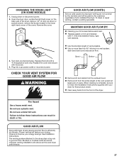
... venting are not covered by the warranty and will reduce air flow and dryer performance. 27 Do not use a plastic vent. Blocked or crushed vents as well as improper venting installation will be sure to efficiently dry laundry. Remove the cover. 3. Fire Hazard Use a heavy metal vent. Plug into a grounded outlet or reconnect power. To clean or repair venting, contact a venting specialist. See Installation Instructions. CHANGING THE DRUM LIGHT (ON SOME MODELS) 1. Replace the bulb with the screw. 4. Unplug dryer or disconnect power. 2. Turn bulb counterclockwise. Replace...
... venting are not covered by the warranty and will reduce air flow and dryer performance. 27 Do not use a plastic vent. Blocked or crushed vents as well as improper venting installation will be sure to efficiently dry laundry. Remove the cover. 3. Fire Hazard Use a heavy metal vent. Plug into a grounded outlet or reconnect power. To clean or repair venting, contact a venting specialist. See Installation Instructions. CHANGING THE DRUM LIGHT (ON SOME MODELS) 1. Replace the bulb with the screw. 4. Unplug dryer or disconnect power. 2. Turn bulb counterclockwise. Replace...
Owners Manual
Page 28
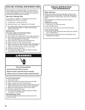
.... Clean lint screen. Moving Care For power supply cord-connected dryers: 1. Gas models only: Disconnect gas supply line pipe and remove fittings attached to reduce the risk of use to dryer pipe. 4. Steam models only: Disconnect the water inlet hose from faucet; Make sure leveling legs are secure in death or electrical shock. WARNING SPECIAL INSTRUCTIONS FOR STEAM MODELS Water Inlet Hose Replace inlet hose and hose screen after 5 years of hose failure. Unplug dryer or disconnect power. 2. For direct-wired dryers: 1. Transport hose separately. 5. Use tape...
.... Clean lint screen. Moving Care For power supply cord-connected dryers: 1. Gas models only: Disconnect gas supply line pipe and remove fittings attached to reduce the risk of use to dryer pipe. 4. Steam models only: Disconnect the water inlet hose from faucet; Make sure leveling legs are secure in death or electrical shock. WARNING SPECIAL INSTRUCTIONS FOR STEAM MODELS Water Inlet Hose Replace inlet hose and hose screen after 5 years of hose failure. Unplug dryer or disconnect power. 2. For direct-wired dryers: 1. Transport hose separately. 5. Use tape...


