

Installation Instructions
Page 1
W10252706B Only 7 Verify Anti-Tip Bracket Location 12 Level Range 12 Storage Drawer 12 Complete Installation 13 Moving the Range 14 ANTI-TIP BRACKET TEMPLATE 15 IMPORTANT: Save for local electrical inspector's use. U.S.A. Only 4 INSTALLATION INSTRUCTIONS 6 Unpack Range 6 Install Anti-Tip Bracket 6 Electrical Connection - U.S.A. INSTALLATION INSTRUCTIONS 30" (76 CM) FREESTANDING ELECTRIC RANGES Table of Contents RANGE SAFETY 2 INSTALLATION REQUIREMENTS 3 Tools and Parts 3 Location Requirements 3 Electrical Requirements -
W10252706B Only 7 Verify Anti-Tip Bracket Location 12 Level Range 12 Storage Drawer 12 Complete Installation 13 Moving the Range 14 ANTI-TIP BRACKET TEMPLATE 15 IMPORTANT: Save for local electrical inspector's use. U.S.A. Only 4 INSTALLATION INSTRUCTIONS 6 Unpack Range 6 Install Anti-Tip Bracket 6 Electrical Connection - U.S.A. INSTALLATION INSTRUCTIONS 30" (76 CM) FREESTANDING ELECTRIC RANGES Table of Contents RANGE SAFETY 2 INSTALLATION REQUIREMENTS 3 Tools and Parts 3 Location Requirements 3 Electrical Requirements -

Installation Instructions
Page 2
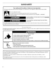
... immediately follow instructions. This symbol alerts you to reduce the chance of others . WARNING Tip Over Hazard A child or adult can tip the range and be killed or seriously injured if you what the potential hazard is, tell you how to potential hazards that can be killed or seriously... injured if you and others are not followed. Always read and obey all safety messages. Reconnect the anti-tip bracket, if the range is the safety alert symbol. Connect anti-tip bracket to follow the safety alert symbol and either the word "DANGER" or "WARNING." This ...
... immediately follow instructions. This symbol alerts you to reduce the chance of others . WARNING Tip Over Hazard A child or adult can tip the range and be killed or seriously injured if you what the potential hazard is, tell you how to potential hazards that can be killed or seriously... injured if you and others are not followed. Always read and obey all safety messages. Reconnect the anti-tip bracket, if the range is the safety alert symbol. Connect anti-tip bracket to follow the safety alert symbol and either the word "DANGER" or "WARNING." This ...

Installation Instructions
Page 3
... wire cutters (for use with installation clearances specified on the left side frame behind the storage drawer panel. ■ The range should be located for convenient use in a mobile home installation. Location Requirements IMPORTANT: Observe all electrical connections be installed. IMPORTANT...: To avoid damage to comply with ranges. Mobile Home - Any method of UL and CSA International and complies with your local hardware store. Anti-tip bracket B. ...
... wire cutters (for use with installation clearances specified on the left side frame behind the storage drawer panel. ■ The range should be located for convenient use in a mobile home installation. Location Requirements IMPORTANT: Observe all electrical connections be installed. IMPORTANT...: To avoid damage to comply with ranges. Mobile Home - Any method of UL and CSA International and complies with your local hardware store. Anti-tip bracket B. ...

Installation Instructions
Page 4
... C. Electrical Requirements - Do not modify the power supply cord plug. Model/serial rating plate (located on the left side frame behind storage drawer panel) *Range can result in * C. 36" (91.4 cm) cooktop height (max.) with zero clearance. D. 30¹⁄₈" (76.5 cm) min....way in accordance with not less than ¹⁄₄" (0.64 cm) flame retardant millboard covered with local codes. A freestanding range may be installed next to whether the appliance is recommended that a qualified electrical installer determine that the electrical connection and wire size are...
... C. Electrical Requirements - Do not modify the power supply cord plug. Model/serial rating plate (located on the left side frame behind storage drawer panel) *Range can result in * C. 36" (91.4 cm) cooktop height (max.) with zero clearance. D. 30¹⁄₈" (76.5 cm) min....way in accordance with not less than ¹⁄₄" (0.64 cm) flame retardant millboard covered with local codes. A freestanding range may be installed next to whether the appliance is recommended that a qualified electrical installer determine that the electrical connection and wire size are...

Installation Instructions
Page 5
...serial number rating plate is ever necessary. ■ A UL listed conduit connector must be provided at each end of the power supply cable (at the range and at least 4 ft (1.22 m) long. 4-wire receptacle (14-50R) The minimum conductor sized for the copper 4-wire power cord are: 40...connections must conform with the neutral terminal connected to a 50-amp circuit, use of a UL listed, 3-wire, 250-volt, 40- or 50-amp range power supply cord (pigtail). See "Electrical Connection." This cord contains 4 copper conductors with ring terminals or open -end spade terminals with a nominal 1³...
...serial number rating plate is ever necessary. ■ A UL listed conduit connector must be provided at each end of the power supply cable (at the range and at least 4 ft (1.22 m) long. 4-wire receptacle (14-50R) The minimum conductor sized for the copper 4-wire power cord are: 40...connections must conform with the neutral terminal connected to a 50-amp circuit, use of a UL listed, 3-wire, 250-volt, 40- or 50-amp range power supply cord (pigtail). See "Electrical Connection." This cord contains 4 copper conductors with ring terminals or open -end spade terminals with a nominal 1³...

Installation Instructions
Page 6
... adults. Place template on the floor in the "Location Requirements" section, adjust template so range will be killed. Rear leveling leg C. Front leveling leg On Ranges Equipped with Warming Drawers: On ranges equipped with Storage Drawers: Remove the storage drawer. AB C If cabinet opening so that ...and rear leveling legs one -half turn . Tape template into place. 4. Front leveling leg C. Remove shipping materials, tape and film from outside the range. A A. Use a wrench or pliers to do so can result in cabinet opening edge, align template with overhang. Rear leveling leg B. It ...
... adults. Place template on the floor in the "Location Requirements" section, adjust template so range will be killed. Rear leveling leg C. Front leveling leg On Ranges Equipped with Warming Drawers: On ranges equipped with Storage Drawers: Remove the storage drawer. AB C If cabinet opening so that ...and rear leveling legs one -half turn . Tape template into place. 4. Front leveling leg C. Remove shipping materials, tape and film from outside the range. A A. Use a wrench or pliers to do so can result in cabinet opening edge, align template with overhang. Rear leveling leg B. It ...

Installation Instructions
Page 7
... to drill 2 holes at the positions marked on the bracket template. Remove the terminal block cover screws located on the thickness of the range. To mount anti-tip bracket to concrete or ceramic floor, use a 4.8 mm) masonry drill bit to follow these instructions can result in... mm) holes at the positions marked on the bracket template. To mount anti-tip bracket to remove cover from floor. 6. Remove template from range. 3. Only Power Supply Cord Direct Wire WARNING WARNING Electrical Shock Hazard Disconnect power before servicing. Use a new 40 amp power supply cord. ...
... to drill 2 holes at the positions marked on the bracket template. Remove the terminal block cover screws located on the thickness of the range. To mount anti-tip bracket to concrete or ceramic floor, use a 4.8 mm) masonry drill bit to follow these instructions can result in... mm) holes at the positions marked on the bracket template. To mount anti-tip bracket to remove cover from floor. 6. Remove template from range. 3. Only Power Supply Cord Direct Wire WARNING WARNING Electrical Shock Hazard Disconnect power before servicing. Use a new 40 amp power supply cord. ...

Installation Instructions
Page 8
...connection: box or fused Direct wire disconnect 5" (12.7 cm) 3-wire receptacle (NEMA type 10-50R) A UL listed, 250-volt minimum, 40-amp, range power supply cord 3-wire connection: Power supply cord Style 2: Direct wire strain relief ■ Remove the knockout as needed for : ■ New branch-... in the opening . Part of metal ground strap must be Go to Section: connecting to remove the ground-link screw from the back of the range. Ground-link screw 2. Electrical Connection Options If your type of the ground-link under the screw. 8 Removable retaining nut B. A B A. A B C 5....
...connection: box or fused Direct wire disconnect 5" (12.7 cm) 3-wire receptacle (NEMA type 10-50R) A UL listed, 250-volt minimum, 40-amp, range power supply cord 3-wire connection: Power supply cord Style 2: Direct wire strain relief ■ Remove the knockout as needed for : ■ New branch-... in the opening . Part of metal ground strap must be Go to Section: connecting to remove the ground-link screw from the back of the range. Ground-link screw 2. Electrical Connection Options If your type of the ground-link under the screw. 8 Removable retaining nut B. A B A. A B C 5....

Installation Instructions
Page 9
... For power supply cord replacement, use only a power cord rated at 250 volts minimum, 40 amps or 50 amps that is marked for use with ranges. 5. Ground-link screw D. Neutral (white) wire E. Securely tighten hex nuts. Feed the power supply cord through the strain relief on the cord/...block. Replace terminal block access cover. 3. Feed the power supply cord through the strain relief on the cord/conduit plate on bottom of range. A B 3-wire connection: Power Supply Cord Use this method only if local codes permit connecting chassis ground conductor to the outer terminal block posts...
... For power supply cord replacement, use only a power cord rated at 250 volts minimum, 40 amps or 50 amps that is marked for use with ranges. 5. Ground-link screw D. Neutral (white) wire E. Securely tighten hex nuts. Feed the power supply cord through the strain relief on the cord/...block. Replace terminal block access cover. 3. Feed the power supply cord through the strain relief on the cord/conduit plate on bottom of range. A B 3-wire connection: Power Supply Cord Use this method only if local codes permit connecting chassis ground conductor to the outer terminal block posts...

Installation Instructions
Page 10
...(4.0 N-m) 5. A A B B C A. Metal ground strap B. Terminal lug B. Cord/conduit plate D. Loosen (do not remove) the setscrew on bottom of range. Terminal block B. Bare (green) ground wire E. Line 2 (red) wire F. Neutral (white) wire G. Securely tighten setscrew to line 1 (black), neutral (...E A. Setscrew C. Line 2 (red) wire D. Strip outer covering back 3" (7.6 cm) to remove the ground-link screw from the end of the range. A B 3" (7.6 cm) 2. C G D EF A. Ground-link screw C. Use a Phillips screwdriver to expose wires. Strip the insulation back ³...
...(4.0 N-m) 5. A A B B C A. Metal ground strap B. Terminal lug B. Cord/conduit plate D. Loosen (do not remove) the setscrew on bottom of range. Terminal block B. Bare (green) ground wire E. Line 2 (red) wire F. Neutral (white) wire G. Securely tighten setscrew to line 1 (black), neutral (...E A. Setscrew C. Line 2 (red) wire D. Strip outer covering back 3" (7.6 cm) to remove the ground-link screw from the end of the range. A B 3" (7.6 cm) 2. C G D EF A. Ground-link screw C. Use a Phillips screwdriver to expose wires. Strip the insulation back ³...

Installation Instructions
Page 11
.... 9. Allow enough slack to easily attach the wiring to torque as shown in . (4.0 N-m) 3. Attach terminal lugs to the outer terminal block posts with one of range. Ground-link screw C. Connect line 2 (red) and line 1 (black) wires to line 2 (red), bare (green) ground, and line 1 (black) wires. Replace terminal block access cover...
.... 9. Allow enough slack to easily attach the wiring to torque as shown in . (4.0 N-m) 3. Attach terminal lugs to the outer terminal block posts with one of range. Ground-link screw C. Connect line 2 (red) and line 1 (black) wires to line 2 (red), bare (green) ground, and line 1 (black) wires. Replace terminal block access cover...

Installation Instructions
Page 12
... in anti-tip bracket. Check that the anti-tip bracket is installed, use a flashlight and look underneath the bottom of storage drawer 4. NOTE: Range must be removed. Repeat steps 2, 3, and 4, for removal. It will be needed for the other side of the storage drawer and remove. 12...: 1. On models with a warming drawer, the rear leg cannot be necessary to adjust leveling legs up or down until the range is removed from outside the range. On Ranges Equipped with Warming Drawers: Use a wrench or pliers to disengage the storage drawer one side at a time. 2. Depress the drawer...
... in anti-tip bracket. Check that the anti-tip bracket is installed, use a flashlight and look underneath the bottom of storage drawer 4. NOTE: Range must be removed. Repeat steps 2, 3, and 4, for removal. It will be needed for the other side of the storage drawer and remove. 12...: 1. On models with a warming drawer, the rear leg cannot be necessary to adjust leveling legs up or down until the range is removed from outside the range. On Ranges Equipped with Warming Drawers: Use a wrench or pliers to disengage the storage drawer one side at a time. 2. Depress the drawer...

Installation Instructions
Page 13
.... Slowly push the storage drawer into an outlet. ■ Electrical supply is level. Complete Installation 1. Check that the range is connected. ■ See "Troubleshooting" in the range Use and Care Guide. 7. Dispose of the Use and Care Guide. 6. Check that all parts are removing and replacing... Use a mild solution of your tools. 3. Plug power cord into the closed position. 5. See the Use and Care Guide for heat. When the range has been on . 8. NOTE: When you have all packaging materials. 4. Turn power on for 5 minutes, check for specific instruction on both sides,...
.... Slowly push the storage drawer into an outlet. ■ Electrical supply is level. Complete Installation 1. Check that the range is connected. ■ See "Troubleshooting" in the range Use and Care Guide. 7. Dispose of the Use and Care Guide. 6. Check that all parts are removing and replacing... Use a mild solution of your tools. 3. Plug power cord into the closed position. 5. See the Use and Care Guide for heat. When the range has been on . 8. NOTE: When you have all packaging materials. 4. Turn power on for 5 minutes, check for specific instruction on both sides,...

Installation Instructions
Page 14
... the anti-tip bracket, if the range is necessary for the anti-tip bracket securely attached to floor. ■ Slide range back so rear range foot is level. 6. Reconnect power. 6. Slide range forward. 3. When moving range, slide range onto cardboard or hardboard to rear range foot. WARNING Moving the Range For direct-wired ranges: WARNING Tip Over Hazard A child...
... the anti-tip bracket, if the range is necessary for the anti-tip bracket securely attached to floor. ■ Slide range back so rear range foot is level. 6. Reconnect power. 6. Slide range forward. 3. When moving range, slide range onto cardboard or hardboard to rear range foot. WARNING Moving the Range For direct-wired ranges: WARNING Tip Over Hazard A child...

Owners Manual
Page 1
... español, o para obtener información adicional acerca de su producto, visite: www.whirlpool.com Tenga listo su número de modelo completo. ® ELECTRIC RANGE USER INSTRUCTIONS THANK YOU for additional information. You will need assistance, call us at www....whirlpool.com for purchasing this high-quality product. Table of Contents RANGE SAFETY 2 The Anti-Tip Bracket 2 FEATURE GUIDE 4 COOKTOP USE 5 OVEN USE 6 Electronic Oven Controls 6 Aluminum Foil 6 Positioning Racks...
... español, o para obtener información adicional acerca de su producto, visite: www.whirlpool.com Tenga listo su número de modelo completo. ® ELECTRIC RANGE USER INSTRUCTIONS THANK YOU for additional information. You will need assistance, call us at www....whirlpool.com for purchasing this high-quality product. Table of Contents RANGE SAFETY 2 The Anti-Tip Bracket 2 FEATURE GUIDE 4 COOKTOP USE 5 OVEN USE 6 Electronic Oven Controls 6 Aluminum Foil 6 Positioning Racks...
Owners Manual
Page 2
... safety messages will not tip during normal use. This appliance can happen if the instructions are very important. The Anti-Tip Bracket The range will tell you what can cause low-level exposure to the open door without the antitip bracket fastened down properly. However, the...Governor of California to publish a list of substances known to the State of California to cause cancer, birth defects, or other reproductive harm. RANGE SAFETY Your safety and the safety of others . We have provided many important safety messages in death or serious burns to follow the safety alert...
... safety messages will not tip during normal use. This appliance can happen if the instructions are very important. The Anti-Tip Bracket The range will tell you what can cause low-level exposure to the open door without the antitip bracket fastened down properly. However, the...Governor of California to publish a list of substances known to the State of California to cause cancer, birth defects, or other reproductive harm. RANGE SAFETY Your safety and the safety of others . We have provided many important safety messages in death or serious burns to follow the safety alert...

Owners Manual
Page 3
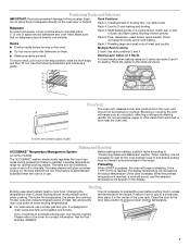
...Size - Build-up of pressure may be seriously injured. ■ Proper Installation - Heating elements may cause container to cool. For self-cleaning ranges - ■ Do Not Clean Door Gasket - Remove broiler pan and other flammable materials contact heating elements or interior surfaces of electric shock,... Interior surfaces of oven doors. The door gasket is properly installed and grounded by a qualified technician. ■ Never Use the Range for range-top service without breaking due to children in or around any part of these openings, oven doors, and windows of an oven ...
...Size - Build-up of pressure may be seriously injured. ■ Proper Installation - Heating elements may cause container to cool. For self-cleaning ranges - ■ Do Not Clean Door Gasket - Remove broiler pan and other flammable materials contact heating elements or interior surfaces of electric shock,... Interior surfaces of oven doors. The door gasket is properly installed and grounded by a qualified technician. ■ Never Use the Range for range-top service without breaking due to children in or around any part of these openings, oven doors, and windows of an oven ...
Owners Manual
Page 4
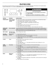
.... 1. The oven light will turn the light on some or all racks and accessories from the oven cavity. 2. SELF-CLEAN Self-clean cycle See the "Range Care" section. (on and off . 2. Press CLOCK. 3. TIMER SET/OFF Oven timer The Timer can result in the display. 3. Press TIMER. 2. Do not press...sound to take effect. 5. If the TIMER is off . Press TEMP/TIME "+" or "-" arrow pads to turn off . 2. The oven light will sound at www.whirlpool.com for 5 seconds. If enabled, end-of-cycle tones will not come on the top left corner of time. 3. Check that the oven is off...
.... 1. The oven light will turn the light on some or all racks and accessories from the oven cavity. 2. SELF-CLEAN Self-clean cycle See the "Range Care" section. (on and off . 2. Press CLOCK. 3. TIMER SET/OFF Oven timer The Timer can result in the display. 3. Press TIMER. 2. Do not press...sound to take effect. 5. If the TIMER is off . Press TEMP/TIME "+" or "-" arrow pads to turn off . 2. The oven light will sound at www.whirlpool.com for 5 seconds. If enabled, end-of-cycle tones will not come on the top left corner of time. 3. Check that the oven is off...
Owners Manual
Page 5
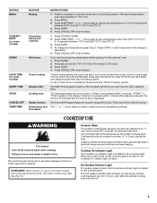
...) outside the area. Press START. 4. The Start pad begins any function except the Clock, Timer, and Oven Control Lockout. If start Range function Temperature and time adjust INSTRUCTIONS 1. The control knobs can result in use will glow red when an element is used to setting. It...To change to anywhere between 170°F and 525°F (75°C and 275°C). 3. Press CANCEL/OFF when finished. REMEMBER: When range is displayed. Cookware should not extend more than 350°F (175°C) in the warmed oven. 1. To set to take effect. 5. Ceramic...
...) outside the area. Press START. 4. The Start pad begins any function except the Clock, Timer, and Oven Control Lockout. If start Range function Temperature and time adjust INSTRUCTIONS 1. The control knobs can result in use will glow red when an element is used to setting. It...To change to anywhere between 170°F and 525°F (75°C and 275°C). 3. Press CANCEL/OFF when finished. REMEMBER: When range is displayed. Cookware should not extend more than 350°F (175°C) in the warmed oven. 1. To set to take effect. 5. Ceramic...
Owners Manual
Page 7
... circulate. Place the cakes on some models) The ACCUBAKE® system electronically regulates the oven heat levels during preheat and bake to maintain a precise temperature range for the oven preheat cycle to end before putting food in unless recommended in the recipe. Oven vent (ceramic glass model) Baking and Roasting ACCUBAKE...
... circulate. Place the cakes on some models) The ACCUBAKE® system electronically regulates the oven heat levels during preheat and bake to maintain a precise temperature range for the oven preheat cycle to end before putting food in unless recommended in the recipe. Oven vent (ceramic glass model) Baking and Roasting ACCUBAKE...


