
Installation Instructions
Page 2
DRYER SAFETY 2
DRYER SAFETY 2
Installation Instructions
Page 4
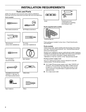
... Service" section of the "Use and Care Guide". Check that opens to the dryer must end in dryer drum. Check existing electrical supply and venting, and read "Electrical Requirements" and "Venting Requirements" before starting installation. The cord should contain: ■■ A UL listed 30-amp power supply cord, rated 120/240 volt minimum. The wires that connect to 1" (25 mm) or hex-head socket wrench Utility knife Leveling legs (4) Parts package is located in ring terminals or spade terminals...
... Service" section of the "Use and Care Guide". Check that opens to the dryer must end in dryer drum. Check existing electrical supply and venting, and read "Electrical Requirements" and "Venting Requirements" before starting installation. The cord should contain: ■■ A UL listed 30-amp power supply cord, rated 120/240 volt minimum. The wires that connect to 1" (25 mm) or hex-head socket wrench Utility knife Leveling legs (4) Parts package is located in ring terminals or spade terminals...
Installation Instructions
Page 5
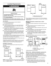
...], install Extended Dryer Feet Kit, Part Number 279810.) If not level, clothes may not tumble properly and automatic sensor cycles may not operate correctly. capacity washer). Recessed area B. Closet door with equivalent ventilation openings are acceptable. ■■ Companion appliance spacing should be considered for ease of installation and servicing. ■■ Additional clearances might not shut off at the end of 3.8 cu. The opening hamper door *Most installations require...
...], install Extended Dryer Feet Kit, Part Number 279810.) If not level, clothes may not tumble properly and automatic sensor cycles may not operate correctly. capacity washer). Recessed area B. Closet door with equivalent ventilation openings are acceptable. ■■ Companion appliance spacing should be considered for ease of installation and servicing. ■■ Additional clearances might not shut off at the end of 3.8 cu. The opening hamper door *Most installations require...
Installation Instructions
Page 6
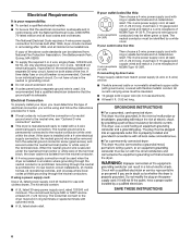
... solid copper wires and match a 3-wire receptacle of NEMA Type 10-30R. If connecting by a white cover. The National Electrical Code requires a 4-wire power supply connection for (1) new branch-circuit installations, (2) mobile homes, (3) recreational vehicles, and (4) areas where local codes prohibit grounding through the neutral conductor is prohibited. A time-delay fuse or circuit breaker is recommended. Grounding through the neutral is prohibited for homes built after 1996, dryer circuits involved...
... solid copper wires and match a 3-wire receptacle of NEMA Type 10-30R. If connecting by a white cover. The National Electrical Code requires a 4-wire power supply connection for (1) new branch-circuit installations, (2) mobile homes, (3) recreational vehicles, and (4) areas where local codes prohibit grounding through the neutral conductor is prohibited. A time-delay fuse or circuit breaker is recommended. Grounding through the neutral is prohibited for homes built after 1996, dryer circuits involved...

Installation Instructions
Page 7
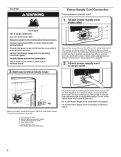
... power supply cord strain relief: then steps 3-5 for 4-wire Power Supply Cord Connection section. ft. Then go to Venting Requirements. 4-wire direct connection: Go to connect the exhaust vent. Prepare dryer for electrical connection and to steps 1-2 on page 11 for direct wire strain relief: then steps 3-7 for 4-wire Direct Wire Connection section. Leave enough room for leveling legs To avoid damaging floor, use a large flat piece of dryer. Then go to match height of dryer. capacity washer...
... power supply cord strain relief: then steps 3-5 for 4-wire Power Supply Cord Connection section. ft. Then go to Venting Requirements. 4-wire direct connection: Go to connect the exhaust vent. Prepare dryer for electrical connection and to steps 1-2 on page 11 for direct wire strain relief: then steps 3-7 for 4-wire Direct Wire Connection section. Leave enough room for leveling legs To avoid damaging floor, use a large flat piece of dryer. Then go to match height of dryer. capacity washer...
Installation Instructions
Page 8
... power supply cord strain relief A B C D Remove the screws from a 3/4" (19 mm) UL listed strain relief (UL marking on the power supply cord is pointing down (D), and hold the two clamp sections (C) together. 2. For 3-wire Power Supply Cord Connection, see page 9. Terminal block cover B. Direct Wire 2. A. Put the tabs of the two clamp sections (C) into the hole (B) below terminal block cover Put power supply cord through the strain relief. For 4 wire Power Supply Cord Connection...
... power supply cord strain relief A B C D Remove the screws from a 3/4" (19 mm) UL listed strain relief (UL marking on the power supply cord is pointing down (D), and hold the two clamp sections (C) together. 2. For 3-wire Power Supply Cord Connection, see page 9. Terminal block cover B. Direct Wire 2. A. Put the tabs of the two clamp sections (C) into the hole (B) below terminal block cover Put power supply cord through the strain relief. For 4 wire Power Supply Cord Connection...

Installation Instructions
Page 9
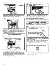
...) UL listed strain relief F. 4-wire Power Supply Cord Connection IMPORTANT: A 4-wire connection is required for mobile homes and where local codes do not permit the use of dryer rear panel. Ground prong D. Ring terminals 3. Connect remaining wires to connect neutral ground wire and neutral wire. Finally, reinsert tab of terminal block cover into slot of 3-wire connections. B D E A C GF A. 3-wire receptacle (NEMA type 10-30R) B. 3-wire plug C. Tighten screws. Remove center screw B Remove center terminal block screw (B). 9 Prepare to outer terminal block screws...
...) UL listed strain relief F. 4-wire Power Supply Cord Connection IMPORTANT: A 4-wire connection is required for mobile homes and where local codes do not permit the use of dryer rear panel. Ground prong D. Ring terminals 3. Connect remaining wires to connect neutral ground wire and neutral wire. Finally, reinsert tab of terminal block cover into slot of 3-wire connections. B D E A C GF A. 3-wire receptacle (NEMA type 10-30R) B. 3-wire plug C. Tighten screws. Remove center screw B Remove center terminal block screw (B). 9 Prepare to outer terminal block screws...
Installation Instructions
Page 10
... must have a tight fit with hold-down screw. For 3-wire Direct Wire Connection, see page 11. Strip 5" (127 mm) of outer covering from end of power supply cord to step 3 below the terminal block opening , screw the removable conduit connector onto the strain relief threads (C). Tighten strain relief screws. Secure cover with the dryer cabinet and be moved if needed. Finally, reinsert tab of terminal block cover into hooks. 4.
... must have a tight fit with hold-down screw. For 3-wire Direct Wire Connection, see page 11. Strip 5" (127 mm) of outer covering from end of power supply cord to step 3 below the terminal block opening , screw the removable conduit connector onto the strain relief threads (C). Tighten strain relief screws. Secure cover with the dryer cabinet and be moved if needed. Finally, reinsert tab of terminal block cover into hooks. 4.
Installation Instructions
Page 11
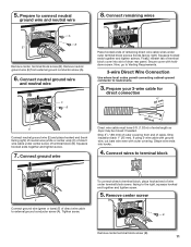
... wire) (C) of dryer rear panel. Connect wires to external ground conductor screw (A). Prepare to neutral wire. 3. Now, go to Venting Requirements. 3-wire Direct Wire Connection Use where local codes permit connecting cabinet-ground conductor to connect neutral ground wire and neutral wire 8. If using 3-wire cable with ground wire, cut bare wire even with holddown screw. Shape wire ends into slot of direct wire cable under outer terminal block screws (hooks facing right). Tighten screw. Connect ground wire Place hooked ends of remaining direct wire...
... wire) (C) of dryer rear panel. Connect wires to external ground conductor screw (A). Prepare to neutral wire. 3. Now, go to Venting Requirements. 3-wire Direct Wire Connection Use where local codes permit connecting cabinet-ground conductor to connect neutral ground wire and neutral wire 8. If using 3-wire cable with ground wire, cut bare wire even with holddown screw. Shape wire ends into slot of direct wire cable under outer terminal block screws (hooks facing right). Tighten screw. Connect ground wire Place hooked ends of remaining direct wire...

Installation Instructions
Page 12
Tighten screw. 7. Connect remaining wires E Connect neutral ground wire (E) and neutral wire (white or center wire) (C) of remaining wires under center terminal block screw (B). Place hooked ends of power supply cord or cable under outer terminal block screws (hooks facing right). Tighten screws. Prepare to Venting Requirements. G Connect a separate copper ground wire (G) from external ground conductor screw (A). Optional 3-wire Connection You must verify with holddown screw. Connect remaining wires Place hooked ends of dryer rear panel. Squeeze hooked ends together...
Tighten screw. 7. Connect remaining wires E Connect neutral ground wire (E) and neutral wire (white or center wire) (C) of remaining wires under center terminal block screw (B). Place hooked ends of power supply cord or cable under outer terminal block screws (hooks facing right). Tighten screws. Prepare to Venting Requirements. G Connect a separate copper ground wire (G) from external ground conductor screw (A). Optional 3-wire Connection You must verify with holddown screw. Connect remaining wires Place hooked ends of dryer rear panel. Squeeze hooked ends together...
Installation Instructions
Page 13
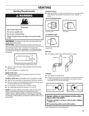
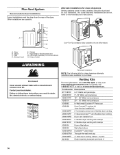
.... Review "Vent System Chart" and, if necessary, modify existing vent system to seal all governing codes and ordinances. Flexible metal vent: (Acceptable only if accessible to clean) ■■ Must be used . ■■ Do not use duct tape. Only rigid or flexible metal vent shall be fully extended and supported in final dryer location. ■■ Remove excess to avoid crushing and kinking. See "Venting Kits...
.... Review "Vent System Chart" and, if necessary, modify existing vent system to seal all governing codes and ordinances. Flexible metal vent: (Acceptable only if accessible to clean) ■■ Must be used . ■■ Do not use duct tape. Only rigid or flexible metal vent shall be fully extended and supported in final dryer location. ■■ Remove excess to avoid crushing and kinking. See "Venting Kits...
Installation Instructions
Page 14
... connect elbows H. A A. Plan Vent System Recommended exhaust installations Typical installations vent the dryer from the rear of the dryer. Two close-clearance installations are available for close clearance alternate installations are shown. Vent length necessary to the manufacturer's instructions. Dryer B. Elbow C. Rigid metal or flexible metal vent G. Select the type best for close elbow 4396007RW Through-the-wall vent cap 4396008RP 4" steel dryer venting clamps - 2 pack 8212662 Flush mounting louvered vent...
... connect elbows H. A A. Plan Vent System Recommended exhaust installations Typical installations vent the dryer from the rear of the dryer. Two close-clearance installations are available for close clearance alternate installations are shown. Vent length necessary to the manufacturer's instructions. Dryer B. Elbow C. Rigid metal or flexible metal vent G. Select the type best for close elbow 4396007RW Through-the-wall vent cap 4396008RP 4" steel dryer venting clamps - 2 pack 8212662 Flush mounting louvered vent...
Installation Instructions
Page 15
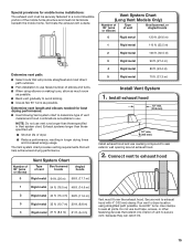
....7 m) 29 ft. (8.8 m) 4 Rigid metal 27 ft. (8.2 m) 21 ft. (6.4 m) Vent must not terminate beneath the mobile home. Do not use . Terminate the exhaust vent outside. Install exhaust hood 12" min. (305 mm) 12" min. (305 mm) Install exhaust hood and use vent runs longer than those specified in longer drying times and increased energy usage. Run vent to dryer location using elbows or making turns, allow as much room as possible. ■■...
....7 m) 29 ft. (8.8 m) 4 Rigid metal 27 ft. (8.2 m) 21 ft. (6.4 m) Vent must not terminate beneath the mobile home. Do not use . Terminate the exhaust vent outside. Install exhaust hood 12" min. (305 mm) 12" min. (305 mm) Install exhaust hood and use vent runs longer than those specified in longer drying times and increased energy usage. Run vent to dryer location using elbows or making turns, allow as much room as possible. ■■...
Installation Instructions
Page 16
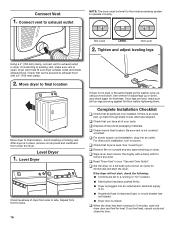
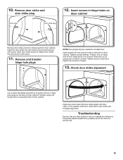
..., open the dryer door and feel heat, cancel cycle and close the door. If you have all packaging materials. Not Level LEVEL Not Level 2. Complete Installation Checklist q Check that vent is secured to exhaust hood with a damp cloth to adjust legs up using a wood block. Tighten and adjust leveling legs Using a 4" (102 mm) clamp, connect vent to side. If there is plugged into an outlet. For direct wire installation, turn on dryer. q Remove film...
..., open the dryer door and feel heat, cancel cycle and close the door. If you have all packaging materials. Not Level LEVEL Not Level 2. Complete Installation Checklist q Check that vent is secured to exhaust hood with a damp cloth to adjust legs up using a wood block. Tighten and adjust leveling legs Using a 4" (102 mm) clamp, connect vent to side. If there is plugged into an outlet. For direct wire installation, turn on dryer. q Remove film...
Installation Instructions
Page 17
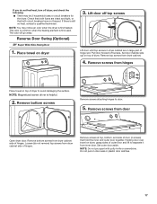
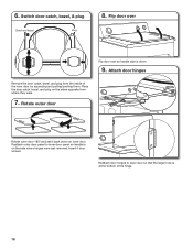
Check that both circuit breakers have not tripped. NOTE: You may be 2 household fuses or circuit breakers for the dryer. Place towel on door seal or plastic door catches. 17 Remove bottom screws Remove screws attaching hinges to separate it from inner door. Remove screws at top, bottom, and side of door (4 screws) that both fuses are in large part of hinge slot. If you do not...
Check that both circuit breakers have not tripped. NOTE: You may be 2 household fuses or circuit breakers for the dryer. Place towel on door seal or plastic door catches. 17 Remove bottom screws Remove screws attaching hinges to separate it from inner door. Remove screws at top, bottom, and side of door (4 screws) that both fuses are in large part of hinge slot. If you do not...
Installation Instructions
Page 18
... inner door. Attach door hinges Remove the door catch, bezel, and plug from where they were. 7. Reattach door hinges to inner door panel so handle is at the bottom of the inner door by squeezing and pulling/pushing them. Switch door catch, bezel, & plug Catch and bezel Plug 8. Place the door catch, bezel, and plug on the side where hinges were just removed. Reattach outer door panel to dryer door...
... inner door. Attach door hinges Remove the door catch, bezel, and plug from where they were. 7. Reattach door hinges to inner door panel so handle is at the bottom of the inner door by squeezing and pulling/pushing them. Switch door catch, bezel, & plug Catch and bezel Plug 8. Place the door catch, bezel, and plug on the side where hinges were just removed. Reattach outer door panel to dryer door...
Installation Instructions
Page 19
... are in hinges. 13. Check door strike alignment Use a small, flat-blade screwdriver to possibly avoid the cost of dryer cabinet. Troubleshooting See the Use and Care Guide or visit our website and reference Frequently Asked Questions to gently remove 4 hinge hole plugs on left or right within slot to reinstall door. 10. Insert the door strike into original door strike hole and secure...
... are in hinges. 13. Check door strike alignment Use a small, flat-blade screwdriver to possibly avoid the cost of dryer cabinet. Troubleshooting See the Use and Care Guide or visit our website and reference Frequently Asked Questions to gently remove 4 hinge hole plugs on left or right within slot to reinstall door. 10. Insert the door strike into original door strike hole and secure...

Installation Instructions
Page 20
W10562358A W10562359A-SP ®/™ ©2013. All rights reserved. 05/13 Printed in U.S.A.
W10562358A W10562359A-SP ®/™ ©2013. All rights reserved. 05/13 Printed in U.S.A.
Dimension Guide
Page 1
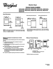
... might be required for the exhaust vent with a door, minimum ventilation openings in .2 * (155 cm )2 1" 29" 1" 1"* 27¾" (25 mm) (737 mm) (25 mm) (25 mm) (705 mm) A B C A. See "Venting Requirements." Side view - Louvered doors with vents *Additional spacing recommended 3"* (76 mm) 3"* (76 mm) W10562358A 05/2015 closet or confined area C. ft. Dryer Dimensions 29" (737 mm) 433/8" (1102 mm) Electric Dryer PRODUCT MODEL NUMBERS WED4800B...
... might be required for the exhaust vent with a door, minimum ventilation openings in .2 * (155 cm )2 1" 29" 1" 1"* 27¾" (25 mm) (737 mm) (25 mm) (25 mm) (705 mm) A B C A. See "Venting Requirements." Side view - Louvered doors with vents *Additional spacing recommended 3"* (76 mm) 3"* (76 mm) W10562358A 05/2015 closet or confined area C. ft. Dryer Dimensions 29" (737 mm) 433/8" (1102 mm) Electric Dryer PRODUCT MODEL NUMBERS WED4800B...
Dimension Guide
Page 2
... drying times and increased energy usage. Vent System Chart (Long Vent Models Only) Number of 90° turns or elbows Type of dryer. ■■ Reduce performance, resulting in Vent System Chart. A time-delay fuse or circuit breaker is required. Connect to avoid kinking. ■■ Use as few 90° turns as possible. Exhaust hood must be in the path of vent material and hood combinations acceptable to change without notice. Determine vent length...
... drying times and increased energy usage. Vent System Chart (Long Vent Models Only) Number of 90° turns or elbows Type of dryer. ■■ Reduce performance, resulting in Vent System Chart. A time-delay fuse or circuit breaker is required. Connect to avoid kinking. ■■ Use as few 90° turns as possible. Exhaust hood must be in the path of vent material and hood combinations acceptable to change without notice. Determine vent length...


