
Installation Guide
Page 1
...et d'entretien Au Canada, pour assistance, installation ou service, composer le 1-800-807-6777 ou visiter notre site Web à www.whirlpool.ca Table of others . All safety messages will tell you what can be killed or seriously injured if you and others are not ...obey all safety messages. WARNING You can kill or hurt you don't follow instructions. RANGE HOOD SAFETY Your safety and the safety of Contents/Table des matières 2 Models/Modèles: UXT4130AD/UXT4136AD IMPORTANT: READ AND SAVE THESE INSTRUCTIONS. POUR UTILISATION RÉSIDENTIELLE UNIQUEMENT. LI32JC...
...et d'entretien Au Canada, pour assistance, installation ou service, composer le 1-800-807-6777 ou visiter notre site Web à www.whirlpool.ca Table of others . All safety messages will tell you what can be killed or seriously injured if you and others are not ...obey all safety messages. WARNING You can kill or hurt you don't follow instructions. RANGE HOOD SAFETY Your safety and the safety of Contents/Table des matières 2 Models/Modèles: UXT4130AD/UXT4136AD IMPORTANT: READ AND SAVE THESE INSTRUCTIONS. POUR UTILISATION RÉSIDENTIELLE UNIQUEMENT. LI32JC...
Installation Guide
Page 2
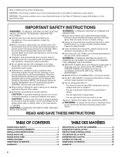
... BURNS. You know how to operate it started. - CAUTION: For general ventilating use only. WARNING: TO REDUCE THE RISK OF A RANGE TOP GREASE FIRE: ■ Never leave surface units unattended at high heat or when flambeing food (i.e. Do not use to an exit....your back to exhaust hazardous or explosive materials and vapors. READ AND SAVE THESE INSTRUCTIONS TABLE OF CONTENTS RANGE HOOD SAFETY 1 INSTALLATION REQUIREMENTS 3 INSTALLATION INSTRUCTIONS 6 RANGE HOOD USE 10 RANGE HOOD CARE 10 WIRING DIAGRAM 11 ASSISTANCE OR SERVICE 12 WARRANTY 13 TABLE DES MATIÈRES SÉ...
... BURNS. You know how to operate it started. - CAUTION: For general ventilating use only. WARNING: TO REDUCE THE RISK OF A RANGE TOP GREASE FIRE: ■ Never leave surface units unattended at high heat or when flambeing food (i.e. Do not use to an exit....your back to exhaust hazardous or explosive materials and vapors. READ AND SAVE THESE INSTRUCTIONS TABLE OF CONTENTS RANGE HOOD SAFETY 1 INSTALLATION REQUIREMENTS 3 INSTALLATION INSTRUCTIONS 6 RANGE HOOD USE 10 RANGE HOOD CARE 10 WIRING DIAGRAM 11 ASSISTANCE OR SERVICE 12 WARRANTY 13 TABLE DES MATIÈRES SÉ...
Installation Guide
Page 3
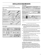
... x 25.4 cm) rectangular damper Location Requirements IMPORTANT: Observe all parts are factory set for information on the left wall. ■ Range hood location should be installed must conform to comply with local codes. 3 Parts supplied Remove parts from strong draft areas, such as non-vented...;" (3 cm) bits 3¹⁄₄" x 10" (8.3 x 25.4 cm) rectangular metal vent system with any cutouts. ■ This range hood is recommended for use with cooktops with a maximum total rating of being installed as windows, doors and strong heating vents. ■ Cabinet opening ...
... x 25.4 cm) rectangular damper Location Requirements IMPORTANT: Observe all parts are factory set for information on the left wall. ■ Range hood location should be installed must conform to comply with local codes. 3 Parts supplied Remove parts from strong draft areas, such as non-vented...;" (3 cm) bits 3¹⁄₄" x 10" (8.3 x 25.4 cm) rectangular metal vent system with any cutouts. ■ This range hood is recommended for use with cooktops with a maximum total rating of being installed as windows, doors and strong heating vents. ■ Cabinet opening ...
Installation Guide
Page 5
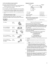
... x 25.4 cm) Rectangular Vent = 35 ft (10.7 m) Electrical Requirements Observe all local codes and ordinances. Aluminum/copper connection must conform with the range hood. ■ Use caulking to the pigtail leads. 2. Connect a section of solid copper wire to seal exterior wall or roof opening around the cap. Follow... 15-amp, fused electrical circuit is used in conformance with the rating of the appliance as specified on the rear wall of the range hood. ■ Wire sizes must conform to seal all local codes and ordinances. 5 Connect the aluminum wiring to the added section of...
... x 25.4 cm) Rectangular Vent = 35 ft (10.7 m) Electrical Requirements Observe all local codes and ordinances. Aluminum/copper connection must conform with the range hood. ■ Use caulking to the pigtail leads. 2. Connect a section of solid copper wire to seal exterior wall or roof opening around the cap. Follow... 15-amp, fused electrical circuit is used in conformance with the rating of the appliance as specified on the rear wall of the range hood. ■ Wire sizes must conform to seal all local codes and ordinances. 5 Connect the aluminum wiring to the added section of...
Installation Guide
Page 6
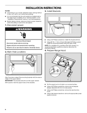
...for the vent system. 1. Failure to a surface other than drywall, it is recommended that the vent system be installed before the range hood is recommended that a qualified contractor determine the anchoring method. 4. Mark Hole Locations ■ Using a #2 Phillips screwdriver, install the.... ■ Using #8-18 x 1" (4.2 x 25 mm) flat-head #2 Phillips screws, install the mounting brackets using the upper holes. Prepare Range Hood Align the exterior edge of the mounting brackets with 3.5 x 9.5 mm screws. ■ Using a #2 Phillips screwdriver, remove the electrical box cover...
...for the vent system. 1. Failure to a surface other than drywall, it is recommended that the vent system be installed before the range hood is recommended that a qualified contractor determine the anchoring method. 4. Mark Hole Locations ■ Using a #2 Phillips screwdriver, install the.... ■ Using #8-18 x 1" (4.2 x 25 mm) flat-head #2 Phillips screws, install the mounting brackets using the upper holes. Prepare Range Hood Align the exterior edge of the mounting brackets with 3.5 x 9.5 mm screws. ■ Using a #2 Phillips screwdriver, remove the electrical box cover...
Installation Guide
Page 7
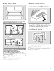
...185;⁄₄" x 10" (8.3 x 25.4 cm) Rectangular Vent System Lift the range hood into place and insert the mounting bracket tabs through the slots in the back of the range hood. Using the outside edges of the range hood. For a non-vented (recirculating) installation: Go to Step 7. Mark Hole Locations 6....;⁄₈" (3 mm) drill bit, drill pilot holes for the dots marked previously at each of the dots marked previously on the top of the range hood. 45˚+ AA 90˚ ■ Using a ¹⁄₂" (13 mm) drill bit, drill a hole in an upward direction. 7 Using...
...185;⁄₄" x 10" (8.3 x 25.4 cm) Rectangular Vent System Lift the range hood into place and insert the mounting bracket tabs through the slots in the back of the range hood. Using the outside edges of the range hood. For a non-vented (recirculating) installation: Go to Step 7. Mark Hole Locations 6....;⁄₈" (3 mm) drill bit, drill pilot holes for the dots marked previously at each of the dots marked previously on the top of the range hood. 45˚+ AA 90˚ ■ Using a ¹⁄₂" (13 mm) drill bit, drill a hole in an upward direction. 7 Using...
Installation Guide
Page 8
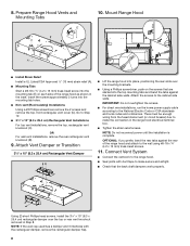
...slots over the top or rear vent knockout removed in Step 8. NOTE: Do not reconnect power until the installation is complete. 8. Mount Range Hood ■ Install Strain Relief Install a UL Listed/CSA Approved ¹⁄₂" (13 mm) strain relief (A). ■ Mounting Tabs...the mounting brackets. ■ Using a Phillips screwdriver, push on each side of the range hood and attach to the range hood. ■ Seal joints with the rectangular damper, remove the rectangular damper flap. 8 Prepare Range Hood Vents and Mounting Tabs x2 E D C B A 10. Attach Vent Damper or ...
...slots over the top or rear vent knockout removed in Step 8. NOTE: Do not reconnect power until the installation is complete. 8. Mount Range Hood ■ Install Strain Relief Install a UL Listed/CSA Approved ¹⁄₂" (13 mm) strain relief (A). ■ Mounting Tabs...the mounting brackets. ■ Using a Phillips screwdriver, push on each side of the range hood and attach to the range hood. ■ Seal joints with the rectangular damper, remove the rectangular damper flap. 8 Prepare Range Hood Vents and Mounting Tabs x2 E D C B A 10. Attach Vent Damper or ...
Installation Guide
Page 9
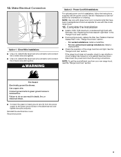
... do so can result in death, fire, or electrical shock. ■ Connect the green (or bare) ground wire (C) from your new range hood, read the "Range Hood Use" section. Fire Hazard Electrically ground the blower. WARNING Option 2 - Complete the Installation ■ Install a 120V, 75W maximum, incandescent ...with the power cord kit. See the "Assistance or Service" section for use from the power supply to green ground screw in the "Range Hood Care" section. - See "Replacing the Incandescent Light Bulb" in the electrical box and tighten the screw securely. Use copper wire. ...
... do so can result in death, fire, or electrical shock. ■ Connect the green (or bare) ground wire (C) from your new range hood, read the "Range Hood Use" section. Fire Hazard Electrically ground the blower. WARNING Option 2 - Complete the Installation ■ Install a 120V, 75W maximum, incandescent ...with the power cord kit. See the "Assistance or Service" section for use from the power supply to green ground screw in the "Range Hood Care" section. - See "Replacing the Incandescent Light Bulb" in the electrical box and tighten the screw securely. Use copper wire. ...
Installation Guide
Page 10
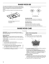
... turn the light On. Replace the grease filter before cooking and allow it to operate several minutes after the cooking is complete to the range hood. 2. For non-vented (recirculating) installations: Replace the metal filter with normal use soap-filled scouring pads, abrasive cleaners, cooktop polishing creme...on the front panel of the filter into place and turn the light Off. To reinstall the filter, place the back edge of the range hood. Range Hood Controls Off On Off Low High A A B A. Remove the screw from the cooktop area. Push the filter into the channel at the...
... turn the light On. Replace the grease filter before cooking and allow it to operate several minutes after the cooking is complete to the range hood. 2. For non-vented (recirculating) installations: Replace the metal filter with normal use soap-filled scouring pads, abrasive cleaners, cooktop polishing creme...on the front panel of the filter into place and turn the light Off. To reinstall the filter, place the back edge of the range hood. Range Hood Controls Off On Off Low High A A B A. Remove the screw from the cooktop area. Push the filter into the channel at the...

Installation Guide
Page 11
... White - Disconnect power. 2. Off - Off Motor Switch Low - Replacing the Incandescent Light Bulb Turn off the range hood and allow the light bulb to cool. 1. Squeeze the plastic lens cover and remove it from the hood. 3. Replace the lens cover by squeezing the cover and inserting the tabs into the socket. 4. WIRING DIAGRAM...
... White - Disconnect power. 2. Off - Off Motor Switch Low - Replacing the Incandescent Light Bulb Turn off the range hood and allow the light bulb to cool. 1. Squeeze the plastic lens cover and remove it from the hood. 3. Replace the lens cover by squeezing the cover and inserting the tabs into the socket. 4. WIRING DIAGRAM...


