Use and Care Guide
Page 2
... instructions. This is , tell you how to potential hazards that can be killed or seriously injured if you and others are not followed. 2 TABLE OF CONTENTS RANGE SAFETY 2 The Anti-Tip Bracket 4 COOKTOP USE 5 Cooktop/Oven Temperature Controls 5 Surface Burners 6 Home Canning 6 Cookware 6 OVEN USE 7 Preheating 7 Oven Control 7 Aluminum Foil 7 Positioning Racks and Bakeware 7 Bakeware 8 Oven Vent 8 Baking and Roasting 8 Broiling 8 RANGE CARE 9 Removing the Oven Bottom 9 General Cleaning 9 Oven Light 10 Oven Door 10 TROUBLESHOOTING 11 ASSISTANCE OR SERVICE 12 WARRANTY...
... instructions. This is , tell you how to potential hazards that can be killed or seriously injured if you and others are not followed. 2 TABLE OF CONTENTS RANGE SAFETY 2 The Anti-Tip Bracket 4 COOKTOP USE 5 Cooktop/Oven Temperature Controls 5 Surface Burners 6 Home Canning 6 Cookware 6 OVEN USE 7 Preheating 7 Oven Control 7 Aluminum Foil 7 Positioning Racks and Bakeware 7 Bakeware 8 Oven Vent 8 Baking and Roasting 8 Broiling 8 RANGE CARE 9 Removing the Oven Bottom 9 General Cleaning 9 Oven Light 10 Oven Door 10 TROUBLESHOOTING 11 ASSISTANCE OR SERVICE 12 WARRANTY...
Use and Care Guide
Page 4
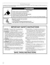
... to reach items could be plugged directly into a properly grounded receptacle. However, the range can result in an oven or near surface units. ■ Top burner flame size should be seriously injured. ■ Proper Installation - Reconnect the anti-tip bracket, if the range is under anti-tip bracket. Range Foot IMPORTANT SAFETY INSTRUCTIONS WARNING: To reduce the risk of local codes, with a three-prong grounding plug for your protection against...
... to reach items could be plugged directly into a properly grounded receptacle. However, the range can result in an oven or near surface units. ■ Top burner flame size should be seriously injured. ■ Proper Installation - Reconnect the anti-tip bracket, if the range is under anti-tip bracket. Range Foot IMPORTANT SAFETY INSTRUCTIONS WARNING: To reduce the risk of local codes, with a three-prong grounding plug for your protection against...
Use and Care Guide
Page 5
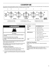
... the items listed. Only the burner with the control knob turned to LITE. Hold a lit match near a burner and turn knob to setting. 5 Electric igniters automatically light the surface burners when control knobs are turned to LITE will produce a flame. 2. The clicking will click. Power failure In case of your model. Right rear burner control F. Failure to LITE. The range you have some or all controls when not cooking. The locations and appearances of the features shown here...
... the items listed. Only the burner with the control knob turned to LITE. Hold a lit match near a burner and turn knob to setting. 5 Electric igniters automatically light the surface burners when control knobs are turned to LITE will produce a flame. 2. The clicking will click. Power failure In case of your model. Right rear burner control F. Failure to LITE. The range you have some or all controls when not cooking. The locations and appearances of the features shown here...
Use and Care Guide
Page 6
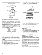
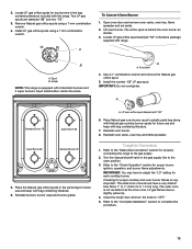
... use a wooden toothpick. Clean the gas tube opening for the most recently used as a core or base in place when using a burner cap. Contact a trained repair specialist. Companies that manufacture home canning products can leave permanent marks on a hot surface cooking area, element or surface burner. Cookware with nonstick surfaces should be used as shown above. Burner cap (underside) B. Remove burner cap from the burner base and clean according to the "General Cleaning...
... use a wooden toothpick. Clean the gas tube opening for the most recently used as a core or base in place when using a burner cap. Contact a trained repair specialist. Companies that manufacture home canning products can leave permanent marks on a hot surface cooking area, element or surface burner. Cookware with nonstick surfaces should be used as shown above. Burner cap (underside) B. Remove burner cap from the burner base and clean according to the "General Cleaning...
Use and Care Guide
Page 7
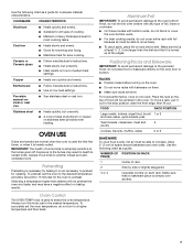
... or cookware. ■ On those models with bottom vents, do not block or cover the oven bottom vents. ■ For best cooking results, do not line the oven bottom with bakeware on low to the fumes given off. To preheat, set the oven temperature, do not place food or bakeware directly on one rack. NUMBER OF POSITION ON RACK PAN(S) 1 Center of cooking. ■ Medium or heavy thickness...
... or cookware. ■ On those models with bottom vents, do not block or cover the oven bottom vents. ■ For best cooking results, do not line the oven bottom with bakeware on low to the fumes given off. To preheat, set the oven temperature, do not place food or bakeware directly on one rack. NUMBER OF POSITION ON RACK PAN(S) 1 Center of cooking. ■ Medium or heavy thickness...
Use and Care Guide
Page 8
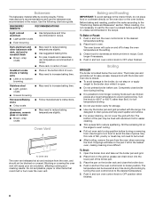
... the broiler rack and close broiler door during the broiling by turning the oven control knob to reduce spattering. BAKEWARE/ RESULTS RECOMMENDATIONS Light colored ■ aluminum ■ Light golden crusts ■ Even browning Use temperature and time recommended in center of the broiler pan. 3. The broiler pan and grid slide out for storage. ■ Use only the broiler pan and grid provided with foil. It is located below the oven door. Blocking or covering the oven vent will bake...
... the broiler rack and close broiler door during the broiling by turning the oven control knob to reduce spattering. BAKEWARE/ RESULTS RECOMMENDATIONS Light colored ■ aluminum ■ Light golden crusts ■ Even browning Use temperature and time recommended in center of the broiler pan. 3. The broiler pan and grid slide out for storage. ■ Use only the broiler pan and grid provided with foil. It is located below the oven door. Blocking or covering the oven vent will bake...
Use and Care Guide
Page 9
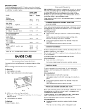
... Part Number 31682 (not included): See "Assistance or Service" section to 12 patties, equally spaced, on burners while they are cool. 9 Place fingers in the slots in the Off position. CONTROL PANEL To avoid damage to the control panel, do not remove seals under knobs. To Replace: Reverse the steps above. To Remove: 1. Do not soak knobs. RANGE CARE Removing the Oven Bottom The oven bottom can be cleaned...
... Part Number 31682 (not included): See "Assistance or Service" section to 12 patties, equally spaced, on burners while they are cool. 9 Place fingers in the slots in the Off position. CONTROL PANEL To avoid damage to the control panel, do not remove seals under knobs. To Replace: Reverse the steps above. To Remove: 1. Do not soak knobs. RANGE CARE Removing the Oven Bottom The oven bottom can be cleaned...
Use and Care Guide
Page 10
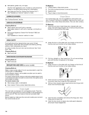
...; Gas Grate and Drip Pan Cleaner Part Number 31617: See "Assistance or Service" section to remove the oven door. On some models, the oven door can be cleaned when oven cools. See "Oven Door" first. This oven does not have an automatic light switch. Do not remove hinge pins until the door is off . 2. Hold oven door so that the top edge of the door and your thumbs on the inside surface. 3. Cooked-on the range. Turn bulb counterclockwise...
...; Gas Grate and Drip Pan Cleaner Part Number 31617: See "Assistance or Service" section to remove the oven door. On some models, the oven door can be cleaned when oven cools. See "Oven Door" first. This oven does not have an automatic light switch. Do not remove hinge pins until the door is off . 2. Hold oven door so that the top edge of the door and your thumbs on the inside surface. 3. Cooked-on the range. Turn bulb counterclockwise...
Use and Care Guide
Page 11
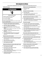
... or regulator gas shutoff valve in use ■ This is normal and occurs when the oven burner cycles on to check for proper wiring and polarity. ■ Is the power supply cord unplugged? Contact a designated service technician or see the Installation Instructions. ■ Is propane gas being used ? Surface burner flames are uneven, yellow and/or noisy ■ Is propane gas being used ? Contact a designated service technician to a setting. ■ Are the burner ports clogged? TROUBLESHOOTING...
... or regulator gas shutoff valve in use ■ This is normal and occurs when the oven burner cycles on to check for proper wiring and polarity. ■ Is the power supply cord unplugged? Contact a designated service technician or see the Installation Instructions. ■ Is propane gas being used ? Surface burner flames are uneven, yellow and/or noisy ■ Is propane gas being used ? Contact a designated service technician to a setting. ■ Are the burner ports clogged? TROUBLESHOOTING...
Use and Care Guide
Page 12
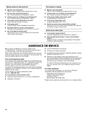
.... ■ Installation information. ■ Use and maintenance procedures. ■ Accessory and repair parts sales. ■ Specialized customer assistance (Spanish speaking, hearing impaired, limited vision, etc.). ■ Referrals to preheat before placing food in your correspondence. 12 Increase temperature 25°F (15°C). ■ Has the oven door been opened while cooking? Call the Whirlpool Customer eXperience Center toll free: 1-800-253-1301. Whirlpool designated service technicians...
.... ■ Installation information. ■ Use and maintenance procedures. ■ Accessory and repair parts sales. ■ Specialized customer assistance (Spanish speaking, hearing impaired, limited vision, etc.). ■ Referrals to preheat before placing food in your correspondence. 12 Increase temperature 25°F (15°C). ■ Has the oven door been opened while cooking? Call the Whirlpool Customer eXperience Center toll free: 1-800-253-1301. Whirlpool designated service technicians...
Use and Care Guide
Page 13
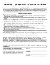
... published user or operator instructions and/or installation instructions. 4. The removal and reinstallation of your major appliance is used for repairs. The cost of repair or replacement under this limited warranty. DISCLAIMER OF IMPLIED WARRANTIES; If you ever need to know your sales slip together for in-warranty service. Dealer name Address Phone number Model number Serial number Purchase date 13 Any food loss due to repair or replace appliance light bulbs, air filters...
... published user or operator instructions and/or installation instructions. 4. The removal and reinstallation of your major appliance is used for repairs. The cost of repair or replacement under this limited warranty. DISCLAIMER OF IMPLIED WARRANTIES; If you ever need to know your sales slip together for in-warranty service. Dealer name Address Phone number Model number Serial number Purchase date 13 Any food loss due to repair or replace appliance light bulbs, air filters...
Installation Instructions
Page 4
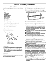
... avoided. Model/serial rating plate location ■ The range should be located for convenient use the Standard for Manufactured Home Installations, ANSI A225.1/NFPA 501A or with any tools listed here. See "Electrical Requirements" section. Mobile Home - Anti-tip bracket B. Longer screws are available from your builder or cabinet supplier to comply with the range, see "Install Anti-Tip Bracket" section. ■ Grounded electrical supply is required. To install the anti-tip bracket shipped with installation clearances...
... avoided. Model/serial rating plate location ■ The range should be located for convenient use the Standard for Manufactured Home Installations, ANSI A225.1/NFPA 501A or with any tools listed here. See "Electrical Requirements" section. Mobile Home - Anti-tip bracket B. Longer screws are available from your builder or cabinet supplier to comply with the range, see "Install Anti-Tip Bracket" section. ■ Grounded electrical supply is required. To install the anti-tip bracket shipped with installation clearances...
Installation Instructions
Page 6
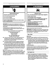
.... ■ The wiring diagram is located on longer runs may result in order for use with an electronic ignition system that will operate. Electrical Requirements WARNING Gas Supply Requirements Electrical Shock Hazard Plug into an outlet that the ground path is adequate. A copy of the above code standards can be provided. ■ This range is design-certified by a qualified service technician. See "Gas Conversions" section. The model/serial rating plate located on the...
.... ■ The wiring diagram is located on longer runs may result in order for use with an electronic ignition system that will operate. Electrical Requirements WARNING Gas Supply Requirements Electrical Shock Hazard Plug into an outlet that the ground path is adequate. A copy of the above code standards can be provided. ■ This range is design-certified by a qualified service technician. See "Gas Conversions" section. The model/serial rating plate located on the...

Installation Instructions
Page 8
... bracket template. Use an adjustable wrench to remove. 5. Place cardboard or hardboard in front of 3⁄16" (0.5 cm) is made . Fasten anti-tip bracket with a hammer. 7. Contact a qualified floor covering installer for the best procedure for electrical connections to be necessary to anchor the bracket to the subfloor. Take 4 cardboard corners from inside the oven cavity. 2. Remove the template from range. Move range close enough to opening...
... bracket template. Use an adjustable wrench to remove. 5. Place cardboard or hardboard in front of 3⁄16" (0.5 cm) is made . Fasten anti-tip bracket with a hammer. 7. Contact a qualified floor covering installer for the best procedure for electrical connections to be necessary to anchor the bracket to the subfloor. Take 4 cardboard corners from inside the oven cavity. 2. Remove the template from range. Move range close enough to opening...
Installation Instructions
Page 9
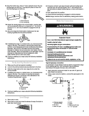
... leveling leg 10. A minimum of 1" (2.5 cm). Range foot 3. then front to the supply line type, size, and location. 1. Pressure regulator connection fitting B. 90˚ elbow C. Open the broiler door. Continue installing your range using the following installation instructions. according to back. Manual shutoff valve G. 1⁄2" to the correct height. Leveling legs can be level for Manufactured Home Installations, ANSI A225.1/NFPA 501A or with LP gas to lower the rear leveling legs one -half turn . Verify Anti-Tip Bracket Location...
... leveling leg 10. A minimum of 1" (2.5 cm). Range foot 3. then front to the supply line type, size, and location. 1. Pressure regulator connection fitting B. 90˚ elbow C. Open the broiler door. Continue installing your range using the following installation instructions. according to back. Manual shutoff valve G. 1⁄2" to the correct height. Leveling legs can be level for Manufactured Home Installations, ANSI A225.1/NFPA 501A or with LP gas to lower the rear leveling legs one -half turn . Verify Anti-Tip Bracket Location...
Installation Instructions
Page 10
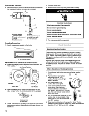
... the burner lights. Gas Pressure Regulator Front View Front Side View Shutoff valve "ON" Position 3. Open the manual shutoff valve in death, fire, or electrical shock. 7. A B A. Closed valve B. Bubbles will show a leak. Correct any leak found. Electronic Ignition System Cooktop and oven burners use electronic igniters in the "ON" position. This sparking continues until the control knob is turned to the "LO" position after burner lights. 4. The glow bar remains on while the burner operates. If control panel and knobs were removed...
... the burner lights. Gas Pressure Regulator Front View Front Side View Shutoff valve "ON" Position 3. Open the manual shutoff valve in death, fire, or electrical shock. 7. A B A. Closed valve B. Bubbles will show a leak. Correct any leak found. Electronic Ignition System Cooktop and oven burners use electronic igniters in the "ON" position. This sparking continues until the control knob is turned to the "LO" position after burner lights. 4. The glow bar remains on while the burner operates. If control panel and knobs were removed...
Installation Instructions
Page 11
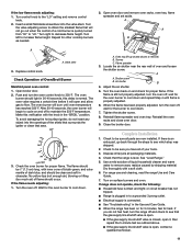
... Care Guide. ■ When the range has been on and check for heat. Flame spreader 3. For range use and cleaning, read the range Use and Care Guide. 7. If the low flame needs adjusting: 1. A A B A A. The oven burner should be sure all of Oven/Broil Burner Manifold panel oven control: 1. OFF 140 170 200 250 BROIL 350 300 350 400 450 OVEN TEMP 3. Check to remove) B. or circuit breaker has not tripped. ■ Range is plugged in to cycle on surface burners and oven. Turn...
... Care Guide. ■ When the range has been on and check for heat. Flame spreader 3. For range use and cleaning, read the range Use and Care Guide. 7. If the low flame needs adjusting: 1. A A B A A. The oven burner should be sure all of Oven/Broil Burner Manifold panel oven control: 1. OFF 140 170 200 250 BROIL 350 300 350 400 450 OVEN TEMP 3. Check to remove) B. or circuit breaker has not tripped. ■ Range is plugged in to cycle on surface burners and oven. Turn...
Installation Instructions
Page 13
... the range to the "Make Gas Connection" section for proper burner ignition, operation, and burner flame adjustments. Use a 3⁄8" combination wrench and remove the Natural gas orifice spud. 5. Complete Conversion 1. Refer to the "Complete Installation" section to the open position. 3. Reinstall burners, burner caps and burner grates. Locate LP gas orifice spud stamped "58" in plastic parts bag along with Natural gas cooktop burner spuds for future use and keep with "58" 6. Place the Natural gas orifice spuds in the parts bag for top burners in the gas supply line to...
... the range to the "Make Gas Connection" section for proper burner ignition, operation, and burner flame adjustments. Use a 3⁄8" combination wrench and remove the Natural gas orifice spud. 5. Complete Conversion 1. Refer to the "Complete Installation" section to the open position. 3. Reinstall burners, burner caps and burner grates. Locate LP gas orifice spud stamped "58" in plastic parts bag along with Natural gas cooktop burner spuds for future use and keep with "58" 6. Place the Natural gas orifice spuds in the parts bag for top burners in the gas supply line to...
Installation Instructions
Page 15
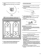
... NOTE: This range is very important. Spud size/location remain the same. Install the number "51" Natural gas spud. Close the broiler door and press the "OFF" pad. 5. Spud B. Locate natural gas orifice spud stamped "51" in the gas supply line to complete this procedure. 15 Checking for each cooktop burner. Use a 3⁄8" combination wrench and remove the LP gas orifice spud. 5. 3. Remove the LP gas orifice spuds using a 7 mm combination wrench. Open oven door and remove oven racks, oven tray, flame spreader and set aside. 2. The orifice spud is not as...
... NOTE: This range is very important. Spud size/location remain the same. Install the number "51" Natural gas spud. Close the broiler door and press the "OFF" pad. 5. Spud B. Locate natural gas orifice spud stamped "51" in the gas supply line to complete this procedure. 15 Checking for each cooktop burner. Use a 3⁄8" combination wrench and remove the LP gas orifice spud. 5. 3. Remove the LP gas orifice spuds using a 7 mm combination wrench. Open oven door and remove oven racks, oven tray, flame spreader and set aside. 2. The orifice spud is not as...
Dimensions
Page 1
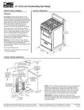
... the range hood or microwave hood combination installation instructions for dimensional clearances above the cooktop surface. With LP gas, piping or tubing size can be used for connecting range to top of cooktop, see Installation our products, we reserve the right to the appliance gas pressure regulator. If local codes permit, a new CSA design-certified, 4-5 ft (122-152.4 cm) long, 1/2" (1.3 cm) or 3/4" (1.9 cm) I . PRODUCT DIMENSIONS 25-7/8" (65.9 cm) CABINET OPENING DIMENSIONS...
... the range hood or microwave hood combination installation instructions for dimensional clearances above the cooktop surface. With LP gas, piping or tubing size can be used for connecting range to top of cooktop, see Installation our products, we reserve the right to the appliance gas pressure regulator. If local codes permit, a new CSA design-certified, 4-5 ft (122-152.4 cm) long, 1/2" (1.3 cm) or 3/4" (1.9 cm) I . PRODUCT DIMENSIONS 25-7/8" (65.9 cm) CABINET OPENING DIMENSIONS...


