
Dimension Guide
Page 1
... steel, 0.024" (0.6 mm) aluminum or 0.020" (0.5 mm) copper. 30" (76.2 cm) min. Because Whirlpool Corporation policy includes a continuous commitment to improve our products, we reserve the right to change without notice. Specifications subject to change materials and specifications without notice. 30" (76 cm) Freestanding Electric Range PRODUCT MODEL NUMBERS GFE461LV GFE471LV WFE301LV WFE361LV WFE364LV WFE366LV...
... steel, 0.024" (0.6 mm) aluminum or 0.020" (0.5 mm) copper. 30" (76.2 cm) min. Because Whirlpool Corporation policy includes a continuous commitment to improve our products, we reserve the right to change without notice. Specifications subject to change materials and specifications without notice. 30" (76 cm) Freestanding Electric Range PRODUCT MODEL NUMBERS GFE461LV GFE471LV WFE301LV WFE361LV WFE364LV WFE366LV...

Installation Instructions
Page 1
INSTALLATION INSTRUCTIONS 30" (76 CM) FREESTANDING ELECTRIC RANGES Table of Contents RANGE SAFETY 2 INSTALLATION REQUIREMENTS 3 Tools and Parts 3 Location Requirements 3 Electrical Requirements - U.S.A. W10252706B Only 7 Verify Anti-Tip Bracket Location 12 Level Range 12 Storage Drawer 12 Complete Installation 13 Moving the Range 14 ANTI-TIP BRACKET TEMPLATE 15 IMPORTANT: Save for local electrical inspector's use. Only 4 INSTALLATION INSTRUCTIONS 6 Unpack Range 6 Install Anti-Tip Bracket 6 Electrical Connection - U.S.A.
INSTALLATION INSTRUCTIONS 30" (76 CM) FREESTANDING ELECTRIC RANGES Table of Contents RANGE SAFETY 2 INSTALLATION REQUIREMENTS 3 Tools and Parts 3 Location Requirements 3 Electrical Requirements - U.S.A. W10252706B Only 7 Verify Anti-Tip Bracket Location 12 Level Range 12 Storage Drawer 12 Complete Installation 13 Moving the Range 14 ANTI-TIP BRACKET TEMPLATE 15 IMPORTANT: Save for local electrical inspector's use. Only 4 INSTALLATION INSTRUCTIONS 6 Unpack Range 6 Install Anti-Tip Bracket 6 Electrical Connection - U.S.A.

Installation Instructions
Page 2
... symbol alerts you to children and adults. 2 This is moved. Connect anti-tip bracket to follow instructions. Reconnect the anti-tip bracket, if the range is the safety alert symbol. All safety messages will follow instructions. WARNING You can be killed or seriously injured if you and others are not... be killed or seriously injured if you what can happen if the instructions are very important. Failure to rear range foot. RANGE SAFETY Your safety and the safety of injury, and tell you don't immediately follow these instructions can result in this manual and on ...
... symbol alerts you to children and adults. 2 This is moved. Connect anti-tip bracket to follow instructions. Reconnect the anti-tip bracket, if the range is the safety alert symbol. All safety messages will follow instructions. WARNING You can be killed or seriously injured if you and others are not... be killed or seriously injured if you what can happen if the instructions are very important. Failure to rear range foot. RANGE SAFETY Your safety and the safety of injury, and tell you don't immediately follow these instructions can result in this manual and on ...

Installation Instructions
Page 3
...used will not discolor, delaminate or sustain other damage. Check local codes. Mobile home installations require: ■ When this range must be revised. See "Electrical Connection" section. 3 Anti-tip bracket B. It is marked for convenient use with any tools listed here. Tools needed...nuts (attached to be provided, the risk can be reduced by installing a range hood that projects horizontally a minimum of 5" (12.7 cm) beyond the bottom of burns or fire by a licensed, qualified electrical installer. To install the antitip bracket shipped with the maximum allowable wood cabinet ...
...used will not discolor, delaminate or sustain other damage. Check local codes. Mobile home installations require: ■ When this range must be revised. See "Electrical Connection" section. 3 Anti-tip bracket B. It is marked for convenient use with any tools listed here. Tools needed...nuts (attached to be provided, the risk can be reduced by installing a range hood that projects horizontally a minimum of 5" (12.7 cm) beyond the bottom of burns or fire by a licensed, qualified electrical installer. To install the antitip bracket shipped with the maximum allowable wood cabinet ...

Installation Instructions
Page 4
... cord. A copy of the equipment-grounding conductor can be raised approximately 1" (2.5 cm) by a qualified electrician. 4 A freestanding range may be obtained from floor F 2.2 cm) min. D. 30¹⁄₈" (76.5 cm) min. from : National Fire Protection Association One Batterymarch Park Quincy, MA 02269. A. 13"... to whether the appliance is covered by not less than ¹⁄₄" (0.64 cm) flame retardant millboard covered with the National Electrical Code, ANSI/ NFPA 70-latest edition and all the way in conformance with not less than No. 28 MSG sheet steel, 0.015...
... cord. A copy of the equipment-grounding conductor can be raised approximately 1" (2.5 cm) by a qualified electrician. 4 A freestanding range may be obtained from floor F 2.2 cm) min. D. 30¹⁄₈" (76.5 cm) min. from : National Fire Protection Association One Batterymarch Park Quincy, MA 02269. A. 13"... to whether the appliance is covered by not less than ¹⁄₄" (0.64 cm) flame retardant millboard covered with the National Electrical Code, ANSI/ NFPA 70-latest edition and all the way in conformance with not less than No. 28 MSG sheet steel, 0.015...

Installation Instructions
Page 5
...NEMA Type 14-50P plug on the oven frame behind the storage drawer panel. See "Electrical Connection." or 50-amp, range power supply cord (pigtail) must be connected directly to a 4-wire system: This range is manufactured with upturned ends, terminating in a NEMA Type 10-50P plug on the ... the type of the 4-wire power supply cord is connected to the cabinet. Electrical Connection To properly install your range, you will be using and follow the instructions provided for it here. ■ Range must be identified by a green or green/yellow cover and the neutral conductor by...
...NEMA Type 14-50P plug on the oven frame behind the storage drawer panel. See "Electrical Connection." or 50-amp, range power supply cord (pigtail) must be connected directly to a 4-wire system: This range is manufactured with upturned ends, terminating in a NEMA Type 10-50P plug on the ... the type of the 4-wire power supply cord is connected to the cabinet. Electrical Connection To properly install your range, you will be using and follow the instructions provided for it here. ■ Range must be identified by a green or green/yellow cover and the neutral conductor by...

Installation Instructions
Page 6
... child or adult can result in back or other injury. 1. If countertop is moved. Front leveling leg On Ranges Equipped with Warming Drawers: On ranges equipped with cabinet opening is wider than that the left edge is against cabinet and top edge is against rear ...of this time. AB C If cabinet opening edge, align template with Storage Drawers: Remove the storage drawer. Wrench or pliers 6 Before moving range, slide range onto shipping base, cardboard or hardboard. 1. A A. Connect anti-tip bracket to lower the rear leveling legs one-half turn . Tape template ...
... child or adult can result in back or other injury. 1. If countertop is moved. Front leveling leg On Ranges Equipped with Warming Drawers: On ranges equipped with cabinet opening is wider than that the left edge is against cabinet and top edge is against rear ...of this time. AB C If cabinet opening edge, align template with Storage Drawers: Remove the storage drawer. Wrench or pliers 6 Before moving range, slide range onto shipping base, cardboard or hardboard. 1. A A. Connect anti-tip bracket to lower the rear leveling legs one-half turn . Tape template ...

Installation Instructions
Page 7
... longer screws may be necessary to anchor the bracket to follow these instructions can result in death, fire, or electrical shock. 1. U.S.A. Electrically ground range. Pull cover down and toward you to drill 2 holes at the positions marked on the bracket template. Terminal ... on the back of your local hardware store. Electrical Connection - Plug into holes with screws provided. A B C A. Electrical Shock Hazard Disconnect power before servicing. Remove the terminal block cover screws located on the thickness of the range. Two mounting tabs each side B. Use a ...
... longer screws may be necessary to anchor the bracket to follow these instructions can result in death, fire, or electrical shock. 1. U.S.A. Electrically ground range. Pull cover down and toward you to drill 2 holes at the positions marked on the bracket template. Terminal ... on the back of your local hardware store. Electrical Connection - Plug into holes with screws provided. A B C A. Electrical Shock Hazard Disconnect power before servicing. Remove the terminal block cover screws located on the thickness of the range. Two mounting tabs each side B. Use a ...

Installation Instructions
Page 8
...the neutral 1. Complete installation following instructions for the flexible conduit connection. ■ Assemble a UL listed conduit connector in the opening . Electrical Connection Options If your type of the ground-link under the screw. 8 A B C 5. Use a Phillips screwdriver to : 4-wire... receptacle (NEMA type 14-50R) A UL listed, 250-volt minimum, 40-amp, range power supply cord 4-wire connection: Power supply cord A A. Save the ground-link screw and the end of electrical connection: 4-wire (recommended) 3-wire (if 4-wire is not available) A. A B A. UL listed ...
...the neutral 1. Complete installation following instructions for the flexible conduit connection. ■ Assemble a UL listed conduit connector in the opening . Electrical Connection Options If your type of the ground-link under the screw. 8 A B C 5. Use a Phillips screwdriver to : 4-wire... receptacle (NEMA type 14-50R) A UL listed, 250-volt minimum, 40-amp, range power supply cord 4-wire connection: Power supply cord A A. Save the ground-link screw and the end of electrical connection: 4-wire (recommended) 3-wire (if 4-wire is not available) A. A B A. UL listed ...

Installation Instructions
Page 9
...bottom of power supply cord. 1. Feed the power supply cord through the strain relief on the cord/conduit plate on bottom of range. Terminal block B. Use a Phillips screwdriver to connect the green ground wire from the power supply cord to the center terminal block...use with nominal 1³⁄₈" (3.5 cm) diameter connection opening 2. Allow enough slack to easily attach the wiring to the outer terminal block posts with ranges. 5. The ground wire must be attached first. 5. Terminal block B. Green ground wire E. Line 1 (black) 3. 3. UL listed strain relief D. Use...
...bottom of power supply cord. 1. Feed the power supply cord through the strain relief on the cord/conduit plate on bottom of range. Terminal block B. Use a Phillips screwdriver to connect the green ground wire from the power supply cord to the center terminal block...use with nominal 1³⁄₈" (3.5 cm) diameter connection opening 2. Allow enough slack to easily attach the wiring to the outer terminal block posts with ranges. 5. The ground wire must be attached first. 5. Terminal block B. Green ground wire E. Line 1 (black) 3. 3. UL listed strain relief D. Use...

Installation Instructions
Page 10
...8328;" (1.0 cm) from the back of the ground-link under the screw. Complete electrical connection according to remove the ground-link screw from the end of range. Part of electrical supply (4-wire or 3-wire connection). 4-wire Connection: Direct Wire Use this method ...Ground-link screw C. Neutral (white) wire G. Metal ground strap B. Discard C. Allow enough slack in . (4.0 N-m) 5. Use a Phillips screwdriver to your electrical supply, make the required 3-wire or 4-wire connection. 1. C G D EF A. Terminal lug B. Use a hex or Phillips screwdriver to connect the bare ...
...8328;" (1.0 cm) from the back of the ground-link under the screw. Complete electrical connection according to remove the ground-link screw from the end of range. Part of electrical supply (4-wire or 3-wire connection). 4-wire Connection: Direct Wire Use this method ...Ground-link screw C. Neutral (white) wire G. Metal ground strap B. Discard C. Allow enough slack in . (4.0 N-m) 5. Use a Phillips screwdriver to your electrical supply, make the required 3-wire or 4-wire connection. 1. C G D EF A. Terminal lug B. Use a hex or Phillips screwdriver to connect the bare ...

Installation Instructions
Page 11
... lug 7. Connect line 2 (red) and line 1 (black) wires to torque as shown in . (4.0 N-m) 3. Securely tighten setscrew to the outer terminal block posts with one of range. A B C D E A. Line 2 (red) wire D. Line 1 (black) wire Bare Wire Torque Specifications Attaching terminal lugs to the terminal block. Ground-link screw C. Terminal lug 4. Ground-link screw...
... lug 7. Connect line 2 (red) and line 1 (black) wires to torque as shown in . (4.0 N-m) 3. Securely tighten setscrew to the outer terminal block posts with one of range. A B C D E A. Line 2 (red) wire D. Line 1 (black) wire Bare Wire Torque Specifications Attaching terminal lugs to the terminal block. Ground-link screw C. Terminal lug 4. Ground-link screw...

Installation Instructions
Page 12
... the drawer clip by removing the warming drawer. Drawer clip - On models with a storage drawer, remove storage drawer. To Remove: 1. A Level Range 1. then front to the drawer stop. Check that rear leveling leg is level. Check that rear leveling leg is level. A A. Verify Anti-Tip...placing the screwdriver tip on the storage drawer until rear leveling leg is installed, use a flashlight and look underneath the bottom of the range. ■ Look for the other side of the storage drawer and remove. 12 Storage Drawer The storage drawer can be necessary to floor...
... the drawer clip by removing the warming drawer. Drawer clip - On models with a storage drawer, remove storage drawer. To Remove: 1. A Level Range 1. then front to the drawer stop. Check that rear leveling leg is level. Check that rear leveling leg is level. A A. Verify Anti-Tip...placing the screwdriver tip on the storage drawer until rear leveling leg is installed, use a flashlight and look underneath the bottom of the range. ■ Look for the other side of the storage drawer and remove. 12 Storage Drawer The storage drawer can be necessary to floor...

Installation Instructions
Page 13
...Use and Care Guide. See the Use and Care Guide for heat. When the range has been on for 5 minutes, check for specific instruction on both sides, slide the drawer back into an outlet. ■ Electrical supply is an extra part, go back through the steps to remove waxy residue ...caused by shipping material. Once the storage drawer is fully engaged on range operation. If there is connected. ■ See "Troubleshooting" in the...
...Use and Care Guide. See the Use and Care Guide for heat. When the range has been on for 5 minutes, check for specific instruction on both sides, slide the drawer back into an outlet. ■ Electrical supply is an extra part, go back through the steps to remove waxy residue ...caused by shipping material. Once the storage drawer is fully engaged on range operation. If there is connected. ■ See "Troubleshooting" in the...

Installation Instructions
Page 14
...; Look for cleaning or maintenance: For power supply cord-connected ranges: 1. Plug in death or electrical shock. 1. Check that range is level. 14 Unplug the power supply cord. 3. Check that range is level. 6. Connect anti-tip bracket to floor. ■ Slide range back so rear range foot is installed: ■ Look for the anti-tip bracket...
...; Look for cleaning or maintenance: For power supply cord-connected ranges: 1. Plug in death or electrical shock. 1. Check that range is level. 14 Unplug the power supply cord. 3. Check that range is level. 6. Connect anti-tip bracket to floor. ■ Slide range back so rear range foot is installed: ■ Look for the anti-tip bracket...
Owners Manual
Page 1
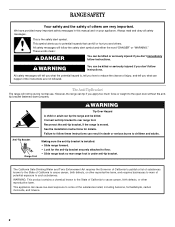
... models 8 General Cleaning 9 Oven Light 10 TROUBLESHOOTING 10 ACCESSORIES 11 WARRANTY 12 W10200356B You will need assistance, call us at www.whirlpool.com for purchasing this high-quality product. ® ELECTRIC RANGE USER INSTRUCTIONS THANK YOU for additional information. Para obtener acceso a "Instrucciones para el usuario de la estufa eléctrica" en...
... models 8 General Cleaning 9 Oven Light 10 TROUBLESHOOTING 10 ACCESSORIES 11 WARRANTY 12 W10200356B You will need assistance, call us at www.whirlpool.com for purchasing this high-quality product. ® ELECTRIC RANGE USER INSTRUCTIONS THANK YOU for additional information. Para obtener acceso a "Instrucciones para el usuario de la estufa eléctrica" en...
Owners Manual
Page 2
... to cause cancer, birth defects, or other reproductive harm, and requires businesses to warn of California to floor. • Slide range back so rear range foot is , tell you what can result in this manual and on your appliance. This appliance can be killed or seriously injured... if you don't immediately follow instructions. WARNING You can cause low-level exposure to rear range foot. RANGE SAFETY Your safety and the safety of others . WARNING Tip Over Hazard A child or adult can be killed. This is moved. ...
... to cause cancer, birth defects, or other reproductive harm, and requires businesses to warn of California to floor. • Slide range back so rear range foot is , tell you what can result in this manual and on your appliance. This appliance can be killed or seriously injured... if you don't immediately follow instructions. WARNING You can cause low-level exposure to rear range foot. RANGE SAFETY Your safety and the safety of others . WARNING Tip Over Hazard A child or adult can be killed. This is moved. ...
Owners Manual
Page 3
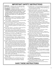
... THE RISK OF TIPPING OF THE RANGE, THE RANGE MUST BE SECURED BY PROPERLY INSTALLED ANTI-TIP DEVICES. Children should never be stored in an oven or near these pans or bowls during cooking may penetrate the broken cooktop and create a risk of electric shock, or fire. ■ ...avoid steam burn. IMPORTANT SAFETY INSTRUCTIONS WARNING: To reduce the risk of fire, electrical shock, injury to children in cabinets above a range or on the backguard of a range - TO CHECK IF THE DEVICES ARE INSTALLED PROPERLY, SLIDE RANGE FORWARD, LOOK FOR ANTI-TIP BRACKET SECURELY ATTACHED TO FLOOR, AND SLIDE...
... THE RISK OF TIPPING OF THE RANGE, THE RANGE MUST BE SECURED BY PROPERLY INSTALLED ANTI-TIP DEVICES. Children should never be stored in an oven or near these pans or bowls during cooking may penetrate the broken cooktop and create a risk of electric shock, or fire. ■ ...avoid steam burn. IMPORTANT SAFETY INSTRUCTIONS WARNING: To reduce the risk of fire, electrical shock, injury to children in cabinets above a range or on the backguard of a range - TO CHECK IF THE DEVICES ARE INSTALLED PROPERLY, SLIDE RANGE FORWARD, LOOK FOR ANTI-TIP BRACKET SECURELY ATTACHED TO FLOOR, AND SLIDE...
Owners Manual
Page 4
... the Timer. A tone will sound, and "Loc" will function with a.m. Do not press the CANCEL/OFF keypad because the oven will sound at www.whirlpool.com for 5 seconds. Press CANCEL/OFF when finished. Press TEMP/TIME "+" or "-" arrow pads to set in 5°F (5°C) increments between 170&#...Oven cavity light While the oven door is opened. The oven light will not come on and off . 2. SELF-CLEAN Self-clean cycle See the "Range Care" section. (on during the Self-Clean cycle. Repeat to begin the countdown. and p.m. 1. Check that the oven is running, but not ...
... the Timer. A tone will sound, and "Loc" will function with a.m. Do not press the CANCEL/OFF keypad because the oven will sound at www.whirlpool.com for 5 seconds. Press CANCEL/OFF when finished. Press TEMP/TIME "+" or "-" arrow pads to set in 5°F (5°C) increments between 170&#...Oven cavity light While the oven door is opened. The oven light will not come on and off . 2. SELF-CLEAN Self-clean cycle See the "Range Care" section. (on during the Self-Clean cycle. Repeat to begin the countdown. and p.m. 1. Check that the oven is running, but not ...
Owners Manual
Page 5
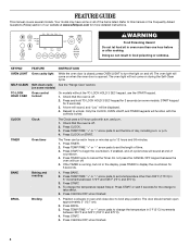
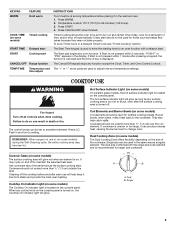
... is displayed. KEYPAD WARM FEATURE Hold warm COOK TIME (on some models) Timed cooking START TIME Delayed start START Cooking start CANCEL/OFF Range function TEMP/TIME Temperature and time adjust INSTRUCTIONS Food must be at 170°F (75°C) for larger size cookware. Burner bowls, when... dual size combines both the single and outer element and is in the warmed oven. 1. It may become hot. Press WARM. 2. REMEMBER: When range is recommended for 60 minutes (1.00 hours). 3. Single 5 When any surface cooking area is too hot to setting. Push in and turn on ,...
... is displayed. KEYPAD WARM FEATURE Hold warm COOK TIME (on some models) Timed cooking START TIME Delayed start START Cooking start CANCEL/OFF Range function TEMP/TIME Temperature and time adjust INSTRUCTIONS Food must be at 170°F (75°C) for larger size cookware. Burner bowls, when... dual size combines both the single and outer element and is in the warmed oven. 1. It may become hot. Press WARM. 2. REMEMBER: When range is recommended for 60 minutes (1.00 hours). 3. Single 5 When any surface cooking area is too hot to setting. Push in and turn on ,...


