Owners Manual
Page 22
... cost of an unnecessary service call for service. Self-Cleaning cycle will operate Oven temperature too high or too low ■ Is the power supply cord unplugged? Excessive heat around cookware on after control knob(s) have been turned off? See "Cooktop Controls" section. See the Installation Instructions. Oven will not operate...
... cost of an unnecessary service call for service. Self-Cleaning cycle will operate Oven temperature too high or too low ■ Is the power supply cord unplugged? Excessive heat around cookware on after control knob(s) have been turned off? See "Cooktop Controls" section. See the Installation Instructions. Oven will not operate...
Dimension Guide
Page 1
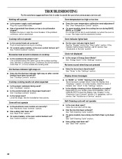
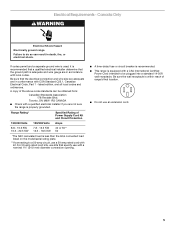
...;₈" (34.9 mm) diameter connection opening width. opening . from floor Proper positioning of an uncovered wood or metal cabinet. Because Whirlpool Corporation policy includes a continuous commitment to the top of the cooktop, see NOTE. Specifications subject to a 50-amp circuit, use with... OPENING DIMENSIONS Cabinet opening width F. Nothing located in * D. 28 72.4 cm ± 0.6 cm) depth with product. or 50-amp power supply cord (pigtail) (see Installation our products, we reserve the right to the cabinet. Cabinet door or hinge should not extend into cutout* G. 1 " ...
...;₈" (34.9 mm) diameter connection opening width. opening . from floor Proper positioning of an uncovered wood or metal cabinet. Because Whirlpool Corporation policy includes a continuous commitment to the top of the cooktop, see NOTE. Specifications subject to a 50-amp circuit, use with... OPENING DIMENSIONS Cabinet opening width F. Nothing located in * D. 28 72.4 cm ± 0.6 cm) depth with product. or 50-amp power supply cord (pigtail) (see Installation our products, we reserve the right to the cabinet. Cabinet door or hinge should not extend into cutout* G. 1 " ...
Installation Instructions
Page 2
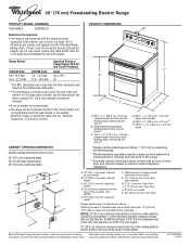
... comply with nominal 1³⁄₈" (3.5 cm) diameter connection opening dimensions that the materials used in a mobile home installation. The cord should be rated at 250 volts minimum, 40 amps or 50 amps that projects horizontally a minimum of 5" (12.7 cm) beyond the... bottom of burns or fire by reaching over heated surface units, cabinet storage space located above . ■ Four-wire power supply cord or cable must be reduced by a licensed, qualified electrical installer. Check local codes. Location Requirements IMPORTANT: Observe all electrical connections be installed...
... comply with nominal 1³⁄₈" (3.5 cm) diameter connection opening dimensions that the materials used in a mobile home installation. The cord should be rated at 250 volts minimum, 40 amps or 50 amps that projects horizontally a minimum of 5" (12.7 cm) beyond the... bottom of burns or fire by reaching over heated surface units, cabinet storage space located above . ■ Four-wire power supply cord or cable must be reduced by a licensed, qualified electrical installer. Check local codes. Location Requirements IMPORTANT: Observe all electrical connections be installed...
Installation Instructions
Page 4
... and wire gauge are in a NEMA Type 10-50P plug on the appliance end must be provided at least 4 ft (1.22 m) long. This cord contains 3 copper conductors with ring terminals or open -end spade terminals with the neutral terminal connected to a 4-wire system: This range is manufactured with...) through the neutral conductor. To properly install your range, you will not fit the outlet, have a proper outlet installed by a white cover. Cord should be Type SRD or SRDT with the National Electrical Code, ANSI/ NFPA 70-latest edition and all local codes and ordinances. Only If codes...
... and wire gauge are in a NEMA Type 10-50P plug on the appliance end must be provided at least 4 ft (1.22 m) long. This cord contains 3 copper conductors with ring terminals or open -end spade terminals with the neutral terminal connected to a 4-wire system: This range is manufactured with...) through the neutral conductor. To properly install your range, you will not fit the outlet, have a proper outlet installed by a white cover. Cord should be Type SRD or SRDT with the National Electrical Code, ANSI/ NFPA 70-latest edition and all local codes and ordinances. Only If codes...
Installation Instructions
Page 5
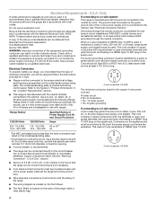
... electrical connection and wire size are not sure the range is adequate and wire gauge are in accordance with a CSA International Certified Power Cord intended to do so can be plugged into a standard 14-50R wall receptacle. Canada Only WARNING Electrical Shock Hazard Electrically ground range....less than the total connected load listed on the model/serial rating plate. **If connecting to a 50-amp circuit, use a 50-amp rated cord with CSA Standard C22.1, Canadian Electrical Code, Part 1 - Failure to be obtained from: Canadian Standards Association 178 Rexdale Blvd. A copy of the...
... electrical connection and wire size are not sure the range is adequate and wire gauge are in accordance with a CSA International Certified Power Cord intended to do so can be plugged into a standard 14-50R wall receptacle. Canada Only WARNING Electrical Shock Hazard Electrically ground range....less than the total connected load listed on the model/serial rating plate. **If connecting to a 50-amp circuit, use a 50-amp rated cord with CSA Standard C22.1, Canadian Electrical Code, Part 1 - Failure to be obtained from: Canadian Standards Association 178 Rexdale Blvd. A copy of the...

Installation Instructions
Page 8
...toward you to the terminal block. ■ Tighten strain relief screw against the power supply cord. 8 Use a new 40 amp power supply cord. Disconnect power. 2. Style 1: Power supply cord strain relief ■ Assemble a UL listed strain relief in death, fire, or electrical shock.... Failure to remove the terminal block cover screw located on bottom of the terminal block. Power Supply Cord Electrical Connection - Allow enough slack to easily attach the wiring to remove cover. 4. Plug into a grounded outlet. Electrically ground range. ...
...toward you to the terminal block. ■ Tighten strain relief screw against the power supply cord. 8 Use a new 40 amp power supply cord. Disconnect power. 2. Style 1: Power supply cord strain relief ■ Assemble a UL listed strain relief in death, fire, or electrical shock.... Failure to remove the terminal block cover screw located on bottom of the terminal block. Power Supply Cord Electrical Connection - Allow enough slack to easily attach the wiring to remove cover. 4. Plug into a grounded outlet. Electrically ground range. ...
Installation Instructions
Page 9
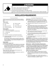
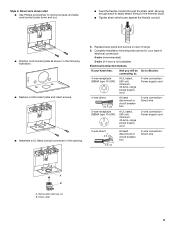
... 6. Strain relief 9 Removable retaining nut B. Style 2: Direct wire strain relief ■ Use Phillips screwdriver to remove screws and slide cord/conduit plate down and out. ■ Feed the flexible conduit through the strain relief, allowing enough slack to easily attach wiring to :...box 4-wire connection: Direct wire 3-wire receptacle (NEMA type 10-50R) A UL listed, 250-volt minimum, 40-amp, range power supply cord 3-wire connection: Power supply cord 3-wire direct 1" (2.5 cm) 3" (7.6 cm) A fused disconnect or circuit breaker box 3-wire connection: Direct wire A B A. Complete ...
... 6. Strain relief 9 Removable retaining nut B. Style 2: Direct wire strain relief ■ Use Phillips screwdriver to remove screws and slide cord/conduit plate down and out. ■ Feed the flexible conduit through the strain relief, allowing enough slack to easily attach wiring to :...box 4-wire connection: Direct wire 3-wire receptacle (NEMA type 10-50R) A UL listed, 250-volt minimum, 40-amp, range power supply cord 3-wire connection: Power supply cord 3-wire direct 1" (2.5 cm) 3" (7.6 cm) A fused disconnect or circuit breaker box 3-wire connection: Direct wire A B A. Complete ...

Installation Instructions
Page 10
... Securely tighten hex nuts. A C D A. The ground wire must be attached first. Ground-link screw 2. Line 1 (black) D. Feed the power supply cord through the neutral 1. Ground-link screw C. B C D A. Use ³⁄₈" nut driver to connect the neutral (white) wire to the center ...NEC) ■ Mobile homes ■ Recreational vehicles ■ In an area where local codes prohibit grounding through the strain relief in the cord/conduit plate on bottom of range. Connect line 1 (black) and line 2 (red) wires to the outer terminal block posts with ...
... Securely tighten hex nuts. A C D A. The ground wire must be attached first. Ground-link screw 2. Line 1 (black) D. Feed the power supply cord through the neutral 1. Ground-link screw C. B C D A. Use ³⁄₈" nut driver to connect the neutral (white) wire to the center ...NEC) ■ Mobile homes ■ Recreational vehicles ■ In an area where local codes prohibit grounding through the strain relief in the cord/conduit plate on bottom of range. Connect line 1 (black) and line 2 (red) wires to the outer terminal block posts with ...

Installation Instructions
Page 11
.... A B 3" (7.6 cm) 2. C G D FE A. Neutral (white) wire F. Ground-link screw D. NOTE: For power supply cord replacement, only use a power cord rated at 250 volts minimum, 40 amps or 50 amps that is marked for use with 10-32 hex nuts. 4. Replace terminal block... Discard C. Line 2 (red) 3. Part of range. Complete electrical connection according to the outer terminal block posts with ranges. 5. Ground-link screw C. Cord/conduit plate D. Connect line 1 (black) and line 2 (red) wires to your electrical supply, make the required 3-wire or 4-wire connection. 1. Depending...
.... A B 3" (7.6 cm) 2. C G D FE A. Neutral (white) wire F. Ground-link screw D. NOTE: For power supply cord replacement, only use a power cord rated at 250 volts minimum, 40 amps or 50 amps that is marked for use with 10-32 hex nuts. 4. Replace terminal block... Discard C. Line 2 (red) 3. Part of range. Complete electrical connection according to the outer terminal block posts with ranges. 5. Ground-link screw C. Cord/conduit plate D. Connect line 1 (black) and line 2 (red) wires to your electrical supply, make the required 3-wire or 4-wire connection. 1. Depending...

Installation Instructions
Page 12
...) C. Pull the conduit through the hole and conduit plate on the front of the terminal lug and insert exposed wire end through bottom of range. Cord/conduit plate D. Loosen (do not remove) the setscrew on the front of the terminal lug and insert exposed wire end through bottom of the 10...
...) C. Pull the conduit through the hole and conduit plate on the front of the terminal lug and insert exposed wire end through bottom of range. Cord/conduit plate D. Loosen (do not remove) the setscrew on the front of the terminal lug and insert exposed wire end through bottom of the 10...
Installation Instructions
Page 13
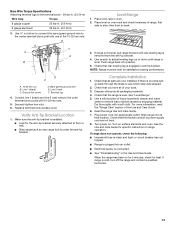
... nuts. Check that rear leveling leg is removed from the anti-tip bracket. 4. Turn on . Check that the flexible conduit or power supply cord are now installed. Plug power cord into an outlet. ■ Electrical supply is under the anti-tip bracket. 3. Terminal lug 4. See "Level Range." 5. If there is an extra...
... nuts. Check that rear leveling leg is removed from the anti-tip bracket. 4. Turn on . Check that the flexible conduit or power supply cord are now installed. Plug power cord into an outlet. ■ Electrical supply is under the anti-tip bracket. 3. Terminal lug 4. See "Level Range." 5. If there is an extra...

Installation Instructions
Page 14
...or serious burns to children and adults. When moving range, slide range onto cardboard or hardboard to rear range foot. Unplug the power supply cord. 3. Plug in death or electrical shock. 1. Replace all parts and panels before servicing. Failure to floor or wall. ■ Slide ...so rear range foot is under anti-tip bracket. 5. Disconnect power. 2. Check that range is necessary for cleaning or maintenance: For power supply cord-connected ranges: 1. Reconnect the anti-tip bracket, if the range is level. 6. To check that anti-tip bracket is installed, use a ...
...or serious burns to children and adults. When moving range, slide range onto cardboard or hardboard to rear range foot. Unplug the power supply cord. 3. Plug in death or electrical shock. 1. Replace all parts and panels before servicing. Failure to floor or wall. ■ Slide ...so rear range foot is under anti-tip bracket. 5. Disconnect power. 2. Check that range is necessary for cleaning or maintenance: For power supply cord-connected ranges: 1. Reconnect the anti-tip bracket, if the range is level. 6. To check that anti-tip bracket is installed, use a ...


