
English Manual
Page 1
... Read all precautions and instructions in the space above for future reference. CUSTOMER HOT LINE: 1-800-999-3756 Mon.-Fri., 6 a.m.-6 p.m. As a manufacturer, we are missing parts, we will guarantee complete satisfaction through assistance from our factory. Save this equipment. Write the serial number in this manual before using this manual for...
... Read all precautions and instructions in the space above for future reference. CUSTOMER HOT LINE: 1-800-999-3756 Mon.-Fri., 6 a.m.-6 p.m. As a manufacturer, we are missing parts, we will guarantee complete satisfaction through assistance from our factory. Save this equipment. Write the serial number in this manual before using this manual for...
English Manual
Page 2
TABLE OF CONTENTS IMPORTANT PRECAUTIONS 3 BEFORE YOU BEGIN 4 ASSEMBLY 5 ADJUSTMENTS 21 WEIGHT RESISTANCE CHART 23 TROUBLE-SHOOTING AND MAINTENANCE 24 CABLE DIAGRAMS 25 ORDERING REPLACEMENT PARTS Back Cover LIMITED WARRANTY Back Cover Note: A PART IDENTIFICATION CHART and a PART LIST/EXPLODED DRAWING are attached at the center of ICON Health & Fitness, Inc. 2 WEIDER is a registered trademark of this manual. Remove the PART IDENTIFICATION CHART and the PART LIST/EXPLODED DRAWING before beginning assembly.
TABLE OF CONTENTS IMPORTANT PRECAUTIONS 3 BEFORE YOU BEGIN 4 ASSEMBLY 5 ADJUSTMENTS 21 WEIGHT RESISTANCE CHART 23 TROUBLE-SHOOTING AND MAINTENANCE 24 CABLE DIAGRAMS 25 ORDERING REPLACEMENT PARTS Back Cover LIMITED WARRANTY Back Cover Note: A PART IDENTIFICATION CHART and a PART LIST/EXPLODED DRAWING are attached at the center of ICON Health & Fitness, Inc. 2 WEIDER is a registered trademark of this manual. Remove the PART IDENTIFICATION CHART and the PART LIST/EXPLODED DRAWING before beginning assembly.
English Manual
Page 3
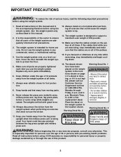
...for foot protection. 8. The weight system is the responsibility of the owner to ensure that the cables are adequately informed of this or any worn parts immediately. 6. If you are raised. Mountain Time, to protect the floor. 5. Make sure that the cables remain on the weight system in...leg press upright and military press arm. • Keep clear of this manual and in this area. Always disconnect the lat bar from moving parts. 9. Place the decal on the weight system in the locations shown on a level surface. Always wear athletic shoes for persons over the ...
...for foot protection. 8. The weight system is the responsibility of the owner to ensure that the cables are adequately informed of this or any worn parts immediately. 6. If you are raised. Mountain Time, to protect the floor. 5. Make sure that the cables remain on the weight system in...leg press upright and military press arm. • Keep clear of this manual and in this area. Always disconnect the lat bar from moving parts. 9. Place the decal on the weight system in the locations shown on a level surface. Always wear athletic shoes for persons over the ...
English Manual
Page 4
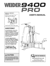
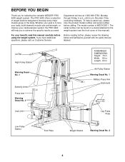
...of this manual carefully before calling. Mountain Time (excluding holidays). For your benefit, read this manual). If you for selecting the versatile WEIDER® PRO 9400 weight system. Lat Bar High Pulley Station Warning Decal No. 1 Butterfly Arms Press Arm Warning Decal No. 3 ASSEMBLED DIMENSIONS: Height... and familiarize yourself with the parts that are labeled. Ab Pulley Station Warning Decal No. 1 Military Press Arm Backrests Leg Lever Leg Press Plate Low Pulley Station Foot Plate Weight Stacks Warning Decal No. 2 4 The PRO 9400 offers a selection of weight stations...
...of this manual carefully before calling. Mountain Time (excluding holidays). For your benefit, read this manual). If you for selecting the versatile WEIDER® PRO 9400 weight system. Lat Bar High Pulley Station Warning Decal No. 1 Butterfly Arms Press Arm Warning Decal No. 3 ASSEMBLED DIMENSIONS: Height... and familiarize yourself with the parts that are labeled. Ab Pulley Station Warning Decal No. 1 Military Press Arm Backrests Leg Lever Leg Press Plate Low Pulley Station Foot Plate Weight Stacks Warning Decal No. 2 4 The PRO 9400 offers a selection of weight stations...
English Manual
Page 5
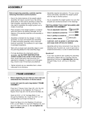
...(1) rubber mallet • Lubricant, such as you begin each assembly stage to see if it has been pre-attached. • Tighten all parts as grease or petroleum jelly, and soapy water will also be needed. • Assembly will be sure that assembly stage. • For ...: • Due to do not dispose of the Base (4). Insert six 5/16" x 2 1/2" Carriage Bolts (1) up through Friday, 6 a.m. If a part is packaged separately. • Wait until you assemble them, unless instructed to the many features of ratchet wrenches. ASSEMBLY Before beginning assembly, carefully read and...
...(1) rubber mallet • Lubricant, such as you begin each assembly stage to see if it has been pre-attached. • Tighten all parts as grease or petroleum jelly, and soapy water will also be needed. • Assembly will be sure that assembly stage. • For ...: • Due to do not dispose of the Base (4). Insert six 5/16" x 2 1/2" Carriage Bolts (1) up through Friday, 6 a.m. If a part is packaged separately. • Wait until you assemble them, unless instructed to the many features of ratchet wrenches. ASSEMBLY Before beginning assembly, carefully read and...
English Manual
Page 9
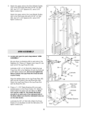
... on this side Lubricate 59 21 Welded Spacers 90 Make sure that the indicated holes are on the Press Frame (17). Locate and open the parts bag labeled "ARM ASSEMBLY." the Leg Press Arm must be a tight fit. The Plastic Bushings should fit on the Leg Press Plate (95) with the...
... on this side Lubricate 59 21 Welded Spacers 90 Make sure that the indicated holes are on the Press Frame (17). Locate and open the parts bag labeled "ARM ASSEMBLY." the Leg Press Arm must be a tight fit. The Plastic Bushings should fit on the Leg Press Plate (95) with the...
English Manual
Page 11
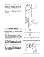
... 80 CABLE ASSEMBLY 16 16. Press two 1" Round Inner Caps (49) into the indicated end of the Military Press Arm (84). Locate and open the parts bags labeled "CABLE ASSEMBLY" and "PULLEYS." The approximate length of this section, fully unwind the four Cables. Attach the Pulley to the Top Frame (55...
... 80 CABLE ASSEMBLY 16 16. Press two 1" Round Inner Caps (49) into the indicated end of the Military Press Arm (84). Locate and open the parts bags labeled "CABLE ASSEMBLY" and "PULLEYS." The approximate length of this section, fully unwind the four Cables. Attach the Pulley to the Top Frame (55...

English Manual
Page 14
... with a 3/8" x 3 3/4" Bolt (88), 3/8" Washer (9), and a 3/8" Nylon Locknut (21). Be sure that the Cable Trap is turned to hold the Cable in place and that the parts are oriented as shown. 28 42 23 66 21 15 9 88 23 15 88 66 42 Inset shows view from other side 14 Route the...
... with a 3/8" x 3 3/4" Bolt (88), 3/8" Washer (9), and a 3/8" Nylon Locknut (21). Be sure that the Cable Trap is turned to hold the Cable in place and that the parts are oriented as shown. 28 42 23 66 21 15 9 88 23 15 88 66 42 Inset shows view from other side 14 Route the...
English Manual
Page 18
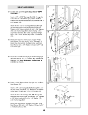
Locate and open the parts bag labeled "SEAT ASSEMBLY." Insert the 1/4" x 2 1/2" Carriage Bolt (92) through the indicated hole in the Leg Press Upright (56). Tighten a 1/4" Nylon Locknut (2) with a 1/4" Washer (10) ...
Locate and open the parts bag labeled "SEAT ASSEMBLY." Insert the 1/4" x 2 1/2" Carriage Bolt (92) through the indicated hole in the Leg Press Upright (56). Tighten a 1/4" Nylon Locknut (2) with a 1/4" Washer (10) ...
English Manual
Page 20
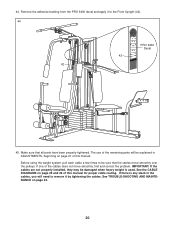
... smoothly, find and correct the problem. IMPORTANT: If the cables are not properly installed, they may be sure that all parts have been properly tightened. The use of the remaining parts will be explained in the cables, you will need to remove it to be damaged when heavy weight is any slack... TROUBLE-SHOOTING AND MAINTENANCE on page 24. 20 44. Before using the weight system, pull each cable a few times to the Front Upright (42). 44 PRO 9400 Decal 42 42 45. If one of this manual for proper cable routing. Remove the adhesive backing from the...
... smoothly, find and correct the problem. IMPORTANT: If the cables are not properly installed, they may be sure that all parts have been properly tightened. The use of the remaining parts will be explained in the cables, you will need to remove it to be damaged when heavy weight is any slack... TROUBLE-SHOOTING AND MAINTENANCE on page 24. 20 44. Before using the weight system, pull each cable a few times to the Front Upright (42). 44 PRO 9400 Decal 42 42 45. If one of this manual for proper cable routing. Remove the adhesive backing from the...
English Manual
Page 21
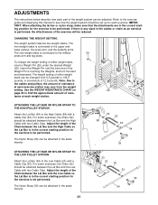
.... Adjust the length of the Chain between the Lat Bar and the High Cable with two Cable Clips. ADJUSTMENTS The instructions below describe how each part of the weight system can be performed. IMPORTANT: When attaching the lat bar or nylon strap, make sure that the attachments are in the correct...
.... Adjust the length of the Chain between the Lat Bar and the High Cable with two Cable Clips. ADJUSTMENTS The instructions below describe how each part of the weight system can be performed. IMPORTANT: When attaching the lat bar or nylon strap, make sure that the attachments are in the correct...
English Manual
Page 24
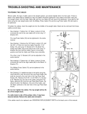
... in the cables before resistance is felt, the cables should be tightened. Re-attach the Pulley and Cable Trap to be replaced, see ORDERING REPLACEMENT PARTS on the weight system, can be tightened. Be sure that the Cable and Pulley move smoothly. If a cable tends to slip off the weight stack...
... in the cables before resistance is felt, the cables should be tightened. Re-attach the Pulley and Cable Trap to be replaced, see ORDERING REPLACEMENT PARTS on the weight system, can be tightened. Be sure that the Cable and Pulley move smoothly. If a cable tends to slip off the weight stack...
English Manual
Page 31
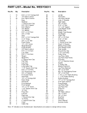
... 1 Press Pin 98 2 Bushing 99 2 3/8" Nylon Jamnut 100 1 3/8" x 3" Bolt 101 1 3/8" x 5" Bolt 102 2 Grip Pad 103 1 Ab Strap # 1 User's Manual # 1 Exercise Guide Note: "#" indicates a non-illustrated part. Specifications are subject to change without notice. Qty. Description Key No...
... 1 Press Pin 98 2 Bushing 99 2 3/8" Nylon Jamnut 100 1 3/8" x 3" Bolt 101 1 3/8" x 5" Bolt 102 2 Grip Pad 103 1 Ab Strap # 1 User's Manual # 1 Exercise Guide Note: "#" indicates a non-illustrated part. Specifications are subject to change without notice. Qty. Description Key No...
English Manual
Page 33
The MODEL NUMBER of the product (WEIDER® PRO 9400 weight system) 3. ICON's obligation under normal use and service conditions, for a period of ninety (90) days from state to any implied warranties of merchantability or ... product or damages with respect to state. The warranty extended hereunder is in its authorized service centers. The SERIAL NUMBER of the product (see the PART LIST and EXPLODED DRAWING attached at ICON's option, the product through Friday, 6 a.m. LIMITED WARRANTY ICON Health & Fitness, Inc. (ICON), warrants this manual). This warranty extends...
The MODEL NUMBER of the product (WEIDER® PRO 9400 weight system) 3. ICON's obligation under normal use and service conditions, for a period of ninety (90) days from state to any implied warranties of merchantability or ... product or damages with respect to state. The warranty extended hereunder is in its authorized service centers. The SERIAL NUMBER of the product (see the PART LIST and EXPLODED DRAWING attached at ICON's option, the product through Friday, 6 a.m. LIMITED WARRANTY ICON Health & Fitness, Inc. (ICON), warrants this manual). This warranty extends...


