
English Manual
Page 1
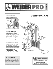
... HOT LINE. Model No. As a manufacturer, we are missing, we will provide immediate assistance, free of charge. MST CAUTION Read all precautions and instructions in the space above for future reference. Save this equipment. Patent Pending Visit our website at www.weiderfitness.com new products, prizes, fitness tips, and much more! USER'S MANUAL Serial Number Decal (Under Seat) QUESTIONS? CUSTOMER...
... HOT LINE. Model No. As a manufacturer, we are missing, we will provide immediate assistance, free of charge. MST CAUTION Read all precautions and instructions in the space above for future reference. Save this equipment. Patent Pending Visit our website at www.weiderfitness.com new products, prizes, fitness tips, and much more! USER'S MANUAL Serial Number Decal (Under Seat) QUESTIONS? CUSTOMER...
English Manual
Page 2
Remove the PART IDENTIFICATION CHART and the PART LIST/EXPLODED DRAWING before beginning assembly. WEIDER is a registered trademark of this manual. TABLE OF CONTENTS IMPORTANT PRECAUTIONS 3 BEFORE YOU BEGIN 4 ASSEMBLY 5 ADJUSTMENTS 22 WEIGHT RESISTANCE CHART 24 TROUBLESHOOTING 25 CABLE DIAGRAMS 26 ORDERING REPLACEMENT PARTS Back Cover LIMITED WARRANTY Back Cover Note: A PART IDENTIFICATION CHART and a PART LIST/EXPLODED DRAWING are attached in the center of ICON Health & Fitness, Inc. 2
Remove the PART IDENTIFICATION CHART and the PART LIST/EXPLODED DRAWING before beginning assembly. WEIDER is a registered trademark of this manual. TABLE OF CONTENTS IMPORTANT PRECAUTIONS 3 BEFORE YOU BEGIN 4 ASSEMBLY 5 ADJUSTMENTS 22 WEIGHT RESISTANCE CHART 24 TROUBLESHOOTING 25 CABLE DIAGRAMS 26 ORDERING REPLACEMENT PARTS Back Cover LIMITED WARRANTY Back Cover Note: A PART IDENTIFICATION CHART and a PART LIST/EXPLODED DRAWING are attached in the center of ICON Health & Fitness, Inc. 2
English Manual
Page 3
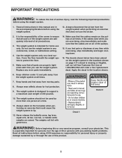
... from the weight system when performing an exercise that could cause the weight system to protect the floor. 5. If a decal is the responsibility of the owner to support a a maximum user weight of the pulleys. 15. Always disconnect the lat bar from moving parts. 8. Cover the floor beneath the weight system to tip. 12. Make sure that all instructions in this or any worn parts immediately. 14...
... from the weight system when performing an exercise that could cause the weight system to protect the floor. 5. If a decal is the responsibility of the owner to support a a maximum user weight of the pulleys. 15. Always disconnect the lat bar from moving parts. 8. Cover the floor beneath the weight system to tip. 12. Make sure that all instructions in this or any worn parts immediately. 14...
English Manual
Page 4
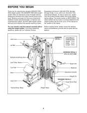
...). until 6 p.m. VKR* Arm Lat Bar Butterfly Arm/Press Arm Low Pulley Station Curl Pad Seat Leg Lever *Vertical Knee Raise WARNING DECAL 1 ASSEMBLED DIMENSIONS: Height: 77 in . Width: 81 in . The serial number can be found on each side) Weight Stack Squat Arm Backrest Adjustment Handle Weight Pin WARNING DECAL 2 Squat Knee Rest 4 The WEIDER® PRO 3550 weight system offers an impressive array of weight stations designed to achieve the specific results you...
...). until 6 p.m. VKR* Arm Lat Bar Butterfly Arm/Press Arm Low Pulley Station Curl Pad Seat Leg Lever *Vertical Knee Raise WARNING DECAL 1 ASSEMBLED DIMENSIONS: Height: 77 in . Width: 81 in . The serial number can be found on each side) Weight Stack Squat Arm Backrest Adjustment Handle Weight Pin WARNING DECAL 2 Squat Knee Rest 4 The WEIDER® PRO 3550 weight system offers an impressive array of weight stations designed to achieve the specific results you...
English Manual
Page 5
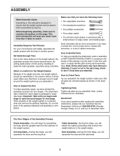
... a socket set, a set of open the parts bag(s) for that form the skeleton of the weight system. Questions? until assembly is enough room to walk around the weight system as you will require several hours. Mountain Time. Arm Assembly-During this stage, you will attach the cables and pulleys that connect the weight stations to do otherwise. Cable Assembly-During this stage, you will assemble the arms and the leg lever.
... a socket set, a set of open the parts bag(s) for that form the skeleton of the weight system. Questions? until assembly is enough room to walk around the weight system as you will require several hours. Mountain Time. Arm Assembly-During this stage, you will attach the cables and pulleys that connect the weight stations to do otherwise. Cable Assembly-During this stage, you will assemble the arms and the leg lever.

English Manual
Page 6
...sure that you begin assembling the weight system. Do not tighten the Nylon Locknuts yet. 2. Attach the tether on page 5 before you understand all of the Carriage Bolts to the Long Base (120) with four #10 x 1" Screws (14). Attach the Foot Plate to hold them in place. FRAME ASSEMBLY 1 1. Press a 2" Square ...Nylon Locknut; the Squat Knee Rest must be helpful to place tape over the heads of the information on the Pin (112) to the Short Base (2) with a #10 x 1" Screw (14). Press two 2" x 3" Inner Caps (58) into the open the parts bags labeled "FRAME ASSEMBLY 1" and "FRAME...
...sure that you begin assembling the weight system. Do not tighten the Nylon Locknuts yet. 2. Attach the tether on page 5 before you understand all of the Carriage Bolts to the Long Base (120) with four #10 x 1" Screws (14). Attach the Foot Plate to hold them in place. FRAME ASSEMBLY 1 1. Press a 2" Square ...Nylon Locknut; the Squat Knee Rest must be helpful to place tape over the heads of the information on the Pin (112) to the Short Base (2) with a #10 x 1" Screw (14). Press two 2" x 3" Inner Caps (58) into the open the parts bags labeled "FRAME ASSEMBLY 1" and "FRAME...

English Manual
Page 9
... is facing downward. Assemble the other weight stack in a Top Weight (45). Do not tighten the Bolts and Nylon Locknuts yet. Make sure that the Top Weight is turned so the grooved side is turned as shown. Insert the Weight Tube into the centers of two Weight Guides (42) into the lower end of the Weights are facing downward. Apply a number "10" decal to...
... is facing downward. Assemble the other weight stack in a Top Weight (45). Do not tighten the Bolts and Nylon Locknuts yet. Make sure that the Top Weight is turned so the grooved side is turned as shown. Insert the Weight Tube into the centers of two Weight Guides (42) into the lower end of the Weights are facing downward. Apply a number "10" decal to...

English Manual
Page 10
... 107-Lubricate 98 60 100, Lubricate 70 113 21 25 28 29 27 12. Do not tighten the Nylon Locknuts yet. ARM ASSEMBLY 13. Attach the Butterfly Frame (47) to pivot easily. 15. Press a 1 1/2" x 2" Inner Cap (21) into the Butterfly Frame (47). Open the parts bag labeled "ARM ASSEMBLY." Turn the Leg Lever (10) so that the bottom is on the two "L"-pins (60...
... 107-Lubricate 98 60 100, Lubricate 70 113 21 25 28 29 27 12. Do not tighten the Nylon Locknuts yet. ARM ASSEMBLY 13. Attach the Butterfly Frame (47) to pivot easily. 15. Press a 1 1/2" x 2" Inner Cap (21) into the Butterfly Frame (47). Open the parts bag labeled "ARM ASSEMBLY." Turn the Leg Lever (10) so that the bottom is on the two "L"-pins (60...
English Manual
Page 11
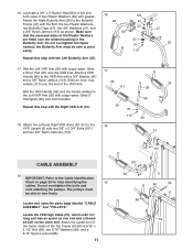
...) as shown. Attach a VKR Handle (66) to the 18 VKR Upright (5) with a 3/8" Washer (91) and a 3/8" Nylon Jamnut (113). Locate and open the parts bags labeled "CABLE ASSEMBLY" and "PULLEYS." Attach the Left and Right VKR Arms (30, 31) to the VKR Arm with two 3/8" x 2 3/4" Bolts (101) and two 3/8" Nylon Jamnuts (113). 31 CABLE ASSEMBLY 19. Lubricate a 3/8" x 3" Button Head Bolt (104) and both handles. 66 Repeat this step with grease.
...) as shown. Attach a VKR Handle (66) to the 18 VKR Upright (5) with a 3/8" Washer (91) and a 3/8" Nylon Jamnut (113). Locate and open the parts bags labeled "CABLE ASSEMBLY" and "PULLEYS." Attach the Left and Right VKR Arms (30, 31) to the VKR Arm with two 3/8" x 2 3/4" Bolts (101) and two 3/8" Nylon Jamnuts (113). 31 CABLE ASSEMBLY 19. Lubricate a 3/8" x 3" Button Head Bolt (104) and both handles. 66 Repeat this step with grease.

English Manual
Page 12
.... Attach the Pulley inside of the Cable two full turns into the Weight Tube. Remove the preattached 3 1/2" Pulleys (78 [only one end and a ball on the Top Frame (6) with a 3/8" x 1 3/4" Bolt (93) and a 3/8" Nylon Locknut (87). 21. Route the eyelet end of the VKR High Cable (74). Screw the end of the groove under a 3 1/2" Pulley (78). Make sure that the small pin on the Weight...
.... Attach the Pulley inside of the Cable two full turns into the Weight Tube. Remove the preattached 3 1/2" Pulleys (78 [only one end and a ball on the Top Frame (6) with a 3/8" x 1 3/4" Bolt (93) and a 3/8" Nylon Locknut (87). 21. Route the eyelet end of the VKR High Cable (74). Screw the end of the groove under a 3 1/2" Pulley (78). Make sure that the small pin on the Weight...
English Manual
Page 15
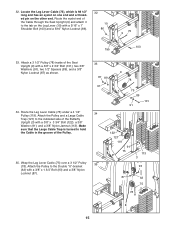
... 62 75 78 15 Route the eyelet end of the Butterfly Upright (3) with a 3/8" x 2 3/4" Bolt (101), two 3/8" Washers (91), two 1/2" Spacers (89), and a 3/8" Nylon Locknut (87) as shown. 34. Locate the Leg Lever Cable (75), which is turned to hold the Cable in the groove of the Seat Upright (9) with a 3/8" x 3 3/4" Bolt (122), a 3/8" Washer (91), and a 3/8" Nylon Jamnut (113). Attach the Pulley to the tab...
... 62 75 78 15 Route the eyelet end of the Butterfly Upright (3) with a 3/8" x 2 3/4" Bolt (101), two 3/8" Washers (91), two 1/2" Spacers (89), and a 3/8" Nylon Locknut (87) as shown. 34. Locate the Leg Lever Cable (75), which is turned to hold the Cable in the groove of the Seat Upright (9) with a 3/8" x 3 3/4" Bolt (122), a 3/8" Washer (91), and a 3/8" Nylon Jamnut (113). Attach the Pulley to the tab...

English Manual
Page 19
... the small pin on the Long Base (120) with a 3/8" x 1 3/4" Bolt (93) and a 3/8" Nylon Locknut (87). 68 73 87 78 100 120 6 87 93 119 73 50. Locate and open the parts bag labeled "SEAT ASSEMBLY." 48. ond set of the Squat Cable (73). Wrap the Squat Cable (73) over the weight stack while you screw the end of the groove under a 3 1/2" Pulley 48...
... the small pin on the Long Base (120) with a 3/8" x 1 3/4" Bolt (93) and a 3/8" Nylon Locknut (87). 68 73 87 78 100 120 6 87 93 119 73 50. Locate and open the parts bag labeled "SEAT ASSEMBLY." 48. ond set of the Squat Cable (73). Wrap the Squat Cable (73) over the weight stack while you screw the end of the groove under a 3 1/2" Pulley 48...

English Manual
Page 21
Attach the Squat Arm (32) to the Squat Bracket (37) with four 1/4" x 3/4" Screws (114). er to remove the slack by tightening the cables. Next, pull the Knob and slide the Squat Bracket (37) down onto the Squat Slider (38). The use of the remaining parts will need to the bottom of this manual for proper cable routing. See the CABLE DIAGRAMS on page 25. 21 Tighten all...
Attach the Squat Arm (32) to the Squat Bracket (37) with four 1/4" x 3/4" Screws (114). er to remove the slack by tightening the cables. Next, pull the Knob and slide the Squat Bracket (37) down onto the Squat Slider (38). The use of the remaining parts will need to the bottom of this manual for proper cable routing. See the CABLE DIAGRAMS on page 25. 21 Tighten all...
English Manual
Page 22
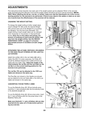
... in the cables or chain as press arms, insert the "L"-pins w/Tethers (60) into the press holes in the same way. ADJUSTMENTS The instructions below describe how each weight stack can be changed from the weight setting. If there is any exercise. 60 Butterfly Holes 3 26 47 Press Holes 25 22 Turn the bent end downward. ATTACHING THE LAT BAR, ROW BAR, OR HANDLE TO THE HIGH PULLEY STATION...
... in the cables or chain as press arms, insert the "L"-pins w/Tethers (60) into the press holes in the same way. ADJUSTMENTS The instructions below describe how each weight stack can be changed from the weight setting. If there is any exercise. 60 Butterfly Holes 3 26 47 Press Holes 25 22 Turn the bent end downward. ATTACHING THE LAT BAR, ROW BAR, OR HANDLE TO THE HIGH PULLEY STATION...

English Manual
Page 23
... Curl Pad (17), first remove the seat from the seat frame (see ADJUSTING THE SQUAT ARM, SEAT, OR BUTTERFLY BACKREST, above). When the Squat Knee Rest (41) is not in use , remove the Curl Frame Knob (76) and the Curl Frame (12) from the Seat Upright (9). Tighten the Curl Frame Knob (76) into the seat frame. Reinsert the seat into the Seat Upright and the Curl Frame...
... Curl Pad (17), first remove the seat from the seat frame (see ADJUSTING THE SQUAT ARM, SEAT, OR BUTTERFLY BACKREST, above). When the Squat Knee Rest (41) is not in use , remove the Curl Frame Knob (76) and the Curl Frame (12) from the Seat Upright (9). Tighten the Curl Frame Knob (76) into the seat frame. Reinsert the seat into the Seat Upright and the Curl Frame...

English Manual
Page 24
... 254 270 PRESS ARM (lbs.) 21 42 59 78 97 115 132 153 167 180 192 24 WEIGHT RESISTANCE CHART The chart below shows the approximate weight resistance at each weight station may vary due to differences in individual weight plates as well as friction between the cables, pulleys, and weight guides. "Top" refers to the 10-pound weight plates. Note: The actual resistance at each...
... 254 270 PRESS ARM (lbs.) 21 42 59 78 97 115 132 153 167 180 192 24 WEIGHT RESISTANCE CHART The chart below shows the approximate weight resistance at each weight station may vary due to differences in individual weight plates as well as friction between the cables, pulleys, and weight guides. "Top" refers to the 10-pound weight plates. Note: The actual resistance at each...
English Manual
Page 25
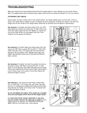
...), 3/8" x 2" Bolt (100), 3 1/2" Pulley (78), and Cable Trap (68) from the Pulley Plates (63). If a cable slips off the weight stacks. Remove the cable and re-install it. The weight system can be removed from the 1/2" Washer (1). To tighten the cables, first insert the weight pins into the Weight Tube (43). See drawing 3. To tighten the other five cables, first remove the upper or lower 3/8" Nylon Locknut (87), 3/8" x 2" Bolt 3 (100), 3 1/2" Pulley (78), and Cable Trap...
...), 3/8" x 2" Bolt (100), 3 1/2" Pulley (78), and Cable Trap (68) from the Pulley Plates (63). If a cable slips off the weight stacks. Remove the cable and re-install it. The weight system can be removed from the 1/2" Washer (1). To tighten the cables, first insert the weight pins into the Weight Tube (43). See drawing 3. To tighten the other five cables, first remove the upper or lower 3/8" Nylon Locknut (87), 3/8" x 2" Bolt 3 (100), 3 1/2" Pulley (78), and Cable Trap...

English Manual
Page 26
... the cables have been assembled correctly. CABLE DIAGRAMS The cable identification chart below shows the ends of each cable and the lengths of the cables. The numbers in the diagrams show the proper routing of the cables. Cable Identification Chart Butterfly Cable (69)-58" VKR Low Cable (72)-259 1/2" Squat Cable (73)-175 1/4" VKR High Cable (74)-82 1/4" Leg Lever Cable (75)-98 1/2" Lat Cable (88)-89 1/4" Lat Cable (88) 4 2 1 5 4 Butterfly Cable (69) 2 3 1 3 1 Squat Cable (73...
... the cables have been assembled correctly. CABLE DIAGRAMS The cable identification chart below shows the ends of each cable and the lengths of the cables. The numbers in the diagrams show the proper routing of the cables. Cable Identification Chart Butterfly Cable (69)-58" VKR Low Cable (72)-259 1/2" Squat Cable (73)-175 1/4" VKR High Cable (74)-82 1/4" Leg Lever Cable (75)-98 1/2" Lat Cable (88)-89 1/4" Lat Cable (88) 4 2 1 5 4 Butterfly Cable (69) 2 3 1 3 1 Squat Cable (73...
English Manual
Page 31
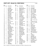
...x 3" Button Head Bolt 2" Square Inner Cap 3/8" x 2 1/2" Carriage Bolt 3/8" x 3" Bolt Nut Clip Knee Pad Cap 5/16" x 2 1/2" Carriage Bolt Inner Cap w/Hole Pin w/Tether 3/8" Nylon Jamnut 1/4" x 3/4" Screw Adjustment Knob 3/4" x 1 1/2" Inner Cap 1 1/4" Square Inner Cap 1/2" Nut 4 1/2" Pulley Long Base Large Cable Trap 3/8" x 3 3/4" Bolt Knee Rest Bumper 3/4" Spacer 2" x 2 1/2" Inner Cap Butterfly Arm Stop User's Manual Exercise Guide Note: "#" indicates a non-illustrated part. Description Key No. Qty. Qty. Specifications are subject to change without notice. Qty. PART LIST-Model No...
...x 3" Button Head Bolt 2" Square Inner Cap 3/8" x 2 1/2" Carriage Bolt 3/8" x 3" Bolt Nut Clip Knee Pad Cap 5/16" x 2 1/2" Carriage Bolt Inner Cap w/Hole Pin w/Tether 3/8" Nylon Jamnut 1/4" x 3/4" Screw Adjustment Knob 3/4" x 1 1/2" Inner Cap 1 1/4" Square Inner Cap 1/2" Nut 4 1/2" Pulley Long Base Large Cable Trap 3/8" x 3 3/4" Bolt Knee Rest Bumper 3/4" Spacer 2" x 2 1/2" Inner Cap Butterfly Arm Stop User's Manual Exercise Guide Note: "#" indicates a non-illustrated part. Description Key No. Qty. Qty. Specifications are subject to change without notice. Qty. PART LIST-Model No...
English Manual
Page 33
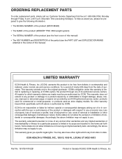
...). This warranty extends only to give the following information: • The MODEL NUMBER of the product (WESY38322) • The NAME of the product (WEIDER® PRO 3550 weight system) • The SERIAL NUMBER of the product (see the front cover of this manual) • The KEY NUMBER and DESCRIPTION of the part(s) (see the PART LIST and EXPLODED DRAWING attached in connection with the use , costs of removal or installation or other...
...). This warranty extends only to give the following information: • The MODEL NUMBER of the product (WESY38322) • The NAME of the product (WEIDER® PRO 3550 weight system) • The SERIAL NUMBER of the product (see the front cover of this manual) • The KEY NUMBER and DESCRIPTION of the part(s) (see the PART LIST and EXPLODED DRAWING attached in connection with the use , costs of removal or installation or other...


