
Uk Manual
Page 4
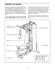
... can be found on a decal attached to develop every major muscle group of this manual. Lat Bar High Pulley Station Butterfly Arm/Press Arm Backrest Seat Leg Lever Foot Plate Press Frame Lock Weight Stack ASSEMBLED DIMENSIONS: Height: 79 in. (200 cm) Width: 37 in. (93 cm) Depth: 52 in. (132 cm... of weight stations designed to the weight system (see the front cover of the body. Whether your benefit, read this manual for selecting the versatile WEIDER® PRO 2000 weight system. If you have questions after reading this manual, see the front cover of the decal).
... can be found on a decal attached to develop every major muscle group of this manual. Lat Bar High Pulley Station Butterfly Arm/Press Arm Backrest Seat Leg Lever Foot Plate Press Frame Lock Weight Stack ASSEMBLED DIMENSIONS: Height: 79 in. (200 cm) Width: 37 in. (93 cm) Depth: 52 in. (132 cm... of weight stations designed to the weight system (see the front cover of the body. Whether your benefit, read this manual for selecting the versatile WEIDER® PRO 2000 weight system. If you have questions after reading this manual, see the front cover of the decal).
Uk Manual
Page 7
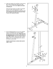
... an M8 x 63mm Bolt (66), two M8 Washers (71), and an M8 Nylon Locknut (69). Insert two Weight Guides (10) into the same holes. the Press Frame Lock must pivot easily. 66 39 71 71 69 3 69 69 1 58 3. Secure the Weight Guides in steps 1 and 3. 10 17 68 Holes 70... 2 M8 x 63mm Carriage Bolts (58) and two M8 Nylon Locknuts (69). Set two Weight Bumpers (17) over the indicated 3 holes in the Stabilizer (2). 2. Attach the Press Frame Lock (39) to the bottom of the Weight Guides. Attach the Upright (3) to the Base (1) with two M10 x 70mm Bolts (57), two M10 Washers...
... an M8 x 63mm Bolt (66), two M8 Washers (71), and an M8 Nylon Locknut (69). Insert two Weight Guides (10) into the same holes. the Press Frame Lock must pivot easily. 66 39 71 71 69 3 69 69 1 58 3. Secure the Weight Guides in steps 1 and 3. 10 17 68 Holes 70... 2 M8 x 63mm Carriage Bolts (58) and two M8 Nylon Locknuts (69). Set two Weight Bumpers (17) over the indicated 3 holes in the Stabilizer (2). 2. Attach the Press Frame Lock (39) to the bottom of the Weight Guides. Attach the Upright (3) to the Base (1) with two M10 x 70mm Bolts (57), two M10 Washers...

Uk Manual
Page 9
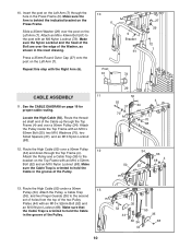
... sure that the barrel of the Bolt Set is inserted through both sides of the bracket on the side shown. Grease 8 81 9 81 8. Attach the Press Frame to the Left Arm (7) with the bracket on the Seat Frame. Repeat this step with the Bolt Set. Grease the M10 x 57mm Bolt Set... (81) and attach the Leg Lever to an M10 x 125mm Bolt (64). the Leg Lever must pivot easily. 8 64 70 4 Grease 70 68 9. Orient the Press Frame (5) with two M6 x 58mm Screws (65) and two M6 Washers (73). Apply grease to the Seat Frame (8) with the Right Arm (6). 5 Bracket 9 6 7 20 73...
... sure that the barrel of the Bolt Set is inserted through both sides of the bracket on the side shown. Grease 8 81 9 81 8. Attach the Press Frame to the Left Arm (7) with the bracket on the Seat Frame. Repeat this step with the Bolt Set. Grease the M10 x 57mm Bolt Set... (81) and attach the Leg Lever to an M10 x 125mm Bolt (64). the Leg Lever must pivot easily. 8 64 70 4 Grease 70 68 9. Orient the Press Frame (5) with two M6 x 58mm Screws (65) and two M6 Washers (73). Apply grease to the Seat Frame (8) with the Right Arm (6). 5 Bracket 9 6 7 20 73...
Uk Manual
Page 10
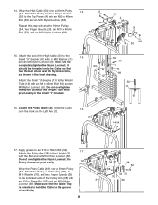
... shown in the groove of the Bolt are over a 90mm Pulley (34). Make sure that the Cable Trap is oriented to the bracket on the Press Frame. Make sure the Nylon Locknut and the head of the Pulley. 29 50 55 4 37 34 70 37 70 68 34 36 4 68 50... (52) and an M10 Nylon Locknut (68). Attach the Pulley, a Cable Trap (36), and two Finger Guards (35) to hold the Cable in the Press Frame (5). Press a 25mm Round Outer Cap (27) onto the post on page 19 for proper cable routing. Route the High Cable (50) under a 90mm 13 Pulley (34...
... shown in the groove of the Bolt are over a 90mm Pulley (34). Make sure that the Cable Trap is oriented to the bracket on the Press Frame. Make sure the Nylon Locknut and the head of the Pulley. 29 50 55 4 37 34 70 37 70 68 34 36 4 68 50... (52) and an M10 Nylon Locknut (68). Attach the Pulley, a Cable Trap (36), and two Finger Guards (35) to hold the Cable in the Press Frame (5). Press a 25mm Round Outer Cap (27) onto the post on page 19 for proper cable routing. Route the High Cable (50) under a 90mm 13 Pulley (34...
Uk Manual
Page 11
...), two Finger Guards (35), an M10 x 46mm Bolt (53), and an M10 Nylon Locknut (68). 53 35 4 35 35 68 34 50 15. Wrap the Press Cable (49) over a 90mm Pulley 14 (34). the Weight Tube must pivot easily. Slide the Cable 16 onto the hook on the Left Arm (7). the... Pulley Arm must pivot easily in the inset drawing. Do not overtighten the Nylon Locknut; Locate the Press Cable (49). Make sure that two threads show past the Nylon Locknut, as shown in the Small "U"-bracket. 69 12 50 60 11 71 69...
...), two Finger Guards (35), an M10 x 46mm Bolt (53), and an M10 Nylon Locknut (68). 53 35 4 35 35 68 34 50 15. Wrap the Press Cable (49) over a 90mm Pulley 14 (34). the Weight Tube must pivot easily. Slide the Cable 16 onto the hook on the Left Arm (7). the... Pulley Arm must pivot easily in the inset drawing. Do not overtighten the Nylon Locknut; Locate the Press Cable (49). Make sure that two threads show past the Nylon Locknut, as shown in the Small "U"-bracket. 69 12 50 60 11 71 69...

Uk Manual
Page 12
...(3) with an M10 x 70mm Bolt (57), an M10 Washer (70), and an M10 Nylon Locknut (68). Wrap the Press Cable (49) over a 90mm Pulley (34). Attach the eyelet 21 on the Right Arm (6). 20 49 21. Do ...the Bolt and an M10 Nylon Locknut (68). the Pulley Arm must pivot easily. Slide the end of the Press Cable (49) onto the hook on the Cable to hold the Cable in the groove of a Pulley Arm ... 46mm Bolt (53) and an M10 Nylon Locknut (68). 49 34 35 68 35 53 42 19. Wrap the Press Cable (49) under a 90mm Pulley 18 (34). Attach the Pulley and two Finger Guards (35) to the indicated...
...(3) with an M10 x 70mm Bolt (57), an M10 Washer (70), and an M10 Nylon Locknut (68). Wrap the Press Cable (49) over a 90mm Pulley (34). Attach the eyelet 21 on the Right Arm (6). 20 49 21. Do ...the Bolt and an M10 Nylon Locknut (68). the Pulley Arm must pivot easily. Slide the end of the Press Cable (49) onto the hook on the Cable to hold the Cable in the groove of a Pulley Arm ... 46mm Bolt (53) and an M10 Nylon Locknut (68). 49 34 35 68 35 53 42 19. Wrap the Press Cable (49) under a 90mm Pulley 18 (34). Attach the Pulley and two Finger Guards (35) to the indicated...

Uk Manual
Page 15
SEAT ASSEMBLY 30. Attach the Seat (19), oriented as shown, to the Upright (3) with two M6 x 63mm Screws (67) and two M6 Washers (73). 30 18 Wide End 67 73 3 73 67 31. Attach the Backrest (18) to the Seat Frame (8) with the other Pad Tube (45) and the Seat Frame (8). 32 22 21 9 45 8 21 45 22 15 Repeat this step with four M6 x 16mm Screws (40). 31 19 Wide End 8 40 40 32. Slide a Pad Tube (45) through the hole in the Leg Lever (9). Slide two Foam Pads (21) onto the ends of the Pad Tube. Then, press two Pad Caps (22) onto the Pad Tube.
SEAT ASSEMBLY 30. Attach the Seat (19), oriented as shown, to the Upright (3) with two M6 x 63mm Screws (67) and two M6 Washers (73). 30 18 Wide End 67 73 3 73 67 31. Attach the Backrest (18) to the Seat Frame (8) with the other Pad Tube (45) and the Seat Frame (8). 32 22 21 9 45 8 21 45 22 15 Repeat this step with four M6 x 16mm Screws (40). 31 19 Wide End 8 40 40 32. Slide a Pad Tube (45) through the hole in the Leg Lever (9). Slide two Foam Pads (21) onto the ends of the Pad Tube. Then, press two Pad Caps (22) onto the Pad Tube.
Uk Manual
Page 17
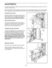
... the correct form for each time you use solvents. Replace any worn parts immediately. Remove the Lat Bar when performing exercises that do press arm exercises, push the Press Frame Lock (39) to the position shown to find the approximate amount of the Weight Pin touches the Weights. Turn the bent end... (82) and the M8 x 70mm Carriage Bolt (86). Refer to the accompanying exercise guide to adjust the weight system. To do fly exercises, lift the Press Frame Lock until the Press Arms are properly tightened each exercise.
... the correct form for each time you use solvents. Replace any worn parts immediately. Remove the Lat Bar when performing exercises that do press arm exercises, push the Press Frame Lock (39) to the position shown to find the approximate amount of the Weight Pin touches the Weights. Turn the bent end... (82) and the M8 x 70mm Carriage Bolt (86). Refer to the accompanying exercise guide to adjust the weight system. To do fly exercises, lift the Press Frame Lock until the Press Arms are properly tightened each exercise.
Uk Manual
Page 18
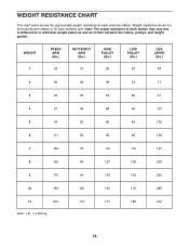
Note: The actual resistance at each exercise station. WEIGHT 1 PRESS ARM (lbs.) 35 BUTTERFLY ARM (lbs.) 19 HIGH PULLEY (lbs.) 26 LOW PULLEY (lbs.) 29 LEG LEVER (lbs.) 48 2 50 28 38 43 71 3 66 ...
Note: The actual resistance at each exercise station. WEIGHT 1 PRESS ARM (lbs.) 35 BUTTERFLY ARM (lbs.) 19 HIGH PULLEY (lbs.) 26 LOW PULLEY (lbs.) 29 LEG LEVER (lbs.) 48 2 50 28 38 43 71 3 66 ...
Uk Manual
Page 19
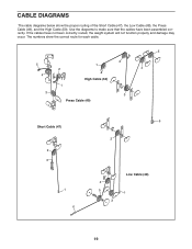
Use the diagrams to make sure that the cables have not been correctly routed, the weight system will not function properly and damage may occur. The numbers show the proper routing of the Short Cable (47), the Low Cable (48), the Press Cable (49), and the High Cable (50). If the cables have been assembled correctly. CABLE DIAGRAMS The cable diagrams below show the correct route for each cable. 5 5 2 4 1 2 1 4 High Cable (50) 3 3 Press Cable (49) Short Cable (47) 2 3 1 6 6 2 4 5 3 Low Cable (48) 1 19
Use the diagrams to make sure that the cables have not been correctly routed, the weight system will not function properly and damage may occur. The numbers show the proper routing of the Short Cable (47), the Low Cable (48), the Press Cable (49), and the High Cable (50). If the cables have been assembled correctly. CABLE DIAGRAMS The cable diagrams below show the correct route for each cable. 5 5 2 4 1 2 1 4 High Cable (50) 3 3 Press Cable (49) Short Cable (47) 2 3 1 6 6 2 4 5 3 Low Cable (48) 1 19
Uk Manual
Page 21
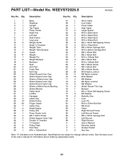
...'s manual for information about ordering replacement parts. 21 WEEVSY2026.0 R0706A Key No. Description 1 1 Base 2 1 Stabilizer 3 1 Upright 4 1 Top Frame 5 1 Press Frame 6 1 Right Arm 7 1 Left Arm 8 1 Seat Frame 9 1 Leg Lever 10 2 Weight Guide 11 1 Small "U"-bracket 12 1 Weight Tube 13...33 3 Cable Clip 34 13 90mm Pulley 35 20 Finger Guard 36 7 Cable Trap 37 4 Small Spacer 38 2 Pulley Arm 39 1 Press Frame Lock 40 4 M6 x 16mm Screw 41 2 50mm Square Outer Cap 42 1 Double "U"-bracket 43 1 "U"-bracket 44 2 Pulley Plate...
...'s manual for information about ordering replacement parts. 21 WEEVSY2026.0 R0706A Key No. Description 1 1 Base 2 1 Stabilizer 3 1 Upright 4 1 Top Frame 5 1 Press Frame 6 1 Right Arm 7 1 Left Arm 8 1 Seat Frame 9 1 Leg Lever 10 2 Weight Guide 11 1 Small "U"-bracket 12 1 Weight Tube 13...33 3 Cable Clip 34 13 90mm Pulley 35 20 Finger Guard 36 7 Cable Trap 37 4 Small Spacer 38 2 Pulley Arm 39 1 Press Frame Lock 40 4 M6 x 16mm Screw 41 2 50mm Square Outer Cap 42 1 Double "U"-bracket 43 1 "U"-bracket 44 2 Pulley Plate...


