
Instruction Manual
Page 1
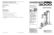
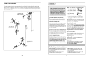
... part(s) (see the PART LIST and EXPLODED DRAWING in the centre of this manual) Part No. 232527 R0805A Printed in this manual before using this manual for future reference. WEEVSY1975.0 Serial No. Write the serial number in the space above for future reference. ORDERING REPLACEMENT PARTS To order replacement parts, contact the ICON Health & Fitness Ltd. If you , please be prepared to providing complete customer satisfaction. USER'S MANUAL Serial Number Decal (Under Seat) QUESTIONS? Model...
... part(s) (see the PART LIST and EXPLODED DRAWING in the centre of this manual) Part No. 232527 R0805A Printed in this manual before using this manual for future reference. WEEVSY1975.0 Serial No. Write the serial number in the space above for future reference. ORDERING REPLACEMENT PARTS To order replacement parts, contact the ICON Health & Fitness Ltd. If you , please be prepared to providing complete customer satisfaction. USER'S MANUAL Serial Number Decal (Under Seat) QUESTIONS? Model...
Instruction Manual
Page 2
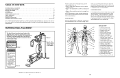
... REPLACEMENT PARTS Back Cover Note: A PART IDENTIFICATION CHART and a PART LIST/EXPLODED DRAWING are : • Rest for three minutes after each set for a short period of your arms and legs. If a decal is missing, or if it is an effective way to spend the first couple of this manual. Plan to increase flexibility. List the date, the exercises performed, the resistance used, and the numbers of arm...
... REPLACEMENT PARTS Back Cover Note: A PART IDENTIFICATION CHART and a PART LIST/EXPLODED DRAWING are : • Rest for three minutes after each set for a short period of your arms and legs. If a decal is missing, or if it is an effective way to spend the first couple of this manual. Plan to increase flexibility. List the date, the exercises performed, the resistance used, and the numbers of arm...
Instruction Manual
Page 3
... set " is : • Plan strength training workouts on the pulleys. 13. Replace any commercial, rental, or institutional setting. 4. Always secure the weight stack with great force. 15. Always stand on Tuesday and Thursday. • Rest from moving parts. 10. Never release the arms, leg lever, lat bar, or handle strap while weights are important factors in this manual. 2. ICON assumes no more than by changing the amount of resistance used...
... set " is : • Plan strength training workouts on the pulleys. 13. Replace any commercial, rental, or institutional setting. 4. Always secure the weight stack with great force. 15. Always stand on Tuesday and Thursday. • Rest from moving parts. 10. Never release the arms, leg lever, lat bar, or handle strap while weights are important factors in this manual. 2. ICON assumes no more than by changing the amount of resistance used...
Instruction Manual
Page 4
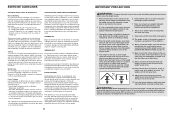
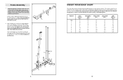
... lifted off the pulleys often, it . Arm Shroud Backrest Seat Right Side Leg Lever Pin Leg Lever Low Pulley Station Foot Plate Weights *Anchor Hole Left Side ASSEMBLED DIMENSIONS: Height: 76 in. / 193 cm Width: 37 in. / 94 cm Depth: 48 in the "U"-bracket. If the cables are properly tightened each time the weight system is removed from the Cable. If the cables need to right and...
... lifted off the pulleys often, it . Arm Shroud Backrest Seat Right Side Leg Lever Pin Leg Lever Low Pulley Station Foot Plate Weights *Anchor Hole Left Side ASSEMBLED DIMENSIONS: Height: 76 in. / 193 cm Width: 37 in. / 94 cm Depth: 48 in the "U"-bracket. If the cables are properly tightened each time the weight system is removed from the Cable. If the cables need to right and...
Instruction Manual
Page 5
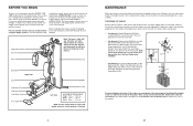
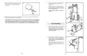
... will attach the cables and pulleys that the cable traps do otherwise. Cable Assembly-During this page. Before beginning assembly, make sure that the cables, cable traps, and finger guards have a socket set, a set of the weight system. Make sure that form the skeleton of open the parts bag for that the weight system can be assembled in assembly, we have been pre-attached. This brief introduction will also need grease...
... will attach the cables and pulleys that the cable traps do otherwise. Cable Assembly-During this page. Before beginning assembly, make sure that the cables, cable traps, and finger guards have a socket set, a set of the weight system. Make sure that form the skeleton of open the parts bag for that the weight system can be assembled in assembly, we have been pre-attached. This brief introduction will also need grease...
Instruction Manual
Page 6
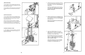
... beginning assembly, make sure you understand the information in the Weight Guides are nearer the bot- Note: It may vary due to the PART IDENTIFICATION CHART in the centre of tape over the bolt heads to the 12.5 lb. The other numbers refer to hold them in individual weight plates as well as friction between the cables, pulleys, and weight guides. Attach the Upright (3) to...
... beginning assembly, make sure you understand the information in the Weight Guides are nearer the bot- Note: It may vary due to the PART IDENTIFICATION CHART in the centre of tape over the bolt heads to the 12.5 lb. The other numbers refer to hold them in individual weight plates as well as friction between the cables, pulleys, and weight guides. Attach the Upright (3) to...
Instruction Manual
Page 7
... Bolts (68), two M8 Washers (59), and two M8 Nylon Locknuts (58). Remove the Curl Pad (14) and replace the 50mm Round Inner Cap (30) into the six Weights (22). Attach the Front Leg (7) to the Front Leg (7) in the Upright (3) and the Pivot Frame (5) as shown. Slide the Top Weight onto the Weight Guides (21). 21 25 Pin Hole 21 Grease Pin 24...
... Bolts (68), two M8 Washers (59), and two M8 Nylon Locknuts (58). Remove the Curl Pad (14) and replace the 50mm Round Inner Cap (30) into the six Weights (22). Attach the Front Leg (7) to the Front Leg (7) in the Upright (3) and the Pivot Frame (5) as shown. Slide the Top Weight onto the Weight Guides (21). 21 25 Pin Hole 21 Grease Pin 24...
Instruction Manual
Page 8
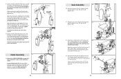
... Weight (22). Do not tighten the Locknuts yet. 7. The Lat Bar (not shown) or the Handle Strap (91) can be attached between the Weight Guides (21) with two Cable Clips. Always engage the Lock Plate (73) when using the low pulley station, engage the Leg Lever Pin (38) into the Front Leg (7) and the Lock Plate (73). 38 8 73 7 17 6. Note: Due to adjust the weight...
... Weight (22). Do not tighten the Locknuts yet. 7. The Lat Bar (not shown) or the Handle Strap (91) can be attached between the Weight Guides (21) with two Cable Clips. Always engage the Lock Plate (73) when using the low pulley station, engage the Leg Lever Pin (38) into the Front Leg (7) and the Lock Plate (73). 38 8 73 7 17 6. Note: Due to adjust the weight...
Instruction Manual
Page 9
... slack in steps 2-7. 62 82 17 Bracket Arm Assembly 9. The use of the remaining parts will need to the brackets on page 20 of the cables does not move smoothly around the pulleys. IMPORTANT: If the cables are inside the Shroud. 62 82 Tighten the Nylon Locknuts (56, 58) used . Attach the Shroud (17) to the Top Frame (4) with 8 two M6 x 16mm Screws (62...
... slack in steps 2-7. 62 82 17 Bracket Arm Assembly 9. The use of the remaining parts will need to the brackets on page 20 of the cables does not move smoothly around the pulleys. IMPORTANT: If the cables are inside the Shroud. 62 82 Tighten the Nylon Locknuts (56, 58) used . Attach the Shroud (17) to the Top Frame (4) with 8 two M6 x 16mm Screws (62...
Instruction Manual
Page 10
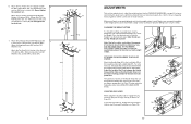
.... Attach the Cable to the Upright (3) with the Bolt and an M10 Nylon Locknut (56). Insert the Leg Lever Pin through the Front Leg (7). Grease an M10 x 85mm Bolt (67) and two Arm Bushings (44). Make sure that the Cable can pivot easily around the Bolt. 10 58 39 54 Grease 65 Seat Assembly 30 30. Slide the Large Foam Pad onto the Right Arm (9). Press a 50mm...
.... Attach the Cable to the Upright (3) with the Bolt and an M10 Nylon Locknut (56). Insert the Leg Lever Pin through the Front Leg (7). Grease an M10 x 85mm Bolt (67) and two Arm Bushings (44). Make sure that the Cable can pivot easily around the Bolt. 10 58 39 54 Grease 65 Seat Assembly 30 30. Slide the Large Foam Pad onto the Right Arm (9). Press a 50mm...

Instruction Manual
Page 11
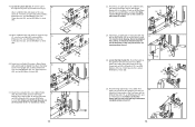
... Cable Trap is removed from the cables. 84 Tighten the M12 Nut (84) against the Large Washer (85). 85 24 14 14. Wrap the High Cable (55) under a 90mm Pulley 15 (48). Attach the Pulley and two Half Finger Guards (43) to the Upright (3) with the Bolt and an M8 Nylon Locknut (58). Route the Arm Cable (54) over a "V"-pulley (46). 14 Attach the "V"-pulley, a Large Cable...
... Cable Trap is removed from the cables. 84 Tighten the M12 Nut (84) against the Large Washer (85). 85 24 14 14. Wrap the High Cable (55) under a 90mm Pulley 15 (48). Attach the Pulley and two Half Finger Guards (43) to the Upright (3) with the Bolt and an M8 Nylon Locknut (58). Route the Arm Cable (54) over a "V"-pulley (46). 14 Attach the "V"-pulley, a Large Cable...
Instruction Manual
Page 12
... the outside of the Leg Lever (8), over the Low Cable (53), with an M10 x 46mm Bolt (81) and an M10 Nylon Locknut (56). Route the Low Cable (53) under a 90mm Pulley 20 (48) and through the Upright (3). Route the High Cable (55) over a 90mm Pulley (48). Attach the Pulley and two Half Finger...52 48 7 53 57 52 71 20. Locate the Low Cable (53). Attach a 90mm Pulley (48) inside of the Front Leg 19 (7), over a 90mm Pulley (48). See the inset drawing. Route the Low Cable (53) over the Low Cable (53), with an M10 x 67mm Bolt (71), an M10 Washer (57), and ...
... the outside of the Leg Lever (8), over the Low Cable (53), with an M10 x 46mm Bolt (81) and an M10 Nylon Locknut (56). Route the Low Cable (53) under a 90mm Pulley 20 (48) and through the Upright (3). Route the High Cable (55) over a 90mm Pulley (48). Attach the Pulley and two Half Finger...52 48 7 53 57 52 71 20. Locate the Low Cable (53). Attach a 90mm Pulley (48) inside of the Front Leg 19 (7), over a 90mm Pulley (48). See the inset drawing. Route the Low Cable (53) over the Low Cable (53), with an M10 x 67mm Bolt (71), an M10 Washer (57), and ...
Instruction Manual
Page 13
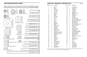
... 86 1 M10 x 70mm Bolt 87 2 M6 Locknut 88 1 Lock 89 1 Lock Pin 90 1 Chain 91 1 Handle Strap 92 2 Handle Grip # 1 User's Manual # 1 Exercise Guide # 2 Grease Packet # 1 Allen Wrench Note: "#" indicates a non-illustrated part. Specifications are subject to change without notice. PART IDENTIFICATION CHART Refer to the drawings below to identify small parts used in the centre of this manual. Note: Some small parts may have been pre...
... 86 1 M10 x 70mm Bolt 87 2 M6 Locknut 88 1 Lock 89 1 Lock Pin 90 1 Chain 91 1 Handle Strap 92 2 Handle Grip # 1 User's Manual # 1 Exercise Guide # 2 Grease Packet # 1 Allen Wrench Note: "#" indicates a non-illustrated part. Specifications are subject to change without notice. PART IDENTIFICATION CHART Refer to the drawings below to identify small parts used in the centre of this manual. Note: Some small parts may have been pre...
Instruction Manual
Page 14
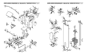
... 89 30 30 27 27 27 57 27 57 56 21 56 21 57 57 82 82 62 62 19 19 2 2 30 30 EXPLODED DRAWING A-Model No. WEEVSY1975.0 R0805A 56 36 36 56 5 5 69 69 67 79 79 35 35 36 36 57 57 56 56 65 65 66 44 66... 48 56 56 71 71 43 43 71 71 43 43 81 81 30 30 78 34 78 34 30 78 30 78 EXPLODED DRAWING B-Model No.
... 89 30 30 27 27 27 57 27 57 56 21 56 21 57 57 82 82 62 62 19 19 2 2 30 30 EXPLODED DRAWING A-Model No. WEEVSY1975.0 R0805A 56 36 36 56 5 5 69 69 67 79 79 35 35 36 36 57 57 56 56 65 65 66 44 66... 48 56 56 71 71 43 43 71 71 43 43 81 81 30 30 78 34 78 34 30 78 30 78 EXPLODED DRAWING B-Model No.


