
Canadian English Manual
Page 2
...size. Apply the decal in the location shown. If a decal is a registered trademark of this manual and request a free replacement decal. WEIDER is missing or illegible, see the front cover of ICON IP, Inc. 2 TABLE OF CONTENTS WARNING DECAL PLACEMENT 2 IMPORTANT PRECAUTIONS 3 ...BEFORE YOU BEGIN 4 PART IDENTIFICATION CHART 5 ASSEMBLY 6 ADJUSTMENT 18 WEIGHT RESISTANCE CHART 20 CABLE DIAGRAM 21 MAINTENANCE 22 EXERCISE GUIDELINES 23 PART LIST 25 EXPLODED DRAWING 26 ORDERING REPLACEMENT PARTS...
...size. Apply the decal in the location shown. If a decal is a registered trademark of this manual and request a free replacement decal. WEIDER is missing or illegible, see the front cover of ICON IP, Inc. 2 TABLE OF CONTENTS WARNING DECAL PLACEMENT 2 IMPORTANT PRECAUTIONS 3 ...BEFORE YOU BEGIN 4 PART IDENTIFICATION CHART 5 ASSEMBLY 6 ADJUSTMENT 18 WEIGHT RESISTANCE CHART 20 CABLE DIAGRAM 21 MAINTENANCE 22 EXERCISE GUIDELINES 23 PART LIST 25 EXPLODED DRAWING 26 ORDERING REPLACEMENT PARTS...
Canadian English Manual
Page 4
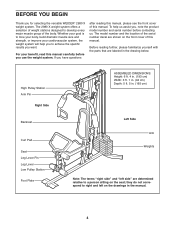
... cover of this manual. High Pulley Station Arm Pin Right Side Backrest Curl Pad Seat Leg Lever Pin Leg Lever Low Pulley Station Foot Plate ASSEMBLED DIMENSIONS: Height: 6 ft. 4 in. (193 cm) Width: 3 ft. 1 in. (94 cm) Depth: 5 ft. 5 in. (165 cm) Left Side Arm Weights Note: The... terms "right side" and "left on the drawings in the drawing below. If you for selecting the versatile WEIDER® 2980 X weight system. Before reading further, please familiarize yourself with the parts that are determined relative to achieve the specific results you use the ...
... cover of this manual. High Pulley Station Arm Pin Right Side Backrest Curl Pad Seat Leg Lever Pin Leg Lever Low Pulley Station Foot Plate ASSEMBLED DIMENSIONS: Height: 6 ft. 4 in. (193 cm) Width: 3 ft. 1 in. (94 cm) Depth: 5 ft. 5 in. (165 cm) Left Side Arm Weights Note: The... terms "right side" and "left on the drawings in the drawing below. If you for selecting the versatile WEIDER® 2980 X weight system. Before reading further, please familiarize yourself with the parts that are determined relative to achieve the specific results you use the ...
Canadian English Manual
Page 5
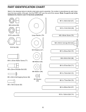
... small parts used in parentheses by each drawing is not in the hardware kit, check to see if it has been preattached. The number in assembly. Note: If a part is the key number of the part, from the PART LIST near the end of this manual. M8 Locknut (58) M10 x 46mm...
... small parts used in parentheses by each drawing is not in the hardware kit, check to see if it has been preattached. The number in assembly. Note: If a part is the key number of the part, from the PART LIST near the end of this manual. M8 Locknut (58) M10 x 46mm...
Canadian English Manual
Page 6
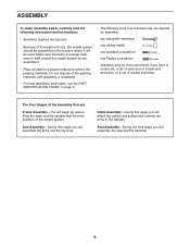
..., use the PART IDENTIFICATION CHART on page 5. • The following information and instructions: • Assembly requires two persons. • Because of its weight and size, the weight system should be assembled in the location where it . • Place all parts in a cleared area and remove the ... will be more convenient if you will begin by assembling the base and the uprights that form the skeleton of the weight system. The Four Stages of the Assembly Process Frame Assembly-You will assemble the seat and the backrest. 6 Seat Assembly-During the final stage you have a socket set,...
..., use the PART IDENTIFICATION CHART on page 5. • The following information and instructions: • Assembly requires two persons. • Because of its weight and size, the weight system should be assembled in the location where it . • Place all parts in a cleared area and remove the ... will be more convenient if you will begin by assembling the base and the uprights that form the skeleton of the weight system. The Four Stages of the Assembly Process Frame Assembly-You will assemble the seat and the backrest. 6 Seat Assembly-During the final stage you have a socket set,...
Canadian English Manual
Page 7
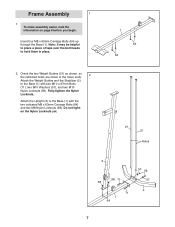
... Base (1) with the two indicated M8 x 63mm Carriage Bolts (64) and two M8 Nylon Locknuts (58). Attach the Upright (3) to hold them in place. 2. Frame Assembly 1 1. Note: It may be helpful to place a piece of tape over the bolt heads to the Base (1) with two M10 x 67mm Bolts (71), two M10... 71 58 71 1 64 57 56 57 2 7 Fully tighten the Nylon Locknuts. Insert four M8 x 63mm Carriage Bolts (64) up through the Base (1). To make assembly easier, read the information on page 6 before you begin.
... Base (1) with the two indicated M8 x 63mm Carriage Bolts (64) and two M8 Nylon Locknuts (58). Attach the Upright (3) to hold them in place. 2. Frame Assembly 1 1. Note: It may be helpful to place a piece of tape over the bolt heads to the Base (1) with two M10 x 67mm Bolts (71), two M10... 71 58 71 1 64 57 56 57 2 7 Fully tighten the Nylon Locknuts. Insert four M8 x 63mm Carriage Bolts (64) up through the Base (1). To make assembly easier, read the information on page 6 before you begin.

Canadian English Manual
Page 9
... 3 Grease 69 40 6. Tighten the M8 Nylon Locknuts (58). 59 4 68 59 76 76 56 57 57 74 Welded Support 58 58 3 21 21 Arm Assembly 7. Do not overtighten the Nylon Locknut; the Pivot Frame must pivot easily. 7 56 8 Welded Support 7 Grease 79 8. Orient the Leg Lever (8) with the welded support...
... 3 Grease 69 40 6. Tighten the M8 Nylon Locknuts (58). 59 4 68 59 76 76 56 57 57 74 Welded Support 58 58 3 21 21 Arm Assembly 7. Do not overtighten the Nylon Locknut; the Pivot Frame must pivot easily. 7 56 8 Welded Support 7 Grease 79 8. Orient the Leg Lever (8) with the welded support...

Canadian English Manual
Page 10
... 9 Bolt and an M10 Nylon Locknut (56). the Right Arm must pivot easily. Attach the Cable to the Pivot Frame (5) in the same way. 10. Assemble the Right Arm (9) in the same way. 9 66 Grease 39 56 10 11 42 57 77 57 Grease 9 44 67 5 44 57 Grease 57 10... 56 Cable Assembly 11 11. See the CABLE DIAGRAM on the Shoulder Bolt. 10 58 39 54 Grease 65 Do not overtighten the Nylon Locknut; Attach the Left...
... 9 Bolt and an M10 Nylon Locknut (56). the Right Arm must pivot easily. Attach the Cable to the Pivot Frame (5) in the same way. 10. Assemble the Right Arm (9) in the same way. 9 66 Grease 39 56 10 11 42 57 77 57 Grease 9 44 67 5 44 57 Grease 57 10... 56 Cable Assembly 11 11. See the CABLE DIAGRAM on the Shoulder Bolt. 10 58 39 54 Grease 65 Do not overtighten the Nylon Locknut; Attach the Left...
Canadian English Manual
Page 16
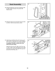
... the Backrest (16) to the Front Leg (7) with two M6 x 63mm Screws (70) and two M6 16 Washers (80). 3 70 80 80 70 29. Seat Assembly 28 28.
... the Backrest (16) to the Front Leg (7) with two M6 x 63mm Screws (70) and two M6 16 Washers (80). 3 70 80 80 70 29. Seat Assembly 28 28.

Canadian English Manual
Page 21
...) Length: 10 ft. 8 in each drawing show the proper route of the cables. Make sure that the cables, cable traps, pulleys, and guards are not assembled correctly, the weight system will not function properly and damage may occur. CABLE DIAGRAM The diagram below shows the proper routing of that cable. The... in . (325 cm) 21 Use the diagram to make sure that the cable traps do not touch or bind the cables. If the cables are assembled correctly.
...) Length: 10 ft. 8 in each drawing show the proper route of the cables. Make sure that the cables, cable traps, pulleys, and guards are not assembled correctly, the weight system will not function properly and damage may occur. CABLE DIAGRAM The diagram below shows the proper routing of that cable. The... in . (325 cm) 21 Use the diagram to make sure that the cable traps do not touch or bind the cables. If the cables are assembled correctly.


