
Service Manual
Page 2
Specifications 3. Trouble Shooting 10. Spare parts list 12. Assembly Explosion Drawing Block Diagram PAGE 1-1 2-1 3-1 4-1 5-1 6-1 7-1 8-1 9-1 10-1 11-1 12-1 VIZIO VP50HDTV10A HDTV Service Manual Pin Assignment 6. Complete Parts List Appendix 1. Main Board PCB Layout 3. Factory Preset Timings 5. On Screen Display 4. Waveforms 9. Block Diagram 11. Main Board I/O Connections 7. Main Board Circuit Diagram 2. Theory of Contents CONTENTS Sections 1. Table of Circuit Operation 8. Features 2.
Specifications 3. Trouble Shooting 10. Spare parts list 12. Assembly Explosion Drawing Block Diagram PAGE 1-1 2-1 3-1 4-1 5-1 6-1 7-1 8-1 9-1 10-1 11-1 12-1 VIZIO VP50HDTV10A HDTV Service Manual Pin Assignment 6. Complete Parts List Appendix 1. Main Board PCB Layout 3. Factory Preset Timings 5. On Screen Display 4. Waveforms 9. Block Diagram 11. Main Board I/O Connections 7. Main Board Circuit Diagram 2. Theory of Contents CONTENTS Sections 1. Table of Circuit Operation 8. Features 2.

Service Manual
Page 3
... are registered trademarks of Video Electronics Standards Association (VESA). However, there is encouraged to try to "Electromagnetic compatibility." Always use a grounded power supply cord and the provided shielded video interface cable with the instructions, may be held responsible for any unauthorized changes or modifications to Amtrak products will not occur in accordance with bonded ferrite cores. Canada (CSA); Service Manual VIZIO VP50HDTV10A IBM and IBM...
... are registered trademarks of Video Electronics Standards Association (VESA). However, there is encouraged to try to "Electromagnetic compatibility." Always use a grounded power supply cord and the provided shielded video interface cable with the instructions, may be held responsible for any unauthorized changes or modifications to Amtrak products will not occur in accordance with bonded ferrite cores. Canada (CSA); Service Manual VIZIO VP50HDTV10A IBM and IBM...
Service Manual
Page 4
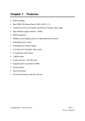
... 1-1 File No. SG-0219 HDMI y HDCP supportive y Multiple-screen display (picture-on-picture/picture-in-picture) y Selectable picture mode y 3-language On Screen Display y 2 S-video and Composite video inputs y 2 Component video inputs y 2 HDMI inputs y 6 audio stereos, 1 PC Mini-Jack y Supporting DVI converted to HDMI y Closed caption y Gloss front bezel y The thinnest model of this size: 99 mm CONFIDENTIAL - Chapter 1 Features y Wall-mountable y New WIDE HD Plasma Panel:1366 x 768 (H x V) y TruSurround XT sound system and DCDi by Faroujia video image y High definition digital interface -
... 1-1 File No. SG-0219 HDMI y HDCP supportive y Multiple-screen display (picture-on-picture/picture-in-picture) y Selectable picture mode y 3-language On Screen Display y 2 S-video and Composite video inputs y 2 Component video inputs y 2 HDMI inputs y 6 audio stereos, 1 PC Mini-Jack y Supporting DVI converted to HDMI y Closed caption y Gloss front bezel y The thinnest model of this size: 99 mm CONFIDENTIAL - Chapter 1 Features y Wall-mountable y New WIDE HD Plasma Panel:1366 x 768 (H x V) y TruSurround XT sound system and DCDi by Faroujia video image y High definition digital interface -
Service Manual
Page 9
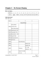
... Chapter 3 On Screen Display Main unit button Buttons 1 Name 2 3 4 5 6 7 MENU CH+/▲ CH-/▼ VOL+/► VOL-/◄ INPUT OSD Adjustment Main OSD Tree Mode Image Settings Picture Mode VIDEO (Custom,vivid, Movie,Game,Sport) VIDEO Brightness(0~100) VIDEO Contrast(O~100) VIDEO Saturation(0〜100) VIDEO Hue(-50~50) VIDEO Sharpness(0~24) VIDEO Advanced VIDEO Noise Reduction VIDEO Motion(0~16) VIDEO Digital(0~64) VIDEO Fleshtone Off﹑High、 Moderate、Low VIDEO Dynamic Contrast (0,1,2,3) CONFIDENTIAL...
... Chapter 3 On Screen Display Main unit button Buttons 1 Name 2 3 4 5 6 7 MENU CH+/▲ CH-/▼ VOL+/► VOL-/◄ INPUT OSD Adjustment Main OSD Tree Mode Image Settings Picture Mode VIDEO (Custom,vivid, Movie,Game,Sport) VIDEO Brightness(0~100) VIDEO Contrast(O~100) VIDEO Saturation(0〜100) VIDEO Hue(-50~50) VIDEO Sharpness(0~24) VIDEO Advanced VIDEO Noise Reduction VIDEO Motion(0~16) VIDEO Digital(0~64) VIDEO Fleshtone Off﹑High、 Moderate、Low VIDEO Dynamic Contrast (0,1,2,3) CONFIDENTIAL...

Service Manual
Page 10
Mode VIDEO Custom Color VIDEO VIDEO VIDEO PC PC PC PC PC PC PC PC PC PC PC PC VIDEO Aspect Ratio PC Aspect Ratio PIP Red(0~100) Green(0〜100) Blue(0~100) Auto Adjustment lmage Position Phase CIocks/Line Color Temp Warm(5400K) Standard(6500K) Cool(9300K) User Red(0~100) Green(0〜100) Blue(0~100) Display Settings 16:9、4:3、Zoom、 Panoramic* 16:9、4:3 PIP Mode PIP Position Off, Large PIP, Small PIP, POP Top-Left, CONFIDENTIAL - DO NOT COPY Page 3-2 File No. SG-0219
Mode VIDEO Custom Color VIDEO VIDEO VIDEO PC PC PC PC PC PC PC PC PC PC PC PC VIDEO Aspect Ratio PC Aspect Ratio PIP Red(0~100) Green(0〜100) Blue(0~100) Auto Adjustment lmage Position Phase CIocks/Line Color Temp Warm(5400K) Standard(6500K) Cool(9300K) User Red(0~100) Green(0〜100) Blue(0~100) Display Settings 16:9、4:3、Zoom、 Panoramic* 16:9、4:3 PIP Mode PIP Position Off, Large PIP, Small PIP, POP Top-Left, CONFIDENTIAL - DO NOT COPY Page 3-2 File No. SG-0219

Service Manual
Page 18
Password DTV Menu White Green Blue Red Cyan Yellow Magenta (7)Window Opacity Solid Translucent Transparent Channel Block * HDMI and Component 720P/1080i inputs do not support Panoramic. **See below for detailed information regarding the PIP sources. Parental control C. SG-0219 DO NOT COPY Page 3-10 File No. CONFIDENTIAL -
Password DTV Menu White Green Blue Red Cyan Yellow Magenta (7)Window Opacity Solid Translucent Transparent Channel Block * HDMI and Component 720P/1080i inputs do not support Panoramic. **See below for detailed information regarding the PIP sources. Parental control C. SG-0219 DO NOT COPY Page 3-10 File No. CONFIDENTIAL -

Service Manual
Page 19
... input priority scheme applies to AV2. *** When Speakers off **** Do Scan or Manual Scan function, it maybe spend several minutes is connected to AV1 S-Video and AV1 Video simultaneously, then S-Video will be the only choice for PIP and POP modes. (2) For AV1 and AV2, S-Video has priority. If a signal is connected to AV1 S-Video by itself or signals are available for AV1. It depends on channels...
... input priority scheme applies to AV2. *** When Speakers off **** Do Scan or Manual Scan function, it maybe spend several minutes is connected to AV1 S-Video and AV1 Video simultaneously, then S-Video will be the only choice for PIP and POP modes. (2) For AV1 and AV2, S-Video has priority. If a signal is connected to AV1 S-Video by itself or signals are available for AV1. It depends on channels...

Service Manual
Page 21
BOARD PICTURE MAIN BOARD CONFIDENTIAL - SG-0219 PCB PARTS NAME/NUMBER AND FUNCTION DESCRIPTION PART NAME PART NUMBER POWER SUPPLY BOARD X DRIVER BOARD Y DRIVER BOARD AUDIO POWER SELECTOR MAIN BOARD 385001020150 IR BOARD DISPLAY BOARD ATSC BOARD 385000220189 385000220156 385000120187 FUNCTION DESCRIPTION PROVIDE ALL THE POWER FOR TV SET X ELECTRODE DRIVING BOARD Y ELECTRODE DRIVING BOARD AUDIO POWER SUPPLY(+30V OR +24V) CONNECTING TO TRANSFER DISPLY SIGNAL TO PDP SET, AMPLIFIER THE AUDIO SIGNAL TO THE SPEAKER RECEIVE THE REMOTE CONTROLER AND DISPLAY SYSTEM STATUS LED KEYPAD ...
BOARD PICTURE MAIN BOARD CONFIDENTIAL - SG-0219 PCB PARTS NAME/NUMBER AND FUNCTION DESCRIPTION PART NAME PART NUMBER POWER SUPPLY BOARD X DRIVER BOARD Y DRIVER BOARD AUDIO POWER SELECTOR MAIN BOARD 385001020150 IR BOARD DISPLAY BOARD ATSC BOARD 385000220189 385000220156 385000120187 FUNCTION DESCRIPTION PROVIDE ALL THE POWER FOR TV SET X ELECTRODE DRIVING BOARD Y ELECTRODE DRIVING BOARD AUDIO POWER SUPPLY(+30V OR +24V) CONNECTING TO TRANSFER DISPLY SIGNAL TO PDP SET, AMPLIFIER THE AUDIO SIGNAL TO THE SPEAKER RECEIVE THE REMOTE CONTROLER AND DISPLAY SYSTEM STATUS LED KEYPAD ...

Service Manual
Page 25
...power cord Yes No Power LED is high? (Display_ON) Remove R87. No No Check W1 pin 27 is lighting? No U13 fail Yes No Power LED is lighting? Check component 1 No (Y signal) ÎC252 Is there sync? Is there any OSD's logo No Check input source Check internal cable? 1.LVDS cable. Is AD14 high? Does scaler detect the signal? Check internal cable? 1.CN1's cable 2.CN3's cable No Check main board... 7,8 = +12V No Yes Panel power fail No Fuse fail D10,D11 LED is lighting? DO NOT COPY Page 9-6 File No. PDP DISPLAY NOTHING(Analog HD1/AC on screen? Yes No Check U3.4Î...
...power cord Yes No Power LED is high? (Display_ON) Remove R87. No No Check W1 pin 27 is lighting? No U13 fail Yes No Power LED is lighting? Check component 1 No (Y signal) ÎC252 Is there sync? Is there any OSD's logo No Check input source Check internal cable? 1.LVDS cable. Is AD14 high? Does scaler detect the signal? Check internal cable? 1.CN1's cable 2.CN3's cable No Check main board... 7,8 = +12V No Yes Panel power fail No Fuse fail D10,D11 LED is lighting? DO NOT COPY Page 9-6 File No. PDP DISPLAY NOTHING(Analog HD1/AC on screen? Yes No Check U3.4Î...

Service Manual
Page 26
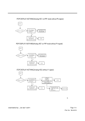
... component 1 No (Y signal) =>C255 Is there sync? Trace componect 1 from Input To U13 circuit Check R204,R201 Yes Use GProbe connect No from main to PC. Trace componect 1 from Input To U10 circuit Check R193,R191 Yes Use GProbe connect No from main to PC. U13 fail PDP DISPLAY NOTHING(Analog HD1 without Pr signal) BLOCK 1 No Is picture on screen? Does scaler...
... component 1 No (Y signal) =>C255 Is there sync? Trace componect 1 from Input To U13 circuit Check R204,R201 Yes Use GProbe connect No from main to PC. Trace componect 1 from Input To U10 circuit Check R193,R191 Yes Use GProbe connect No from main to PC. U13 fail PDP DISPLAY NOTHING(Analog HD1 without Pr signal) BLOCK 1 No Is picture on screen? Does scaler...
Service Manual
Page 27
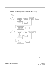
... 13 Input clamp voltageÎpin 3(+5V) Output clamp voltageÎpin 32(+5V) VCC3Îpin 22,23(+5V) Input_switch_selectÎhigh(+5V) U23 fail Use GProbe connect No from main to PC. DO NOT COPY Page 9-8 File No. PDP DISPLAY NOTHING(Analog HD1 on PIP mode without Y signal) BLOCK 1 Is picture on screen? U10 fail PDP DISPLAY NOTHING(Analog HD1 on PIP mode...
... 13 Input clamp voltageÎpin 3(+5V) Output clamp voltageÎpin 32(+5V) VCC3Îpin 22,23(+5V) Input_switch_selectÎhigh(+5V) U23 fail Use GProbe connect No from main to PC. DO NOT COPY Page 9-8 File No. PDP DISPLAY NOTHING(Analog HD1 on PIP mode without Y signal) BLOCK 1 Is picture on screen? U10 fail PDP DISPLAY NOTHING(Analog HD1 on PIP mode...

Service Manual
Page 28
... 3(+5V) Output clamp voltageÎpin 32(+5V) VCC3Îpin 22,23(+5V) Input_switch_selectÎhigh(+5V) U24 fail Use GProbe connect No from main to PC. U10 fail Yes Check before U23's circuit No 1.C256,C261(AC coupled) 2.R215 Input source fail 3.R218(75ohm) PDP DISPLAY NOTHING(Analog HD2 on PIP mode without Y signal) BLOCK 1 Is picture on screen? DO...
... 3(+5V) Output clamp voltageÎpin 32(+5V) VCC3Îpin 22,23(+5V) Input_switch_selectÎhigh(+5V) U24 fail Use GProbe connect No from main to PC. U10 fail Yes Check before U23's circuit No 1.C256,C261(AC coupled) 2.R215 Input source fail 3.R218(75ohm) PDP DISPLAY NOTHING(Analog HD2 on PIP mode without Y signal) BLOCK 1 Is picture on screen? DO...

Service Manual
Page 29
...,C290(AC coupled) 2.R211 Input source fail 3.R217(75ohm) PDP DISPLAY NOTHING(Analog HD2 on PIP mode without Pb signal) BLOCK 1 No Is no red color on screen? U10 fail Yes Check before U24's circuit No 1.C276,C281(AC coupled) 2.R215 Input source fail 3.R218(75ohm) PDP DISPLAY NOTHING(RGB) BLOCK 1 No Is picture on screen? Check U45 H sync output Î U45 pin4,R181 No V sync output Î U45 pin8...
...,C290(AC coupled) 2.R211 Input source fail 3.R217(75ohm) PDP DISPLAY NOTHING(Analog HD2 on PIP mode without Pb signal) BLOCK 1 No Is no red color on screen? U10 fail Yes Check before U24's circuit No 1.C276,C281(AC coupled) 2.R215 Input source fail 3.R218(75ohm) PDP DISPLAY NOTHING(RGB) BLOCK 1 No Is picture on screen? Check U45 H sync output Î U45 pin4,R181 No V sync output Î U45 pin8...

Service Manual
Page 31
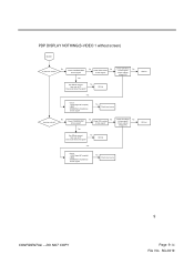
.... No Check input source PDP DISPLAY NOTHING(Composite 1 on PIP without screen) BLOCK 1 No Is picture on screen? No Is picture on screen? Check collector voltage(+5V). No Is there signal? Does scaler detect the signal? SG-0219 Yes No No Check Q28's emitter. Yes Use GProbe connect No from main to PC. PDP DISPLAY NOTHING(Composite 1 without screen) BLOCK 1 No No No Check Q28's Base. Check Q28...
.... No Check input source PDP DISPLAY NOTHING(Composite 1 on PIP without screen) BLOCK 1 No Is picture on screen? No Is picture on screen? Check collector voltage(+5V). No Is there signal? Does scaler detect the signal? SG-0219 Yes No No Check Q28's emitter. Yes Use GProbe connect No from main to PC. PDP DISPLAY NOTHING(Composite 1 without screen) BLOCK 1 No No No Check Q28's Base. Check Q28...

Service Manual
Page 32
... there signal? No Check input source CONFIDENTIAL - DO NOT COPY 8 Page 9-13 File No. Use GProbe connect No from main to PC. No Check input source PDP DISPLAY NOTHING(Composite 2 on screen? PDP DISPLAY NOTHING(Composite 2 without screen) BLOCK 1 No Is picture on PIP without screen) BLOCK 1 No No No Check Q29's Base. Yes Use GProbe connect No from main to PC. Check Q29's Base. Is there signal? No Is picture on screen...
... there signal? No Check input source CONFIDENTIAL - DO NOT COPY 8 Page 9-13 File No. Use GProbe connect No from main to PC. No Check input source PDP DISPLAY NOTHING(Composite 2 on screen? PDP DISPLAY NOTHING(Composite 2 without screen) BLOCK 1 No Is picture on PIP without screen) BLOCK 1 No No No Check Q29's Base. Yes Use GProbe connect No from main to PC. Check Q29's Base. Is there signal? No Is picture on screen...
Service Manual
Page 33
... signal? Does scaler detect the signal? No No No Check Q31's Base. No Check input source Q31 fail CONFIDENTIAL - Check Q30's Base. No Check C328,R308,R307 Check Q31's emitter. Is there signal? PDP DISPLAY NOTHING(S-VIDEO 1 without screen) BLOCK 1 No Is picture on screen? Yes No No Check Q30's emitter. Check collector voltage(+5V). Is there signal? Check collector voltage(+5V). Yes Use GProbe connect...
... signal? Does scaler detect the signal? No No No Check Q31's Base. No Check input source Q31 fail CONFIDENTIAL - Check Q30's Base. No Check C328,R308,R307 Check Q31's emitter. Is there signal? PDP DISPLAY NOTHING(S-VIDEO 1 without screen) BLOCK 1 No Is picture on screen? Yes No No Check Q30's emitter. Check collector voltage(+5V). Is there signal? Check collector voltage(+5V). Yes Use GProbe connect...
Service Manual
Page 34
...(75ohm impedance) Is there signal? Is there signal? No Check input source No No No Check Q31's Base. Check collector voltage(+5V). Check Q30's Base. Does scaler detect the signal? SG-0219 DO NOT COPY 10 Page 9-15 File No. PDP DISPLAY NOTHING(S-VIDEO 1 on PIP mode without screen) BLOCK 1 No Is picture on screen? No Is there signal? Yes Use GProbe connect No from main to PC...
...(75ohm impedance) Is there signal? Is there signal? No Check input source No No No Check Q31's Base. Check collector voltage(+5V). Check Q30's Base. Does scaler detect the signal? SG-0219 DO NOT COPY 10 Page 9-15 File No. PDP DISPLAY NOTHING(S-VIDEO 1 on PIP mode without screen) BLOCK 1 No Is picture on screen? No Is there signal? Yes Use GProbe connect No from main to PC...

Service Manual
Page 35
...'s Base. Is there signal? Yes Use GProbe connect No from main to PC. DO NOT COPY 11 Page 9-16 File No. PDP DISPLAY NOTHING(S-VIDEO 2 without screen) BLOCK 1 No Is picture on screen? Check C332,R316,R320 Is there signal? Is there signal? Does scaler detect the signal? No Check C336,R319,R318 Check Q32's emitter. Check collector voltage(+5V). No Check input source Q32...
...'s Base. Is there signal? Yes Use GProbe connect No from main to PC. DO NOT COPY 11 Page 9-16 File No. PDP DISPLAY NOTHING(S-VIDEO 2 without screen) BLOCK 1 No Is picture on screen? Check C332,R316,R320 Is there signal? Is there signal? Does scaler detect the signal? No Check C336,R319,R318 Check Q32's emitter. Check collector voltage(+5V). No Check input source Q32...

Service Manual
Page 36
... Check Q32's Base. Is there signal? PDP DISPLAY NOTHING(S-VIDEO 2 on PIP mode without screen) BLOCK 1 No Is picture on screen? Is there signal? Check collector voltage(+5V). U10 fail Yes Check: 1.C333 (signal AC coupled) 2.R301 3.R303(75ohm impedance) Is there signal? U10 fail Yes Check: 1.C335 (signal AC coupled) 2.R300 3.R302(75ohm impedance) Is there signal? Is there signal? No Check input source Q32 fail CONFIDENTIAL...
... Check Q32's Base. Is there signal? PDP DISPLAY NOTHING(S-VIDEO 2 on PIP mode without screen) BLOCK 1 No Is picture on screen? Is there signal? Check collector voltage(+5V). U10 fail Yes Check: 1.C333 (signal AC coupled) 2.R301 3.R303(75ohm impedance) Is there signal? U10 fail Yes Check: 1.C335 (signal AC coupled) 2.R300 3.R302(75ohm impedance) Is there signal? Is there signal? No Check input source Q32 fail CONFIDENTIAL...

Service Manual
Page 37
... SCLÎPin 6 SDAÎpin 5 Check U37 power 5VÎPin 8 No No Check D66 and D65 Are there 5V output? DO NOT COPY 14 Page 9-18 File No. No Check U35 pin 90 Î high No V syncÎR419 H syncÎR420 clockÎR421 Check +3.3V_SWÎ Yes...40 Yes Yes Check U35 all power Check Q44 No GataÎhigh(5V) No I2C addr.ÎR424 U35 fail Q44 fail Check Block 2 No Is picture color ok? D66 fail or D65 fail Is picture on screen? PDP DISPLAY NOTHING(Digital 2 U35 with PORT B without screen) BLOCK 1 No Is picture on screen? Check input source? Check U35's RGB data bus...
... SCLÎPin 6 SDAÎpin 5 Check U37 power 5VÎPin 8 No No Check D66 and D65 Are there 5V output? DO NOT COPY 14 Page 9-18 File No. No Check U35 pin 90 Î high No V syncÎR419 H syncÎR420 clockÎR421 Check +3.3V_SWÎ Yes...40 Yes Yes Check U35 all power Check Q44 No GataÎhigh(5V) No I2C addr.ÎR424 U35 fail Q44 fail Check Block 2 No Is picture color ok? D66 fail or D65 fail Is picture on screen? PDP DISPLAY NOTHING(Digital 2 U35 with PORT B without screen) BLOCK 1 No Is picture on screen? Check input source? Check U35's RGB data bus...


