Service Manual
Page 2
..., transcribed, stored in a retrieval system, or translated into any language or computer language, in the contents hereof without the prior written permission of ViewSonic Corporation. Sears ii VE150(b)-2 Service Manual Disclaimer ViewSonic makes no representations or warranties, either expressed or implied, with respect to notify any person of such revision or changes. DCN1648 Approval T. Further...
..., transcribed, stored in a retrieval system, or translated into any language or computer language, in the contents hereof without the prior written permission of ViewSonic Corporation. Sears ii VE150(b)-2 Service Manual Disclaimer ViewSonic makes no representations or warranties, either expressed or implied, with respect to notify any person of such revision or changes. DCN1648 Approval T. Further...
Service Manual
Page 3
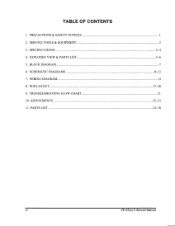
SERVICE TOOLS & EQUIPMENT 3. SPECIFICATIONS 4. BLOCK DIAGRAM 6. EXPLODED VIEW & PARTS LIST 5. WIRING DIAGRAM 8. TABLE OF CONTENTS 1. TROUBLESHOOTING FLOW CHART 10. SCHEMATIC DIAGRAMS 7. PCB LAYOUT 9. PARTS LIST 1 2 2-4 5-6 7 8-13 14 1720 21 22-23 24-30 iii VE150(b)-2 Service Manual PRECAUTIONS & SAFETY NOTICES 2. ADJUSTMENTS 11.
SERVICE TOOLS & EQUIPMENT 3. SPECIFICATIONS 4. BLOCK DIAGRAM 6. EXPLODED VIEW & PARTS LIST 5. WIRING DIAGRAM 8. TABLE OF CONTENTS 1. TROUBLESHOOTING FLOW CHART 10. SCHEMATIC DIAGRAMS 7. PCB LAYOUT 9. PARTS LIST 1 2 2-4 5-6 7 8-13 14 1720 21 22-23 24-30 iii VE150(b)-2 Service Manual PRECAUTIONS & SAFETY NOTICES 2. ADJUSTMENTS 11.
Service Manual
Page 4
... not try to repair the monitor your monitor only in this product please refer to reduce interference. 5. If you're unsure of this chassis have the same safety characteristics as to the monitor as well as specified in this guide handy. PRODUCT SAFETY NOTICE Many electrical and mechanical parts in a clean, dry environment. VE150(b)-2 Service Manual 1.
... not try to repair the monitor your monitor only in this product please refer to reduce interference. 5. If you're unsure of this chassis have the same safety characteristics as to the monitor as well as specified in this guide handy. PRODUCT SAFETY NOTICE Many electrical and mechanical parts in a clean, dry environment. VE150(b)-2 Service Manual 1.

Service Manual
Page 6
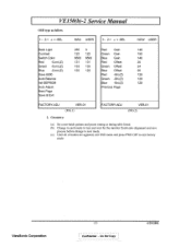
No. No. VE150(b)-2 Service Manual 3.2. No. No. ViewSonic Corporation -3Confidential - ITEM TIMING Pixel Rate H TOTAL H DISPLAY H B-Porch H Width H Border V TOTAL V DISPLAY V B-Porch Vs Width V Border H/V Sync Interlace 6 7 8 9... 2.200us 1.616us 1.118us 2.092us 1.219us 1.200us 0.000us 0.000us 0.000us 0.000us 0.000us 13.333ms 13.417ms 16.666ms 13.328ms 13.346ms 12.800ms 12.552ms 15.880ms 12.795ms 12.749ms 0.448ms 0.784ms 0.600ms 0.466ms 0.498ms 0.064ms 0.060ms 0.124ms 0.050ms 0.050ms 0.000ms 0.00ms 0.000ms 0.000ms 0.000ms +/+ -/- -I ...
No. No. VE150(b)-2 Service Manual 3.2. No. No. ViewSonic Corporation -3Confidential - ITEM TIMING Pixel Rate H TOTAL H DISPLAY H B-Porch H Width H Border V TOTAL V DISPLAY V B-Porch Vs Width V Border H/V Sync Interlace 6 7 8 9... 2.200us 1.616us 1.118us 2.092us 1.219us 1.200us 0.000us 0.000us 0.000us 0.000us 0.000us 13.333ms 13.417ms 16.666ms 13.328ms 13.346ms 12.800ms 12.552ms 15.880ms 12.795ms 12.749ms 0.448ms 0.784ms 0.600ms 0.466ms 0.498ms 0.064ms 0.060ms 0.124ms 0.050ms 0.050ms 0.000ms 0.00ms 0.000ms 0.000ms 0.000ms +/+ -/- -I ...
Service Manual
Page 7
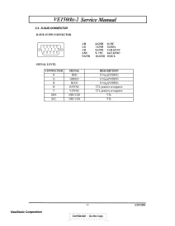
VEl50(b)-2 Service Manual 3.3. D-SUB CONNECTOR D-SUB 15 PIN CONNECTOR \.., 1 2 3 4 5 0 0 6 7 8 9 10 0 0 0 0 0 11 12 13 14 15 0 0000 1.R 2.G 3.B 4.NC 5.GND 6.GND 11.NC 7.GND 12.SDA 8.GND 13.H.SYNC 9. +5V 14.V.SYNC 10.GND 15.SCL SIGNAL LEVEL CONNECTOR R G B H V SDA SCL SIGNAL RED GREEN BLUE H/SYNC V/SYNC DDC1/2B DDC 1 /2B DESCRIPTION 0.7vp-p(VIDEO) 0.7vp-p(VIDEO) 0.7vp-p(VIDEO) TTL positive or negative TTL positive or negative TTL TTL ViewSonic Corporation -4Confidentipt - Do Not Copy 6/29/2001
VEl50(b)-2 Service Manual 3.3. D-SUB CONNECTOR D-SUB 15 PIN CONNECTOR \.., 1 2 3 4 5 0 0 6 7 8 9 10 0 0 0 0 0 11 12 13 14 15 0 0000 1.R 2.G 3.B 4.NC 5.GND 6.GND 11.NC 7.GND 12.SDA 8.GND 13.H.SYNC 9. +5V 14.V.SYNC 10.GND 15.SCL SIGNAL LEVEL CONNECTOR R G B H V SDA SCL SIGNAL RED GREEN BLUE H/SYNC V/SYNC DDC1/2B DDC 1 /2B DESCRIPTION 0.7vp-p(VIDEO) 0.7vp-p(VIDEO) 0.7vp-p(VIDEO) TTL positive or negative TTL positive or negative TTL TTL ViewSonic Corporation -4Confidentipt - Do Not Copy 6/29/2001
Service Manual
Page 9
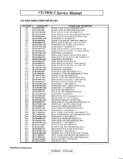
... GRAY INDICATOR JT156E2 POWER LED PMMA 94HB SCREW,BND T+ M3X8(BND T+) NAME PLATE JD144V3 VIEWSONIC 3BIRDS AL METAL FITTG JT166E SECC 1.0t 15'"LCD CPT SCREW,BND+ M3*12 (BND+) WITH NYLOK SCREW,BND T+ M3X8(BND T+) SHIELD PLATE SPTE 0.3 LCD INVERTOR SIDE SHIELD PLATE JT156E SPTE t=0.3 FOR INVERTER SCREW,BND+ M3X6(BND+) INSULATOR JTI66E...+M3X12 NYLOK DUST COVER JT166E HINGE-B ABS 94HB/GY752I DUST COVER HINGE-B ABS 94HB/Midnight GRAY LEG JD144B SBR 9 11.8X5t BLACK HOLDER NYLON 66 ViewSonic Corporation : Confidential - VE150(b)-2 Service Manual 4.2.
... GRAY INDICATOR JT156E2 POWER LED PMMA 94HB SCREW,BND T+ M3X8(BND T+) NAME PLATE JD144V3 VIEWSONIC 3BIRDS AL METAL FITTG JT166E SECC 1.0t 15'"LCD CPT SCREW,BND+ M3*12 (BND+) WITH NYLOK SCREW,BND T+ M3X8(BND T+) SHIELD PLATE SPTE 0.3 LCD INVERTOR SIDE SHIELD PLATE JT156E SPTE t=0.3 FOR INVERTER SCREW,BND+ M3X6(BND+) INSULATOR JTI66E...+M3X12 NYLOK DUST COVER JT166E HINGE-B ABS 94HB/GY752I DUST COVER HINGE-B ABS 94HB/Midnight GRAY LEG JD144B SBR 9 11.8X5t BLACK HOLDER NYLON 66 ViewSonic Corporation : Confidential - VE150(b)-2 Service Manual 4.2.
Service Manual
Page 24
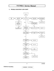
... P005,P006 data bus have signal Yes • Change 1005 LCD controller IC No • Change LCD panel ViewSonic Corporation -21Confidential - Check Keypad OK? Change 1003 Change X001 Yes Check panel Vpn1 No signal P005 pin4,5 is OK? Do Not Copy 6/29/2001 VE150(b)-2 Service Manual 9. V Yes Check P104 pin/ is 3.3V P104 pin2 is 5V...
... P005,P006 data bus have signal Yes • Change 1005 LCD controller IC No • Change LCD panel ViewSonic Corporation -21Confidential - Check Keypad OK? Change 1003 Change X001 Yes Check panel Vpn1 No signal P005 pin4,5 is OK? Do Not Copy 6/29/2001 VE150(b)-2 Service Manual 9. V Yes Check P104 pin/ is 3.3V P104 pin2 is 5V...
Service Manual
Page 25
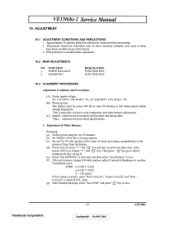
.... (c). ViewSonic Corporation -22Confidential - MAIN ADJUSTMENTS NO. This is needed before starting alignments. ADJUSTMENT 10.1. Adjustments should be allowed for warm up time must be over 30 minutes. (b). After auto balance, change full whitw pattern, adjust Contrast & Brightness to adjust R.G.B. ESD protection is especially critical in color temperature and white balance adjustments. (C). VE150(b)-2 Service Manual...
.... (c). ViewSonic Corporation -22Confidential - MAIN ADJUSTMENTS NO. This is needed before starting alignments. ADJUSTMENT 10.1. Adjustments should be allowed for warm up time must be over 30 minutes. (b). After auto balance, change full whitw pattern, adjust Contrast & Brightness to adjust R.G.B. ESD protection is especially critical in color temperature and white balance adjustments. (C). VE150(b)-2 Service Manual...
Service Manual
Page 26
i Confidential - Do Not Copy 6/29/2001 Change to each mode in turn and wait for the monitor finish auto-alignment and save process before change to exit factory mode. Set cross-hatch pattern and preset timing as follow: 1:- 2:+ :SEL MAX USER 1:- 2:+ :SEL ...-ADJ VER-01 (FIG.1) FACTORY-ADJ VER-01 (FIG.2) 2. Until all of modes are agjusted, exit OSD menu and press PWR OFF to next mode. (c). ViewSonic Corporation -23- Geometry: (a). VE150(b)-2 Service Manual OSD type as timing table listed. (b).
i Confidential - Do Not Copy 6/29/2001 Change to each mode in turn and wait for the monitor finish auto-alignment and save process before change to exit factory mode. Set cross-hatch pattern and preset timing as follow: 1:- 2:+ :SEL MAX USER 1:- 2:+ :SEL ...-ADJ VER-01 (FIG.1) FACTORY-ADJ VER-01 (FIG.2) 2. Until all of modes are agjusted, exit OSD menu and press PWR OFF to next mode. (c). ViewSonic Corporation -23- Geometry: (a). VE150(b)-2 Service Manual OSD type as timing table listed. (b).
Service Manual
Page 29
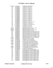
...89 IC,LINEAR(SMD) RT9161-25CX RICHTEKSOT-89 IC,LINEAR 24LC I6B MICROCHI IC,DIGITAL MTV212MX64X(MTP) MYSON BEAD,HI-IMPEDANCE 3216MZ 200.000HM I VE150(b)-2 Service Manual LOCATION C138 C139 C140 C141 C142 C143 C144 C145 C146 C147 C148 C149 C150 C151 C152 C153 C154 C161 C166 C167 C169 C170 C171 C172... I004(RA) I004(RB) I005 I006 I007(RA) I007(RB) I008 I009 L001 L002 L003 L004 L005 L007 L008 L009 LO10 L011 L012 L013 L014 ViewSonic P/N E-C-0404-3815 E-C-0404-3900 E-C-0404-3900 E-C-0404-3900 E-C-0404-3900 E-C-0404-3900 E-C-0404-3900 E-C-0404-3900 E-C-0404-3900 E-C-0404-3900 E-C-0404-3900 E-C-0404-...
...89 IC,LINEAR(SMD) RT9161-25CX RICHTEKSOT-89 IC,LINEAR 24LC I6B MICROCHI IC,DIGITAL MTV212MX64X(MTP) MYSON BEAD,HI-IMPEDANCE 3216MZ 200.000HM I VE150(b)-2 Service Manual LOCATION C138 C139 C140 C141 C142 C143 C144 C145 C146 C147 C148 C149 C150 C151 C152 C153 C154 C161 C166 C167 C169 C170 C171 C172... I004(RA) I004(RB) I005 I006 I007(RA) I007(RB) I008 I009 L001 L002 L003 L004 L005 L007 L008 L009 LO10 L011 L012 L013 L014 ViewSonic P/N E-C-0404-3815 E-C-0404-3900 E-C-0404-3900 E-C-0404-3900 E-C-0404-3900 E-C-0404-3900 E-C-0404-3900 E-C-0404-3900 E-C-0404-3900 E-C-0404-3900 E-C-0404-3900 E-C-0404-...
Service Manual
Page 32
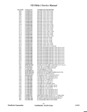
...J P=0.8 RES,CHIP NETWORKS 08P*04R I /10W 100.00 .1 TI608 RES,CHIP 1/10W 4.70K J T1608 RES,CHIP 1/10W 2.70K J T1608 RES,CHIP 1/10W 1 0.00K J. VE150(b)-2 Service Manual LOCATION R094 R095 R096 R097 R100 R101 R102 R106 R107 R108 R111 R112 R115 R116 R117 R118 R119 R120 R121 R122 R123 R124 R125 R126... U001 X001 X002 D701 P701 S701 S705 U701 C826 C827 C829 C830 C831 C832 C833 C834 C836 C837 C838 C839 C849 D811 D8I2 I804 I805 ViewSonic P/N E-R-0405-6419 E-R-0405-6419 E-R-0405-6419 E-R-0405-6419 E-R-0405-6419 E-R-0405-6419 E-R-0405-6419 E-R-0405-6603 E-R-0405-6603 E-R-0405-6601 E-R-0405-6409 E-R-...
...J P=0.8 RES,CHIP NETWORKS 08P*04R I /10W 100.00 .1 TI608 RES,CHIP 1/10W 4.70K J T1608 RES,CHIP 1/10W 2.70K J T1608 RES,CHIP 1/10W 1 0.00K J. VE150(b)-2 Service Manual LOCATION R094 R095 R096 R097 R100 R101 R102 R106 R107 R108 R111 R112 R115 R116 R117 R118 R119 R120 R121 R122 R123 R124 R125 R126... U001 X001 X002 D701 P701 S701 S705 U701 C826 C827 C829 C830 C831 C832 C833 C834 C836 C837 C838 C839 C849 D811 D8I2 I804 I805 ViewSonic P/N E-R-0405-6419 E-R-0405-6419 E-R-0405-6419 E-R-0405-6419 E-R-0405-6419 E-R-0405-6419 E-R-0405-6419 E-R-0405-6603 E-R-0405-6603 E-R-0405-6601 E-R-0405-6409 E-R-...
Service Manual
Page 33
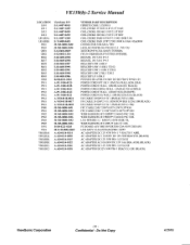
VE150(b)-2 Service Manual LOCATION L8I0 L811 L812 L813 L814(RA) L814(RB) P801 P803 Q801 Q802 R836 R837 R839 R841 R842 R843 R845 U802 P951 P951 P951 P952 P952 P961 P961 P961 P980 P981 P982 P983 P984 P985 U901 V901 Y801(RA) Y801(RA) Y801(RB) Y801(RB) Y801(RC) Y801(RC) ViewSonic...-0808-5495 M-MS-0808-5496 M-MS-0808-5493 M-MS-0808-5494 B-SB-0221-0203 M-LCD-0826-0069 A-AD-0114-0114 A-AD-0114-0095 A-AD-0114-0115 A-AD-0114-0122 A-...0114-0116 A-AD-0114-0118 VENDOR PART DESCRIPTION FERRITE CORE 3.5X9X0.8 COIL,CHOKE JTI56E1 0.8*15.5T 10uH COIL,CHOKE JD156G 15UF 21.5T REF COIL,CHOKE JD156G ISUF 21.5T REF...
VE150(b)-2 Service Manual LOCATION L8I0 L811 L812 L813 L814(RA) L814(RB) P801 P803 Q801 Q802 R836 R837 R839 R841 R842 R843 R845 U802 P951 P951 P951 P952 P952 P961 P961 P961 P980 P981 P982 P983 P984 P985 U901 V901 Y801(RA) Y801(RA) Y801(RB) Y801(RB) Y801(RC) Y801(RC) ViewSonic...-0808-5495 M-MS-0808-5496 M-MS-0808-5493 M-MS-0808-5494 B-SB-0221-0203 M-LCD-0826-0069 A-AD-0114-0114 A-AD-0114-0095 A-AD-0114-0115 A-AD-0114-0122 A-...0114-0116 A-AD-0114-0118 VENDOR PART DESCRIPTION FERRITE CORE 3.5X9X0.8 COIL,CHOKE JTI56E1 0.8*15.5T 10uH COIL,CHOKE JD156G 15UF 21.5T REF COIL,CHOKE JD156G ISUF 21.5T REF...


