User Guide
Page 2
... Control Components 4 Remote Control Components Diagram 4 Inserting the Batteries 5 Installation 6 Angle Adjustment 6 Cabling ...7 Power Connection 7 Example of System Setup 8 Plug & Play ...8 Operations 9 Power ON ...9 Power OFF ...9 Basic Operation 10 MAIN Menu ...12 PICTURE-1 Menu 13 PICTURE-2 Menu 14 INPUT Menu ...15 SCREEN Menu 16 OPTION Menu 17 Maintenance 18 Lamp ...18 Lamp Life ...18 Replacing the Lamp 19 Resetting the Lamp Timer 19 Air-Filter ...20 Maintenance Inside the Equipment 20 Cleaning the Lens 20 Cleaning the Cabinet and Remote Control 20 ViewSonic PJ500...
... Control Components 4 Remote Control Components Diagram 4 Inserting the Batteries 5 Installation 6 Angle Adjustment 6 Cabling ...7 Power Connection 7 Example of System Setup 8 Plug & Play ...8 Operations 9 Power ON ...9 Power OFF ...9 Basic Operation 10 MAIN Menu ...12 PICTURE-1 Menu 13 PICTURE-2 Menu 14 INPUT Menu ...15 SCREEN Menu 16 OPTION Menu 17 Maintenance 18 Lamp ...18 Lamp Life ...18 Replacing the Lamp 19 Resetting the Lamp Timer 19 Air-Filter ...20 Maintenance Inside the Equipment 20 Cleaning the Lens 20 Cleaning the Cabinet and Remote Control 20 ViewSonic PJ500...
User Guide
Page 6
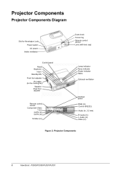
... Components Diagram Slot for Kensington Lock Power switch AC power Intake ventilation Control panel Reset Keystone Input Standby/ON Front foot adjuster Air intake (for the cooling fan) Speaker Rear foot adjuster Remote control sensor Component Video Y (In) CB/PB (In) CR/PR (In) S-Video (In) Zoom knob Focus ring Remote control sensor Lens (with lens cap) Lamp indicator Temp indicator Power indicator Menu Exhaust ventilation Interface panel RGB (In) Control (RS232) Audio (In, 3.5 mm) R Audio (In) L Audio (In) Video (In) Figure 2: Projector Components 3 ViewSonic PJ500/PJ550/PJ501/PJ551
... Components Diagram Slot for Kensington Lock Power switch AC power Intake ventilation Control panel Reset Keystone Input Standby/ON Front foot adjuster Air intake (for the cooling fan) Speaker Rear foot adjuster Remote control sensor Component Video Y (In) CB/PB (In) CR/PR (In) S-Video (In) Zoom knob Focus ring Remote control sensor Lens (with lens cap) Lamp indicator Temp indicator Power indicator Menu Exhaust ventilation Interface panel RGB (In) Control (RS232) Audio (In, 3.5 mm) R Audio (In) L Audio (In) Video (In) Figure 2: Projector Components 3 ViewSonic PJ500/PJ550/PJ501/PJ551

User Guide
Page 9
.... Installation Refer to the graphics and table on critical parts (i.e. Screen a Distance from the lens center to the bottom of the projector to 9°. ViewSonic PJ500/PJ550/PJ501/PJ551 6 LCD panel, lens assembly, etc.) Angle Adjustment Use the foot adjusters on the bottom of the screen (+10%). other positions can cause heat build-up the front side of the displayed image. Foot Adjuster Press the foot adjuster button Rear Foot Adjuster...
.... Installation Refer to the graphics and table on critical parts (i.e. Screen a Distance from the lens center to the bottom of the projector to 9°. ViewSonic PJ500/PJ550/PJ501/PJ551 6 LCD panel, lens assembly, etc.) Angle Adjustment Use the foot adjusters on the bottom of the screen (+10%). other positions can cause heat build-up the front side of the displayed image. Foot Adjuster Press the foot adjuster button Rear Foot Adjuster...

User Guide
Page 10
... video input S-video input Video input/ Audio input Audio Input RGB Table 2: Cabling Terminal CONTROL VIDEO Y VIDEO CB/PB VIDEO CR/PR S-VIDEO VIDEO AUDIO (L) AUDIO (R) 3.5 mm to mini-jack L/R Cable Accessory RGB cable or optional RGB cable with D-sub 15-pin shrink jack and inch thread screws Optional RS-232C cable Accessory component video cable Accessory S-video cable with mini DIN 4-pin jack Accessory video/audio cable with this projector. Power Connection Use the correct power cord supplied with the product. NOTE: • Before connecting, read the instruction manuals...
... video input S-video input Video input/ Audio input Audio Input RGB Table 2: Cabling Terminal CONTROL VIDEO Y VIDEO CB/PB VIDEO CR/PR S-VIDEO VIDEO AUDIO (L) AUDIO (R) 3.5 mm to mini-jack L/R Cable Accessory RGB cable or optional RGB cable with D-sub 15-pin shrink jack and inch thread screws Optional RS-232C cable Accessory component video cable Accessory S-video cable with mini DIN 4-pin jack Accessory video/audio cable with this projector. Power Connection Use the correct power cord supplied with the product. NOTE: • Before connecting, read the instruction manuals...
User Guide
Page 11
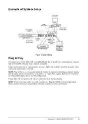
... INF display driver files for more information. ViewSonic PJ500/PJ550/PJ501/PJ551 8 Please use this function by connecting to RGB (In) of Video/Audio cable S-Video Player Notebook Computer Plug & Play Figure 8: System Setup This projector is VESA DDC (Display Data Channel) compatible. Refer to an Apple computer. This projector is a system configured with a notebook computer, set the proper RGB external image output. Please read the instruction manual of...
... INF display driver files for more information. ViewSonic PJ500/PJ550/PJ501/PJ551 8 Please use this function by connecting to RGB (In) of Video/Audio cable S-Video Player Notebook Computer Plug & Play Figure 8: System Setup This projector is VESA DDC (Display Data Channel) compatible. Refer to an Apple computer. This projector is a system configured with a notebook computer, set the proper RGB external image output. Please read the instruction manual of...
User Guide
Page 12
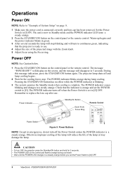
... control pad flashes orange during lamp cooling. Check that the projector is connected correctly and lens cap has been removed. will display on page 8. 1 Make sure the power cord is ready to [O]. Power Indicator Standby/On Button Zoom Knob Focus Ring Remote Control Power Switch Figure 9: Power Buttons NOTE: Except in green. 3 After several seconds the lamp will stop . Otherwise improper cooling of System Setup" on the screen, and the message will reduce the life of the projected image with the Zoom knob. 5 Adjust focus using...
... control pad flashes orange during lamp cooling. Check that the projector is connected correctly and lens cap has been removed. will display on page 8. 1 Make sure the power cord is ready to [O]. Power Indicator Standby/On Button Zoom Knob Focus Ring Remote Control Power Switch Figure 9: Power Buttons NOTE: Except in green. 3 After several seconds the lamp will stop . Otherwise improper cooling of System Setup" on the screen, and the message will reduce the life of the projected image with the Zoom knob. 5 Adjust focus using...
User Guide
Page 13
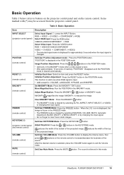
...top Set/Clear VOLUME Mode: Press the VOLUME button to display the Volume menu, then press / sound. Set/Clear Mute Mode: Press the MUTE button. RGB J VIDEO J S-VIDEO J COMPONENT (JRGB) Select RGB Input: Press the RGB button. reduces the width of the projected image. buttons on the remote control. MAGNIFY (-) reduces the image. Adjust Keystone: Press the / buttons in the MAGNIFY mode. Initialize Position Adjustment: Press the RESET button in MAGNIFY mode. FREEZE (remote control) KEYSTONE (*) (projector control panel and remote control) VOLUME (remote control...
...top Set/Clear VOLUME Mode: Press the VOLUME button to display the Volume menu, then press / sound. Set/Clear Mute Mode: Press the MUTE button. RGB J VIDEO J S-VIDEO J COMPONENT (JRGB) Select RGB Input: Press the RGB button. reduces the width of the projected image. buttons on the remote control. MAGNIFY (-) reduces the image. Adjust Keystone: Press the / buttons in the MAGNIFY mode. Initialize Position Adjustment: Press the RESET button in MAGNIFY mode. FREEZE (remote control) KEYSTONE (*) (projector control panel and remote control) VOLUME (remote control...
User Guide
Page 14
... screen color for other signal inputs with some input signals. Set/ Clear Blank Mode: press the BLANK button. To return to proceed. Horizontal Position (H. SIZE), are automatically adjusted. • Before using the AUTO feature, be the selected input when the projector is powered back on the remote control to the initial signal input. A blank screen (no signal is detected, it turns back to search for blank mode. Select Menu: Press the / buttons to select the menu (MAIN, PICTURE-1, PICTURE-2, INPUT, SCREEN...
... screen color for other signal inputs with some input signals. Set/ Clear Blank Mode: press the BLANK button. To return to proceed. Horizontal Position (H. SIZE), are automatically adjusted. • Before using the AUTO feature, be the selected input when the projector is powered back on the remote control to the initial signal input. A blank screen (no signal is detected, it turns back to search for blank mode. Select Menu: Press the / buttons to select the menu (MAIN, PICTURE-1, PICTURE-2, INPUT, SCREEN...

User Guide
Page 16
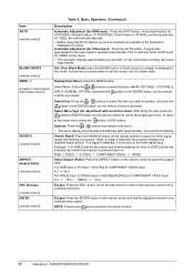
... COLOR BAL R COLOR BAL B SHARPNESS COLOR TINT Table 5: PICTURE-1Menu Actions/Description Adjust Red Color Balance: Darker Lighter Adjust Blue Color Balance: Darker Lighter Adjust Sharpness (for VIDEO/S-VIDEO): Sharper Softer Adjust COLOR (for VIDEO/S-VIDEO/COMPONENT VIDEO): Darker Adjust Tint (for VIDEO/S-VIDEO): More Green More Red Lighter 13 ViewSonic PJ500/PJ550/PJ501/PJ551 Item LANGUAGE Table 4: MAIN Menu (Continued) Actions/Description Select Menu Language: Press the / button to adjust with the / buttons and press the button or the ENTER button...
... COLOR BAL R COLOR BAL B SHARPNESS COLOR TINT Table 5: PICTURE-1Menu Actions/Description Adjust Red Color Balance: Darker Lighter Adjust Blue Color Balance: Darker Lighter Adjust Sharpness (for VIDEO/S-VIDEO): Sharper Softer Adjust COLOR (for VIDEO/S-VIDEO/COMPONENT VIDEO): Darker Adjust Tint (for VIDEO/S-VIDEO): More Green More Red Lighter 13 ViewSonic PJ500/PJ550/PJ501/PJ551 Item LANGUAGE Table 4: MAIN Menu (Continued) Actions/Description Select Menu Language: Press the / button to adjust with the / buttons and press the button or the ENTER button...

User Guide
Page 18
... function when the image becomes unstable at the same time. Item AUTO VIDEO HDTV SYNC ON G Table 7: INPUT Menu Actions/Description Auto Adjust (for the current input signal. Use this function is inactive. The SYNC ON G mode enables the SYNC on . Select the item you want to the description of the item VIDEO below. • This function may not function correctly with the input signal, the picture may be...
... function when the image becomes unstable at the same time. Item AUTO VIDEO HDTV SYNC ON G Table 7: INPUT Menu Actions/Description Auto Adjust (for the current input signal. Use this function is inactive. The SYNC ON G mode enables the SYNC on . Select the item you want to the description of the item VIDEO below. • This function may not function correctly with the input signal, the picture may be...

User Guide
Page 19
... / button to the following table. Please select the item you can operate according to select one of these options: • Blue blank screen • White blank screen • Black blank screen The Blank Screen is detected. The plain screen of the Table 3: Basic Operation. On/Off START UP Screen: TURN ON TURN OFF The START UP screen is fixed screen displays when no signal is for the BLANK mode. SCREEN Menu The SCREEN menu has...
... / button to the following table. Please select the item you can operate according to select one of these options: • Blue blank screen • White blank screen • Black blank screen The Blank Screen is detected. The plain screen of the Table 3: Basic Operation. On/Off START UP Screen: TURN ON TURN OFF The START UP screen is fixed screen displays when no signal is for the BLANK mode. SCREEN Menu The SCREEN menu has...
User Guide
Page 20
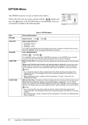
... "Air-Filter" and "Replacing the Filter" on screen is selected. Select WHISPER Mode: NORMAL WHISPER The WHISPER mode is active when WHISPER is lowered. Reset Filter Time [Use this item displays the time that the projector lamp has been used . Please select the item you can operate according to Lamp Time: The starting of this function only when the filter is replaced!] : Keep pressing the RESET button for the set time. Refer to the following table. OPTION Menu...
... "Air-Filter" and "Replacing the Filter" on screen is selected. Select WHISPER Mode: NORMAL WHISPER The WHISPER mode is active when WHISPER is lowered. Reset Filter Time [Use this item displays the time that the projector lamp has been used . Please select the item you can operate according to Lamp Time: The starting of this function only when the filter is replaced!] : Keep pressing the RESET button for the set time. Refer to the following table. OPTION Menu...

User Guide
Page 21
... high temperatures. HIGH VOLTAGE HIGH TEMPERATURE HIGH PRESSURE WARNINGS • Dispose of the used for part numbers. NOTE: The LAMP indicator is still red replace the lamp. The lamp is protected by broken or shattered glass. Before replacing the lamp switch the POWER OFF, wait approximately 20 minutes, and switch the POWER ON again. ViewSonic PJ500/PJ550/PJ501/PJ551 18 The image will become darker and hues will become weaker after a lamp has been used lamp according to replace...
... high temperatures. HIGH VOLTAGE HIGH TEMPERATURE HIGH PRESSURE WARNINGS • Dispose of the used for part numbers. NOTE: The LAMP indicator is still red replace the lamp. The lamp is protected by broken or shattered glass. Before replacing the lamp switch the POWER OFF, wait approximately 20 minutes, and switch the POWER ON again. ViewSonic PJ500/PJ550/PJ501/PJ551 18 The image will become darker and hues will become weaker after a lamp has been used lamp according to replace...

User Guide
Page 22
... ViewSonic PJ500/PJ550/PJ501/PJ551 If you see this message you may result in uneven coloring. 6 Install the new lamp and tighten the one screw, and gently remove the lamp while holding the grips. Replacing the Lamp When the indicator shows that there is zero (0) hours of lamp life remaining, the unit will automatically shut off automatically after 10 minutes. 1 Switch POWER ON. 2 From the OPTION menu select LAMP TIME with the lamp cover removed. Screws...
... ViewSonic PJ500/PJ550/PJ501/PJ551 If you see this message you may result in uneven coloring. 6 Install the new lamp and tighten the one screw, and gently remove the lamp while holding the grips. Replacing the Lamp When the indicator shows that there is zero (0) hours of lamp life remaining, the unit will automatically shut off automatically after 10 minutes. 1 Switch POWER ON. 2 From the OPTION menu select LAMP TIME with the lamp cover removed. Screws...
User Guide
Page 23
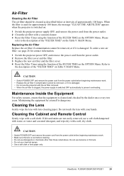
.... 1 Switch the projector power OFF, and remove the power cord from the power outlet before beginning maintenance work. • Make sure the lens is cool before beginning maintenance work. • Replace the air filter if contamination cannot be cleaned as described below at intervals of approximately 100 hours. Cleaning the Cabinet and Remote Control Gently wipe with a vacuum cleaner. 3 Reset the Filter Timer using the function of the FILTER TIME on the OPTION Menu. ViewSonic PJ500/PJ550...
.... 1 Switch the projector power OFF, and remove the power cord from the power outlet before beginning maintenance work. • Make sure the lens is cool before beginning maintenance work. • Replace the air filter if contamination cannot be cleaned as described below at intervals of approximately 100 hours. Cleaning the Cabinet and Remote Control Gently wipe with a vacuum cleaner. 3 Reset the Filter Timer using the function of the FILTER TIME on the OPTION Menu. ViewSonic PJ500/PJ550...

User Guide
Page 24
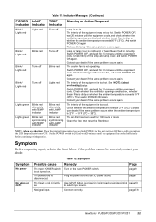
... openings blocked? • Is the air filter dirty? • Is the ambient temperature in a few minutes. The Standby mode has been set. Normal operation possible. Please wait. Please wait. The error is switched off automatically when the lamp reaches the end of its life. Take the appropriate measures when such messages appear. prepare a new lamp for installation. Always reset the lamp timer after replacing the lamp. Check the specifications of its life in ** hours. POWER LAMP indicator indicator Lights orange Turns off Blinks green Turns...
... openings blocked? • Is the air filter dirty? • Is the ambient temperature in a few minutes. The Standby mode has been set. Normal operation possible. Please wait. Please wait. The error is switched off automatically when the lamp reaches the end of its life. Take the appropriate measures when such messages appear. prepare a new lamp for installation. Always reset the lamp timer after replacing the lamp. Check the specifications of its life in ** hours. POWER LAMP indicator indicator Lights orange Turns off Blinks green Turns...
User Guide
Page 25
... hours or more. The air-filter has been used for 20 minutes until the equipment cools. Table 11: Indicator Messages (Continued) POWER LAMP TEMP Meaning or Action Required indicator indicator indicator Blinks/ Lights red Blinks/ Lights red Blinks/ Lights red Blinks/ Lights red Lights green Lights green Lights red Turns off Blinks red Turns off Turns off Blinks red Turns off Lights red Blinks red alternately with TEMP indicator Blinks red alternately with LAMP indicator Blinks red synchronizing with TEMP indicator Blinks red synchronizing with operation. Switch POWER...
... hours or more. The air-filter has been used for 20 minutes until the equipment cools. Table 11: Indicator Messages (Continued) POWER LAMP TEMP Meaning or Action Required indicator indicator indicator Blinks/ Lights red Blinks/ Lights red Blinks/ Lights red Blinks/ Lights red Lights green Lights green Lights red Turns off Blinks red Turns off Turns off Blinks red Turns off Lights red Blinks red alternately with TEMP indicator Blinks red alternately with LAMP indicator Blinks red synchronizing with TEMP indicator Blinks red synchronizing with operation. Switch POWER...
User Guide
Page 26
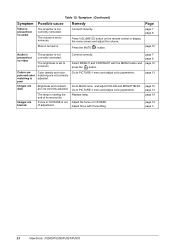
... VOLUME button on . Focus or H PHASE is out of its service life. Go to PICTURE-1 menu and adjust color parameters. Go to PICTURE-1 menu and adjust color parameters. Mute is turned on the remote control or display the menu screen and adjust the volume. Page page 7 page 8 page 10 Audio is present but no video The projector is not correctly connected. Brightness and contrast are blurred The lamp is nearing the end of adjustment. Adjust the focus...
... VOLUME button on . Focus or H PHASE is out of its service life. Go to PICTURE-1 menu and adjust color parameters. Go to PICTURE-1 menu and adjust color parameters. Mute is turned on the remote control or display the menu screen and adjust the volume. Page page 7 page 8 page 10 Audio is present but no video The projector is not correctly connected. Brightness and contrast are blurred The lamp is nearing the end of adjustment. Adjust the focus...

User Guide
Page 30
... electric power fluctuations or failure. Who the warranty protects: This warranty is effective: ViewSonic projectors are warranted separately. What the warranty does not cover: 1. e. g. Normal wear and tear. How to an authorized ViewSonic service center or ViewSonic. 4. You will at its products to provide (a) the original dated sales slip, (b) your name, (c) your address, (d) a description of the problem, and (e) the serial number of...
... electric power fluctuations or failure. Who the warranty protects: This warranty is effective: ViewSonic projectors are warranted separately. What the warranty does not cover: 1. e. g. Normal wear and tear. How to an authorized ViewSonic service center or ViewSonic. 4. You will at its products to provide (a) the original dated sales slip, (b) your name, (c) your address, (d) a description of the problem, and (e) the serial number of...

User Guide
Page 32
.... Compliance Information for Canada Notice: This class B digital apparatus complies with the projector or specified. These limits are included with Canadian ICES-003. This equipment generates, uses, and can radiate radio frequency energy, and if not installed and used , use grounded power supply cord and the provided shielded video interface cable with the instructions, may cause harmful interference to which can be...
.... Compliance Information for Canada Notice: This class B digital apparatus complies with the projector or specified. These limits are included with Canadian ICES-003. This equipment generates, uses, and can radiate radio frequency energy, and if not installed and used , use grounded power supply cord and the provided shielded video interface cable with the instructions, may cause harmful interference to which can be...


