User Guide
Page 2
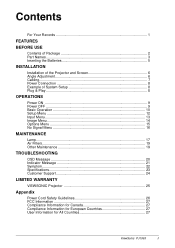
... USE Contents of Package 2 Part Names...3 Inserting the Batteries 5 INSTALLATION Installation of the Projector and Screen 6 Angle Adjustment 6 Cabling...7 Power Connection 8 Example of System Setup 8 Plug & Play ...8 OPERATIONS Power ON ...9 Power OFF ...9 Basic Operation 10 Setup Menu ...12 Input Menu...13 Image Menu...14 Options Menu 15 No Signal Menu 16 MAINTENANCE Lamp...17 Air Filters...19 Other Maintenance 19 TROUBLESHOOTING OSD Message 20 Indicator Message 21 Symptom...22 Specifications 23 Customer Support 24 LIMITED WARRANTY VIEWSONIC Projector 25 Appendix Power Cord...
... USE Contents of Package 2 Part Names...3 Inserting the Batteries 5 INSTALLATION Installation of the Projector and Screen 6 Angle Adjustment 6 Cabling...7 Power Connection 8 Example of System Setup 8 Plug & Play ...8 OPERATIONS Power ON ...9 Power OFF ...9 Basic Operation 10 Setup Menu ...12 Input Menu...13 Image Menu...14 Options Menu 15 No Signal Menu 16 MAINTENANCE Lamp...17 Air Filters...19 Other Maintenance 19 TROUBLESHOOTING OSD Message 20 Indicator Message 21 Symptom...22 Specifications 23 Customer Support 24 LIMITED WARRANTY VIEWSONIC Projector 25 Appendix Power Cord...

User Guide
Page 3
VGA, and XGA are registered trademarks of charge at : http://www.viewsonic.com Image Optimization files are registered trademarks of ViewSonic Corporation. ENERGY STAR® is concerned about proper disposal. Electronic Warranty Registration To meet your future needs, and to change without notice. For Your Records Product Name: Model Number: Document Number Serial Number: Purchase Date: ViewSonic PJ1065 VPROJ24268-2W A-CD-PJ1065-2 Product disposal at...
VGA, and XGA are registered trademarks of charge at : http://www.viewsonic.com Image Optimization files are registered trademarks of ViewSonic Corporation. ENERGY STAR® is concerned about proper disposal. Electronic Warranty Registration To meet your future needs, and to change without notice. For Your Records Product Name: Model Number: Document Number Serial Number: Purchase Date: ViewSonic PJ1065 VPROJ24268-2W A-CD-PJ1065-2 Product disposal at...
User Guide
Page 5
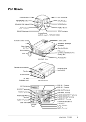
...Names ZOOM Button KEYSTONE Button STANDBY/ON Button LAMP Indicator POWER Indicator Remote control sensor Lens Filter Cover (air filter) Foot adjuster Lens cap FOCUS Button INPUT Button MENU Button RESET Button TEMP Indicator Control Panel (refer to page 9, "OPERATIONS") Front/right view Control panel Ventilation openings (exhaust) Carrying Handle Filter cover (air filter and intake for the cooling fan) Foot adjuster Remote control sensor Speaker Power switch AC inlet (to power cord) Rear/Left view DVI Terminal S-VIDEO Terminal VIDEO Terminal AUDIO (MONO)/L Terminal AUDIO R Terminal USB...
...Names ZOOM Button KEYSTONE Button STANDBY/ON Button LAMP Indicator POWER Indicator Remote control sensor Lens Filter Cover (air filter) Foot adjuster Lens cap FOCUS Button INPUT Button MENU Button RESET Button TEMP Indicator Control Panel (refer to page 9, "OPERATIONS") Front/right view Control panel Ventilation openings (exhaust) Carrying Handle Filter cover (air filter and intake for the cooling fan) Foot adjuster Remote control sensor Speaker Power switch AC inlet (to power cord) Rear/Left view DVI Terminal S-VIDEO Terminal VIDEO Terminal AUDIO (MONO)/L Terminal AUDIO R Terminal USB...
User Guide
Page 8
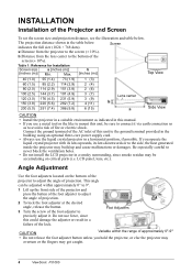
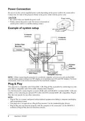
...-core power supply cord. • Always use force, since this unit to precisely adjust it via earth connection so as indicated in a horizontal position, if possible. The projection distance shown in a failure of the lock. Max. Connect the ground terminal of the AC inlet of this could damage the adjuster or result in the table below . LCD panel, lens, etc.). Screen a:Distance from the lens center to the screen (±...
...-core power supply cord. • Always use force, since this unit to precisely adjust it via earth connection so as indicated in a horizontal position, if possible. The projection distance shown in a failure of the lock. Max. Connect the ground terminal of the AC inlet of this could damage the adjuster or result in the table below . LCD panel, lens, etc.). Screen a:Distance from the lens center to the screen (±...
User Guide
Page 9
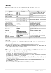
... the RS-232C communication data, refer to the service manual of PJ1065-2. • If you connect the projector, be sure to read the manual of the projector to each device. Function Analog RGB input Analog RGB output Digital RGB input Audio input (from the computer) PS/2 mouse control ADB mouse control Serial mouse control RS/232C communication USB mouse control S-video input Video input Component video input Audio input (from video equipment) Audio output Table 2: Cabling Terminal Cable RGB IN 1 RGB...
... the RS-232C communication data, refer to the service manual of PJ1065-2. • If you connect the projector, be sure to read the manual of the projector to each device. Function Analog RGB input Analog RGB output Digital RGB input Audio input (from the computer) PS/2 mouse control ADB mouse control Serial mouse control RS/232C communication USB mouse control S-video input Video input Component video input Audio input (from video equipment) Audio output Table 2: Cabling Terminal Cable RGB IN 1 RGB...
User Guide
Page 10
... to be connected. Use this function by connecting the accessory RGB cable with the power cord. Use the RGB IN 2 terminal if Plug & Play does not function correctly. 8 ViewSonic PJ1065 NOTE: • Plug & Play is a system configured with peripheral equipment including a computer and display, and an operating system. • This projector is recognized as to activate the RGB external image output (setting it to...
... to be connected. Use this function by connecting the accessory RGB cable with the power cord. Use the RGB IN 2 terminal if Plug & Play does not function correctly. 8 ViewSonic PJ1065 NOTE: • Plug & Play is a system configured with peripheral equipment including a computer and display, and an operating system. • This projector is recognized as to activate the RGB external image output (setting it to...
User Guide
Page 11
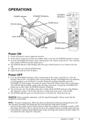
...ON Button FOCUS button ZOOM button Power Switch FOCUS button Lens cap ZOOM button Power ON 1 Check if the power cord is used safely. Remove the lens cap. 5 Adjust picture size with the ZOOM button. 6 Adjust focus with the FOCUS button. Pressing the STANDBY/ON button has no operation is blinking. 2 The system goes into the Standby mode after -image. Always ensure that the equipment is connected correctly. 2 Set the power switch to [0]. 3 The POWER indicator goes out when the power is turned off . Do not project the same image for turning the power off ?" ViewSonic PJ1065 9 When...
...ON Button FOCUS button ZOOM button Power Switch FOCUS button Lens cap ZOOM button Power ON 1 Check if the power cord is used safely. Remove the lens cap. 5 Adjust picture size with the ZOOM button. 6 Adjust focus with the FOCUS button. Pressing the STANDBY/ON button has no operation is blinking. 2 The system goes into the Standby mode after -image. Always ensure that the equipment is connected correctly. 2 Set the power switch to [0]. 3 The POWER indicator goes out when the power is turned off . Do not project the same image for turning the power off ?" ViewSonic PJ1065 9 When...

User Guide
Page 12
... the operation of the remote control device. 10 ViewSonic PJ1065 Item INPUT SELECT POSITION RESET (*) MAGNIFY FREEZE Table 3: Basic Operation Description Select Input Signal (*): Press the INPUT button. Set/Clear Position Adjustment Mode: Press the POSITION button. Items indicated by way of the projector's control panel. RGB IN 1/RGB IN 2/DVI→VIDEO/S-VIDEO/COMPONENT VIDEO VIDEO→S-VIDEO→COMPONENT VIDEO (→VIDEO) • The selected signal name is extinguished and the POSITION mode will interfere with the supplied remote control...
... the operation of the remote control device. 10 ViewSonic PJ1065 Item INPUT SELECT POSITION RESET (*) MAGNIFY FREEZE Table 3: Basic Operation Description Select Input Signal (*): Press the INPUT button. Set/Clear Position Adjustment Mode: Press the POSITION button. Items indicated by way of the projector's control panel. RGB IN 1/RGB IN 2/DVI→VIDEO/S-VIDEO/COMPONENT VIDEO VIDEO→S-VIDEO→COMPONENT VIDEO (→VIDEO) • The selected signal name is extinguished and the POSITION mode will interfere with the supplied remote control...

User Guide
Page 13
... (H. Use with the control panel. It may operate as the mouse control button. No image is heard in the Blank mode. Refer to select the normal menu or the single menu. MODE ZOOM (*) FOCUS (*) KEYSTONE (*) Select Mode of inactivity. Display: Press the PinP button. Item VOLUME MUTE AUTO BLANK ON/ OFF MENU ON/ OFF (*) MENU SELECT Table 3: Basic Operation (continued) Description Volume Adjustment: Press the VOLUME button. Set/Clear Mute Mode: Press the MUTE button. SIZE) are displayed...
... (H. Use with the control panel. It may operate as the mouse control button. No image is heard in the Blank mode. Refer to select the normal menu or the single menu. MODE ZOOM (*) FOCUS (*) KEYSTONE (*) Select Mode of inactivity. Display: Press the PinP button. Item VOLUME MUTE AUTO BLANK ON/ OFF MENU ON/ OFF (*) MENU SELECT Table 3: Basic Operation (continued) Description Volume Adjustment: Press the VOLUME button. Set/Clear Mute Mode: Press the MUTE button. SIZE) are displayed...

User Guide
Page 15
... sync signal frequencies for RGB input. • Valid only at maximum size in this problem. • This function is the same as appropriate for the input signal with the button. The selection of the screen for the N-PAL input. • Use this function to raise resolution, at RGB Input: Select the EXECUTE with some input signals. the image becomes irregular, or lacks color) at Video Input), except for the video input...
... sync signal frequencies for RGB input. • Valid only at maximum size in this problem. • This function is the same as appropriate for the input signal with the button. The selection of the screen for the N-PAL input. • Use this function to raise resolution, at RGB Input: Select the EXECUTE with some input signals. the image becomes irregular, or lacks color) at Video Input), except for the video input...

User Guide
Page 16
... blue screen at RGB IN 1, RGB IN 2 or DVI input. Select Position of the MyScreen menu. INPUT GAMMA Table 6: Image Menu Description Select Blank Screen: Select the screen with the NORMAL CINEMA DYNAMIC button. 14 ViewSonic PJ1065 Mode of MyScreen below . IN P. mode and start or stop operation with the and buttons, and start capturing. It requires about 10 seconds. Refer to the MyScreen Capture Position mode, press the RESET button. VIDEO S-VIDEO...
... blue screen at RGB IN 1, RGB IN 2 or DVI input. Select Position of the MyScreen menu. INPUT GAMMA Table 6: Image Menu Description Select Blank Screen: Select the screen with the NORMAL CINEMA DYNAMIC button. 14 ViewSonic PJ1065 Mode of MyScreen below . IN P. mode and start or stop operation with the and buttons, and start capturing. It requires about 10 seconds. Refer to the MyScreen Capture Position mode, press the RESET button. VIDEO S-VIDEO...

User Guide
Page 18
... signal is input MyScreen is a mode that the customer-customized screen is received, set time. MyScreen is a mode that the factory fixed screen is displayed. • When MyScreen or ORIGINAL is selected, the screen is valid. Refer to the description of MyScreen below . AUTO OFF Operation start/stop: Press the button. Item Table 8: No Signal Menu Description VOLUME Volume Adjustment: Reduce VOLUME Increase VOLUME • When this function is used, audio input...
... signal is input MyScreen is a mode that the customer-customized screen is received, set time. MyScreen is a mode that the factory fixed screen is displayed. • When MyScreen or ORIGINAL is selected, the screen is valid. Refer to the description of MyScreen below . AUTO OFF Operation start/stop: Press the button. Item Table 8: No Signal Menu Description VOLUME Volume Adjustment: Reduce VOLUME Increase VOLUME • When this function is used, audio input...
User Guide
Page 19
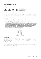
... that the lamp has exploded (explosive sound is still red, replace the lamp. The lamp is made of time. Replace the lamp if the LAMP indicator is red, or the CHANGE THE LAMP message appears when the projector is also red when the lamp unit reaches high temperature. NOTE: • The LAMP indicator is switched ON. WARNING: • For disposal of used for a long period of glass, do not apply shock to replace lamp. The image will become...
... that the lamp has exploded (explosive sound is still red, replace the lamp. The lamp is made of time. Replace the lamp if the LAMP indicator is red, or the CHANGE THE LAMP message appears when the projector is also red when the lamp unit reaches high temperature. NOTE: • The LAMP indicator is switched ON. WARNING: • For disposal of used for a long period of glass, do not apply shock to replace lamp. The image will become...
User Guide
Page 20
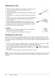
... ViewSonic PJ1065 The power will appear on the lamp timer on the bottom of the screen. 2 Press the MENU button on the remote control transmitter, or the RESET button on the control panel, while the lamp timer is displayed, complete the following operation within ten minutes of the screwed lamp into the unit. 7 Replace the lamp cover in the diagram, and remove the lamp cover. 5 Loosen the two screws, and gently remove the lamp while holding the grips. Replacing the Lamp 1 Switch...
... ViewSonic PJ1065 The power will appear on the lamp timer on the bottom of the screen. 2 Press the MENU button on the remote control transmitter, or the RESET button on the control panel, while the lamp timer is displayed, complete the following operation within ten minutes of the screwed lamp into the unit. 7 Replace the lamp cover in the diagram, and remove the lamp cover. 5 Loosen the two screws, and gently remove the lamp while holding the grips. Replacing the Lamp 1 Switch...

User Guide
Page 21
...; Switch power OFF and remove the power cord from the power outlet before beginning maintenance work . • Replace the air filter if contamination cannot be cleaned as described below at intervals of approximately 100 hours. 1 Switch the projector power supply OFF, and remove the power cord from the power outlet. 2 Remove the filter cover and the old filter. 3 Set the new filter and the filter cover. These air filters should be removed, or if it is switched OFF automatically to prevent the temperature rising...
...; Switch power OFF and remove the power cord from the power outlet before beginning maintenance work . • Replace the air filter if contamination cannot be cleaned as described below at intervals of approximately 100 hours. 1 Switch the projector power supply OFF, and remove the power cord from the power outlet. 2 Remove the filter cover and the old filter. 3 Set the new filter and the filter cover. These air filters should be removed, or if it is switched OFF automatically to prevent the temperature rising...

User Guide
Page 22
.... Check the following and Switch power ON again. * Are the ventilation openings blocked. * Is the air filter dirty. * Is the ambient temperature higher than 35°C. Message CHANGE THE LAMP AFTER REPLACING LAMP, RESET THE LAMP TIME. (*1) CHANGE THE LAMP AFTER REPLACING LAMP, RESET THE LAMP TIME. Replace the lamp as shown on p. 17-18, "Lamp." Switch power OFF immediately and replace the lamp as shown on the screen at power ON. No input signal found. Check the signal input connections and signal sources. However the life of lamp will be switched...
.... Check the following and Switch power ON again. * Are the ventilation openings blocked. * Is the air filter dirty. * Is the ambient temperature higher than 35°C. Message CHANGE THE LAMP AFTER REPLACING LAMP, RESET THE LAMP TIME. (*1) CHANGE THE LAMP AFTER REPLACING LAMP, RESET THE LAMP TIME. Replace the lamp as shown on p. 17-18, "Lamp." Switch power OFF immediately and replace the lamp as shown on the screen at power ON. No input signal found. Check the signal input connections and signal sources. However the life of lamp will be switched...
User Guide
Page 23
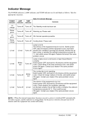
... orange Blinks green Lit green Blinks orange Lit red Lit red Lit red Lit red LAMP indicator Turns off Turns off Turns off Turns off Lit red Blinks red Turns off Turns off TEMP indicator Turns off Turns off Turns off Turns off Turns off Turns off Blinks red Lit red Table 10: Indicator Message Contents The Standby mode has been set. Normal operation possible. Contact your dealer if the same problem occurs again. Switch power OFF, wait 20 minutes until the equipment cools. Warming up. The interior of the lamp and lamp cover...
... orange Blinks green Lit green Blinks orange Lit red Lit red Lit red Lit red LAMP indicator Turns off Turns off Turns off Turns off Lit red Blinks red Turns off Turns off TEMP indicator Turns off Turns off Turns off Turns off Turns off Turns off Blinks red Lit red Table 10: Indicator Message Contents The Standby mode has been set. Normal operation possible. Contact your dealer if the same problem occurs again. Switch power OFF, wait 20 minutes until the equipment cools. Warming up. The interior of the lamp and lamp cover...

User Guide
Page 24
... present but no audio. Adjust the video. Adjust the focus or H PHASE. If the situation cannot be corrected, then contact your dealer. Video is out of its service life. Video is still attached. Use the projector or remote control transmitter to minimum. No signal input. Connect correctly. Symptom The power is set to set . Plug the power cord into an AC power outlet. Connect correctly. Connect correctly. Press the MUTE button. Replace with the MENU button and the...
... present but no audio. Adjust the video. Adjust the focus or H PHASE. If the situation cannot be corrected, then contact your dealer. Video is out of its service life. Video is still attached. Use the projector or remote control transmitter to minimum. No signal input. Connect correctly. Symptom The power is set to set . Plug the power cord into an AC power outlet. Connect correctly. Connect correctly. Press the MUTE button. Replace with the MENU button and the...
User Guide
Page 27
... of nature, unauthorized product modification, or failure to be defective in material and workmanship during the warranty period, ViewSonic will need to a product defect. 3. Projector Warranty (V2.1) Release Date: 04-18-2001 ViewSonic PJ1065 25 e. Normal wear and tear. Removal, installation, and set-up service charges. You will at its products to follow instructions supplied with a like product. DAMAGE TO OTHER...
... of nature, unauthorized product modification, or failure to be defective in material and workmanship during the warranty period, ViewSonic will need to a product defect. 3. Projector Warranty (V2.1) Release Date: 04-18-2001 ViewSonic PJ1065 25 e. Normal wear and tear. Removal, installation, and set-up service charges. You will at its products to follow instructions supplied with a like product. DAMAGE TO OTHER...

User Guide
Page 29
... used , use grounded power supply cord and the provided shielded video interface cable with bonded ferrite cores. User Information for a Class B digital device, pursuant to part 15 of FCC (Federal Communication Commission) equipment provided that interference will not occur in a residential installation. AVIS: Cet appeil numerique de la Classe B conforme a la norme NMB-003 du Canada. FCC Warning To assure continued FCC...
... used , use grounded power supply cord and the provided shielded video interface cable with bonded ferrite cores. User Information for a Class B digital device, pursuant to part 15 of FCC (Federal Communication Commission) equipment provided that interference will not occur in a residential installation. AVIS: Cet appeil numerique de la Classe B conforme a la norme NMB-003 du Canada. FCC Warning To assure continued FCC...


