

Service Manual
Page 2
... make changes from time to time in any form or by ViewSonic Corporation. Trademarks ViewSonic is a registered trademark of their respective owners. All rights reserved. No part of this document are the property of ViewSonic Corporation. Copyright Copyright © 1998 by any means, electronic, mechanical, magnetic, optical, chemical, manual or otherwise, without obligation of ViewSonic to the contents hereof and specifically...
... make changes from time to time in any form or by ViewSonic Corporation. Trademarks ViewSonic is a registered trademark of their respective owners. All rights reserved. No part of this document are the property of ViewSonic Corporation. Copyright Copyright © 1998 by any means, electronic, mechanical, magnetic, optical, chemical, manual or otherwise, without obligation of ViewSonic to the contents hereof and specifically...

Service Manual
Page 3
REPLACEMENT PARTS LIST 1 2 2 3-6 7-9 10-17 18-20 21 22-23 24 25-42 43-44 45-46 47-48 iii PJ1000 Service Manual ADJUSTMENTS 5. BLOCK DIAGRAM 9. NAMES OF EACH PART 4. SERVICE POINTS 7. CLEANING 8. SPECIFICATIONS 3. INTERCONNECTION DIAGRAM 12. TABLE OF CONTENTS SERVICE WARNING 1. WIRING DIAGRAM 10. SCHEMATIC DIAGRAMS 11. DISSASSEMBLY DIAGRAMS 13. PRODUCT FEATURES 2. TROUBLESHOOTING 6.
REPLACEMENT PARTS LIST 1 2 2 3-6 7-9 10-17 18-20 21 22-23 24 25-42 43-44 45-46 47-48 iii PJ1000 Service Manual ADJUSTMENTS 5. BLOCK DIAGRAM 9. NAMES OF EACH PART 4. SERVICE POINTS 7. CLEANING 8. SPECIFICATIONS 3. INTERCONNECTION DIAGRAM 12. TABLE OF CONTENTS SERVICE WARNING 1. WIRING DIAGRAM 10. SCHEMATIC DIAGRAMS 11. DISSASSEMBLY DIAGRAMS 13. PRODUCT FEATURES 2. TROUBLESHOOTING 6.

Service Manual
Page 4
... this manual before servicing. • Service Warning 1. Be sure to read this liquid crystal projector. Never touch the lamp bulb with a high voltage circuit for the lamp. Do not touch the exhaust fan, during operation. 5. When replace the lamp, to avoid burns to maintain safety before servicing. Caution Be sure to be damaged. They may cause bursting of the LCD module ass'y. • ViewSonic Corporation - 1 - If replacing...
... this manual before servicing. • Service Warning 1. Be sure to read this liquid crystal projector. Never touch the lamp bulb with a high voltage circuit for the lamp. Do not touch the exhaust fan, during operation. 5. When replace the lamp, to avoid burns to maintain safety before servicing. Caution Be sure to be damaged. They may cause bursting of the LCD module ass'y. • ViewSonic Corporation - 1 - If replacing...

Service Manual
Page 5
... system I -IN composite, TTL level Audio Input Output Speaker output Power supply Power consumption 200mVrms, 20kQ or less 0-200mVrrns, lkil 2W + 2W (stereo) AC100-120V/5A,AC220-240V/2.2A (50/60Hz) 370W Dimensions 404 (W) x 162 (H) x 312 (D) mm Weight 9.1kg Temperature range Operation Storage : 0-35"C : -20-60"C Accessories Remote control Batteries LR6 Power cord Stereo mini cable MAC adapter 1 RGB signal cable 1 2 Video/Audio cable 1 3 Mouse cable 3 1 S-Video cable 1 1 ViewSonic Corporation - 2 - : Confidential • Do...
... system I -IN composite, TTL level Audio Input Output Speaker output Power supply Power consumption 200mVrms, 20kQ or less 0-200mVrrns, lkil 2W + 2W (stereo) AC100-120V/5A,AC220-240V/2.2A (50/60Hz) 370W Dimensions 404 (W) x 162 (H) x 312 (D) mm Weight 9.1kg Temperature range Operation Storage : 0-35"C : -20-60"C Accessories Remote control Batteries LR6 Power cord Stereo mini cable MAC adapter 1 RGB signal cable 1 2 Video/Audio cable 1 3 Mouse cable 3 1 S-Video cable 1 1 ViewSonic Corporation - 2 - : Confidential • Do...
Service Manual
Page 6
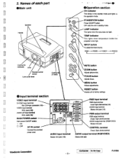
...N1116:1e4 LAMP indicator This lights when the lamp does not light \O 0,0 TEMP indicator This lights when temperature inside the projector Is too high. RGB1-P.RGB2 VIDE01 VIDEO2 4 Cooling fan (exhaust) Lens Remote control sensor Lens cover lever Cooling (in standby mode. MENU button Picture adjustments. RESET button Resets unit to factory settings. • Input terminal section VIDEO input terminal S-VIDEO input terminal Mini DIN-4pin connector (12) VIDEO input terminal • RCA Jack (1/2 AUDIO UR input terminal RCA Jack clay MAIN POWER switch Main power ON/OFF switch. WA...
...N1116:1e4 LAMP indicator This lights when the lamp does not light \O 0,0 TEMP indicator This lights when temperature inside the projector Is too high. RGB1-P.RGB2 VIDE01 VIDEO2 4 Cooling fan (exhaust) Lens Remote control sensor Lens cover lever Cooling (in standby mode. MENU button Picture adjustments. RESET button Resets unit to factory settings. • Input terminal section VIDEO input terminal S-VIDEO input terminal Mini DIN-4pin connector (12) VIDEO input terminal • RCA Jack (1/2 AUDIO UR input terminal RCA Jack clay MAIN POWER switch Main power ON/OFF switch. WA...
Service Manual
Page 7
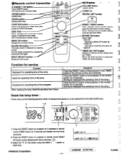
... BLANK. ZOOM button Adjusts picture size. •Remote control transmitter STANDBY / ON button Power ON/OFF button. OFF sets the unit in standby more. DISK PAD When displays the on-screen menus, selects or adjusts the menu items. When removes the on-screen menus, MENU ON button Displays the on projector for 3 seconds or remote control TIMER button for service Function Displayed the operating time of the lamp Reset the operating time of the lamp Displayed the operating time of the projector When replacing the lamp, Reset the operating time of the projector or the remote control, for...
... BLANK. ZOOM button Adjusts picture size. •Remote control transmitter STANDBY / ON button Power ON/OFF button. OFF sets the unit in standby more. DISK PAD When displays the on-screen menus, selects or adjusts the menu items. When removes the on-screen menus, MENU ON button Displays the on projector for 3 seconds or remote control TIMER button for service Function Displayed the operating time of the lamp Reset the operating time of the lamp Displayed the operating time of the projector When replacing the lamp, Reset the operating time of the projector or the remote control, for...
Service Manual
Page 8
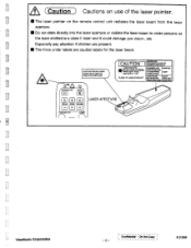
... are caution labels for the laser beam. WIFACTSSA Elea].UDRPASSE I MACEillDWI /STANDBY/ON MUTE (or (43(1 co. co.) 1=)] = 1 FOCUS ZOOM VOLUME POSITION ON hASER LASER APERTURE ViewSonic Corporation - 5 - Do Not Copy PJ1000 Confidential - AVOID EXPOSURE-LASER RADIATION IS EMITTED FROM THIS APERTURE CAUTION * ... OMS LE FAISCDUIPWIEL MASSICEOADE 2 USERSIPMUM RA[X CF MOW DBISTRIM. A (Caution ) Cautions on use of the laser pointer. • The laser pointer on the remote control unit radiates the laser beam from the laser aperture. • Do not state directly into the...
... are caution labels for the laser beam. WIFACTSSA Elea].UDRPASSE I MACEillDWI /STANDBY/ON MUTE (or (43(1 co. co.) 1=)] = 1 FOCUS ZOOM VOLUME POSITION ON hASER LASER APERTURE ViewSonic Corporation - 5 - Do Not Copy PJ1000 Confidential - AVOID EXPOSURE-LASER RADIATION IS EMITTED FROM THIS APERTURE CAUTION * ... OMS LE FAISCDUIPWIEL MASSICEOADE 2 USERSIPMUM RA[X CF MOW DBISTRIM. A (Caution ) Cautions on use of the laser pointer. • The laser pointer on the remote control unit radiates the laser beam from the laser aperture. • Do not state directly into the...
Service Manual
Page 9
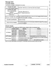
... message will blink, and the power will light or blink in the following cases. NO INPUT IS DETECTED Signal is not input. PJ100b Indicator display The ON indicator, LAMP indicator and TEMP indicator will turns off after 10 minutes. Blinking of the projector, it cannot be recovered, contact your dealer. PERSON." Lights red TEMP indicator Blinks red Correctly reinstall so as not to be changed. Indicator status Meaning Remedy Lights green Standby mode Blinks green ON indicator Lights green During warming up During operation Blinks green During cooling down LAMP indicator...
... message will blink, and the power will light or blink in the following cases. NO INPUT IS DETECTED Signal is not input. PJ100b Indicator display The ON indicator, LAMP indicator and TEMP indicator will turns off after 10 minutes. Blinking of the projector, it cannot be recovered, contact your dealer. PERSON." Lights red TEMP indicator Blinks red Correctly reinstall so as not to be changed. Indicator status Meaning Remedy Lights green Standby mode Blinks green ON indicator Lights green During warming up During operation Blinks green During cooling down LAMP indicator...
Service Manual
Page 11
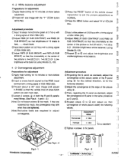
... a standard ©Tighten 4 screws to fix panels. Fig.4 - 1 ViewSonic Corporation See Fig.4 - 2 - 8- 4 - 2 White balance adjustment Preparations for adjustment ©Apply heat-running for 10 minutes or more before adjustment. ()Project 40" size image with the "+" ZOOM button set the picture adjustment to I NORMAL. ®Press the MENU button and select 'N" of COLOR BAL. ©Input white pattem at 0.52Vp-p with a timing signal of XGA VESA (60). ©Project about a 40" size image and adjust H.PHASE so that the...
... a standard ©Tighten 4 screws to fix panels. Fig.4 - 1 ViewSonic Corporation See Fig.4 - 2 - 8- 4 - 2 White balance adjustment Preparations for adjustment ©Apply heat-running for 10 minutes or more before adjustment. ()Project 40" size image with the "+" ZOOM button set the picture adjustment to I NORMAL. ®Press the MENU button and select 'N" of COLOR BAL. ©Input white pattem at 0.52Vp-p with a timing signal of XGA VESA (60). ©Project about a 40" size image and adjust H.PHASE so that the...

Service Manual
Page 13
... ass'y NO signal set to the Power NO unit? Light Not light Change the lamp Not light Is pin (Dot EBAR on the PWB easy signal? 5. YES 'If =5V Power unit (ballast) Light Lamp Power unit (ballast) PWB ass'y signal ViewSonic Corporation - 10 - Confidential- YES • AC inlet Powe switch PWB ass'y filter Are voltage input at p ns 2, 3, NO ®, 2 of LAMP indicator? Troubleshooting .( Power can not be turned on Is the input voltage applied...
... ass'y NO signal set to the Power NO unit? Light Not light Change the lamp Not light Is pin (Dot EBAR on the PWB easy signal? 5. YES 'If =5V Power unit (ballast) Light Lamp Power unit (ballast) PWB ass'y signal ViewSonic Corporation - 10 - Confidential- YES • AC inlet Powe switch PWB ass'y filter Are voltage input at p ns 2, 3, NO ®, 2 of LAMP indicator? Troubleshooting .( Power can not be turned on Is the input voltage applied...

Service Manual
Page 17
... at pins ®, t, 0 of PSD5 on the PWB ass'y drive? YES See page 14 LCD module ass'y PWB ass'y signal PWB ass)* signal PWB ass'y drive PWB ass'y drive ViewSonic Corporation - 14 - e YES V sync H sync 8 signal ® 0 G signal Ae 0 R signal serial data input NO at each pin of P501, P601, NO P701 on the PWB ass'y drive? Do Not Copy PJ1C20 Confidential...
... at pins ®, t, 0 of PSD5 on the PWB ass'y drive? YES See page 14 LCD module ass'y PWB ass'y signal PWB ass)* signal PWB ass'y drive PWB ass'y drive ViewSonic Corporation - 14 - e YES V sync H sync 8 signal ® 0 G signal Ae 0 R signal serial data input NO at each pin of P501, P601, NO P701 on the PWB ass'y drive? Do Not Copy PJ1C20 Confidential...

Service Manual
Page 21
... new lamp, reset the operating time of the LCD module ass'y. 5. Turn the power off and let the projector cool. Remove 3 screws B5 and remove the LCD module ass'y. (4) Removing the front cover ass'y and exhaust fan. 1. Remove 5 screws B1 and remove the upper case ass'y and disconnect the operation panel connector. 2. Remove 2 screws B4 and remove the DC motor ass'y from PWB ass'y signal. 4 Remove 4 screws B7 and remove the exhaust fan. Remove the lens prism unit with DC motors. 4. Service...
... new lamp, reset the operating time of the LCD module ass'y. 5. Turn the power off and let the projector cool. Remove 3 screws B5 and remove the LCD module ass'y. (4) Removing the front cover ass'y and exhaust fan. 1. Remove 5 screws B1 and remove the upper case ass'y and disconnect the operation panel connector. 2. Remove 2 screws B4 and remove the DC motor ass'y from PWB ass'y signal. 4 Remove 4 screws B7 and remove the exhaust fan. Remove the lens prism unit with DC motors. 4. Service...

Service Manual
Page 22
...'y input terminal. (1) Removing the Power unit (ballast). 1. Remove the upper case ass'y. (Refer to step 1 to 2 of item 6 - 2 (1).) O 2. Remove screw C5 and remove the ground connection wire. Disconnect 2 connectors and remove the power unit (circuit). (5) Removing the lens shutter unit. 1. Remove the front cover ass'y. '1'- (Refer to 2 of item 6 - 2 (1).) e Screw driver 2. Remove the upper case ass'y. (Refer to step 1 to Item 6 - 2 (4).) 2. Disconnect 4 connectors. 4. inside (3) Removing the PWB ass'y filter...
...'y input terminal. (1) Removing the Power unit (ballast). 1. Remove the upper case ass'y. (Refer to step 1 to 2 of item 6 - 2 (1).) O 2. Remove screw C5 and remove the ground connection wire. Disconnect 2 connectors and remove the power unit (circuit). (5) Removing the lens shutter unit. 1. Remove the front cover ass'y. '1'- (Refer to 2 of item 6 - 2 (1).) e Screw driver 2. Remove the upper case ass'y. (Refer to step 1 to Item 6 - 2 (4).) 2. Disconnect 4 connectors. 4. inside (3) Removing the PWB ass'y filter...

Service Manual
Page 23
.... 3. Remove the power unit (filter). (Refer to 3 of itmen 6 - 2 (2).) 2. Remove the PWB ass'y input terminal RGB. (Refer to item 6 - 3 (5).) 4. Do Not Copy PJ10 ) Remove 2 screws D5 and remove I /O terminal holder. 4.Remove screw C8 and remove the ground connction wire from the PWB ass'y signal. 3.Remove 4 screws D4 and remove the intake fan. (4) Removing the PWB ass'y mother. 1. Remove screw D1 and remove the micro switch and thermal censor switch. 3.Remove 4 screws D2 and remove the...
.... 3. Remove the power unit (filter). (Refer to 3 of itmen 6 - 2 (2).) 2. Remove the PWB ass'y input terminal RGB. (Refer to item 6 - 3 (5).) 4. Do Not Copy PJ10 ) Remove 2 screws D5 and remove I /O terminal holder. 4.Remove screw C8 and remove the ground connction wire from the PWB ass'y signal. 3.Remove 4 screws D4 and remove the intake fan. (4) Removing the PWB ass'y mother. 1. Remove screw D1 and remove the micro switch and thermal censor switch. 3.Remove 4 screws D2 and remove the...
Service Manual
Page 24
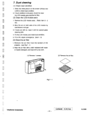
... a dry cloth. (1) Remove 1 screws. Dust cleaning (1) Check dust condition 1. Show the white picture on the screen (whose size is not good, should be clean the LCD module ass'y and the Air filter. (2) Clean the LCD module ass'y 1. Fix the LCD module, and check dust condition. 5. If dusts are still on both side of the projector. (see 4 - 3) (3) Clean the air filter 1. iv • L (2) Remove the air filter. • • • • • Fig.7 - 1 ViewSonic Corporation - 21...
... a dry cloth. (1) Remove 1 screws. Dust cleaning (1) Check dust condition 1. Show the white picture on the screen (whose size is not good, should be clean the LCD module ass'y and the Air filter. (2) Clean the LCD module ass'y 1. Fix the LCD module, and check dust condition. 5. If dusts are still on both side of the projector. (see 4 - 3) (3) Clean the air filter 1. iv • L (2) Remove the air filter. • • • • • Fig.7 - 1 ViewSonic Corporation - 21...

Service Manual
Page 28
... _ 100/16 T A34/SG.XGA-DRIVE/DRIVE/SHEET-1 I 1 18060031... 8635 1 OP PH101 1,501511 2 COVERS.W 1806037 1822 2P PNIVI TEMPS.W - 0;LI 111661/.4431 O (.2)... (2) (-9 (.5) (7..)CO 02) F11,6,23 D06IC02II4EX ONO L623 5 . ;12(43 DD6A0P32O2K raf 01R150O6340088vC1C6225L6*T21T4-628 PH 1511A2T?PTdEN5T2I0N 3 +120 2 0 THERMAL L626 CEO O GND R1060m0[4,40001..[17166500023 C LFEONCSU-OO1 RENS 1K to 8621 1104041 -.C637 -0.01 PO5 PP1OO62W00E7VRFZAINI 8 IEPD)F2P68101 L661 POWER...ViewSonic Corporation - 25- Do Not Copy PJ1000 Confidential -
... _ 100/16 T A34/SG.XGA-DRIVE/DRIVE/SHEET-1 I 1 18060031... 8635 1 OP PH101 1,501511 2 COVERS.W 1806037 1822 2P PNIVI TEMPS.W - 0;LI 111661/.4431 O (.2)... (2) (-9 (.5) (7..)CO 02) F11,6,23 D06IC02II4EX ONO L623 5 . ;12(43 DD6A0P32O2K raf 01R150O6340088vC1C6225L6*T21T4-628 PH 1511A2T?PTdEN5T2I0N 3 +120 2 0 THERMAL L626 CEO O GND R1060m0[4,40001..[17166500023 C LFEONCSU-OO1 RENS 1K to 8621 1104041 -.C637 -0.01 PO5 PP1OO62W00E7VRFZAINI 8 IEPD)F2P68101 L661 POWER...ViewSonic Corporation - 25- Do Not Copy PJ1000 Confidential -

Service Manual
Page 29
...n,o0000 g g UvU000 6 6 6H.c 0904 1001 2 - Do Not Copy PJ1000 U of C704 0. 1 FT 9722 27K - C 50 VCOHOFST g ;v, N.0...N.0 : .10c-1N S/12-CNT SID_IN S/12_CNT 8844 (21251 9824 0 N.0 SID_OFST VCC FRP 91'7,:104UT VIDEO.IN OFFSET 9' P$ 1002 CX42112R N.0 N.0 N.0 F/R_CHT NEXT_IN NEXT_OUT ' , z ,,F POS_cNT2 1 ,j POS... N.0 R724 0 vCC FRP 5H-1N Div _OUT IDEO-IN OFF,SET 6 6, GPO F/R-CNT NEXT_IN NEXT_OUT z = POS-CNT2 X POS...01 2731 JO C719 0.01_4 --I 0718 0.01 F A34/SG.XGA-DRIVE/DRIVE/SHEET-2 1 I 7 (2/3 9 ViewSonic Corporation - 26 - BK 9939 0 WI 6930 108-8 ;2 01...
...n,o0000 g g UvU000 6 6 6H.c 0904 1001 2 - Do Not Copy PJ1000 U of C704 0. 1 FT 9722 27K - C 50 VCOHOFST g ;v, N.0...N.0 : .10c-1N S/12-CNT SID_IN S/12_CNT 8844 (21251 9824 0 N.0 SID_OFST VCC FRP 91'7,:104UT VIDEO.IN OFFSET 9' P$ 1002 CX42112R N.0 N.0 N.0 F/R_CHT NEXT_IN NEXT_OUT ' , z ,,F POS_cNT2 1 ,j POS... N.0 R724 0 vCC FRP 5H-1N Div _OUT IDEO-IN OFF,SET 6 6, GPO F/R-CNT NEXT_IN NEXT_OUT z = POS-CNT2 X POS...01 2731 JO C719 0.01_4 --I 0718 0.01 F A34/SG.XGA-DRIVE/DRIVE/SHEET-2 1 I 7 (2/3 9 ViewSonic Corporation - 26 - BK 9939 0 WI 6930 108-8 ;2 01...
Service Manual
Page 46
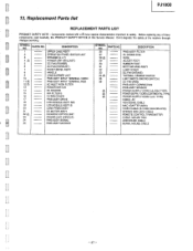
... FILTER POWER SWITCH I/O HOLDER AIR FILTER B FILTER COVER PWB ASS'Y DRIVE LCD MODULE ASS'Y R/G LCD MODULE ASS'Y B LENS PRISM ASS'Y DC MOTOR ASS'Y DICHROIC OPTICS UNIT POWER UNIT (CIRCUIT) PWB ASS'Y SIGNAL PWB ASS'Y MOTHER SYMBOL NO. TYPE) CABLE. Don't degrade the safety of this Service Manual. Before replacing any of there components, read carefully, the PRODUCT SAFETY NOTICE of the receiver through improper servicing. PARTS NO. AV VGA SIGNAL CABLE MAC ADAPTER...
... FILTER POWER SWITCH I/O HOLDER AIR FILTER B FILTER COVER PWB ASS'Y DRIVE LCD MODULE ASS'Y R/G LCD MODULE ASS'Y B LENS PRISM ASS'Y DC MOTOR ASS'Y DICHROIC OPTICS UNIT POWER UNIT (CIRCUIT) PWB ASS'Y SIGNAL PWB ASS'Y MOTHER SYMBOL NO. TYPE) CABLE. Don't degrade the safety of this Service Manual. Before replacing any of there components, read carefully, the PRODUCT SAFETY NOTICE of the receiver through improper servicing. PARTS NO. AV VGA SIGNAL CABLE MAC ADAPTER...
Service Manual
Page 47
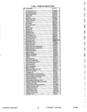
... Power Supply Cord (UK tyep) EV00341 45 Instruction Manual QR24991 46 3 Conductor Video/Audio Cable EW10933 47 RGB-D Cable(15Pin Male to 15Pin Male) EW04101 48 Apple MAC Adapter EY0D641 49 Video Cable (S-video Mini DIN 4PIN) EW10992 50 Stereo Mini Jack Cable EW02601 51 Remote Control Unit HL0D892 52 PS/2 Mouse Cable EW02752 53 ADB-2 Mouse Cable EW02742 54 Serial-2 Mouse Cable EW02732 55 COVER JIG NX02971 ViewSonic Corporation - 48 - : Confidential - PJ1000 Projector Spare Parts...
... Power Supply Cord (UK tyep) EV00341 45 Instruction Manual QR24991 46 3 Conductor Video/Audio Cable EW10933 47 RGB-D Cable(15Pin Male to 15Pin Male) EW04101 48 Apple MAC Adapter EY0D641 49 Video Cable (S-video Mini DIN 4PIN) EW10992 50 Stereo Mini Jack Cable EW02601 51 Remote Control Unit HL0D892 52 PS/2 Mouse Cable EW02752 53 ADB-2 Mouse Cable EW02742 54 Serial-2 Mouse Cable EW02732 55 COVER JIG NX02971 ViewSonic Corporation - 48 - : Confidential - PJ1000 Projector Spare Parts...

Service Manual
Page 48
... Service Providers (FYI) Model # : PJ1000 Subject: Product upgrade to reduce red color convergence errors in the USA at (909) 444-8727. If you have any questions regarding this service bulletin, please contact the Quality Assurance Department in the corners and therefore improve focus. Change(s)/Countermeasure(s): Part number will remain the same: Part Location Part Description Part Number Lens Prism Assembly M-MS-0808-1706 Repair Action Upgrade when necessary Field Disposition: Factory...
... Service Providers (FYI) Model # : PJ1000 Subject: Product upgrade to reduce red color convergence errors in the USA at (909) 444-8727. If you have any questions regarding this service bulletin, please contact the Quality Assurance Department in the corners and therefore improve focus. Change(s)/Countermeasure(s): Part number will remain the same: Part Location Part Description Part Number Lens Prism Assembly M-MS-0808-1706 Repair Action Upgrade when necessary Field Disposition: Factory...


