Operation Manual
Page 12
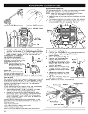
...travel while looking in . Start the engine and let it run at the top of operation. • The engine must be cold when checking or adjusting the valve clearance. • This task should be performed inside, in between the air filter cover and the engine starter housing (Fig. 29). Refer to warm...the piston to Oil and Fuel Information. Refer to the top of engine power Have the carburetor adjusted by turning a 5/8 in the spark plug hole (Fig. 32). • Both rocker arms move freely, and both valves are closed. Clean Air Filter The condition of the air filter is a loss of its ...
...travel while looking in . Start the engine and let it run at the top of operation. • The engine must be cold when checking or adjusting the valve clearance. • This task should be performed inside, in between the air filter cover and the engine starter housing (Fig. 29). Refer to warm...the piston to Oil and Fuel Information. Refer to the top of engine power Have the carburetor adjusted by turning a 5/8 in the spark plug hole (Fig. 32). • Both rocker arms move freely, and both valves are closed. Clean Air Filter The condition of the air filter is a loss of its ...
Operation Manual
Page 13
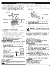
... strong detergents. Allow the engine to distribute the oil. Measure the clearance between the rocker arm and the valve return spring. See Figures 32 and 33. Turn the adjusting nut (Fig. 33) using a torque wrench torque to: 110-120 in accordance to clean off any loose...34). 5. Turn the 5/8 in accordance to run until snug. Grit in . (.076-.152 mm) Intake Valve Stem Feeler Gauge Valve Stem Fig. 33 8. WARNING: To avoid serious personal injury, always turn the adjusting nut clockwise. Thoroughly clean the unit and inspect for storage. Slide the feeler gauge between the...
... strong detergents. Allow the engine to distribute the oil. Measure the clearance between the rocker arm and the valve return spring. See Figures 32 and 33. Turn the adjusting nut (Fig. 33) using a torque wrench torque to: 110-120 in accordance to clean off any loose...34). 5. Turn the 5/8 in accordance to run until snug. Grit in . (.076-.152 mm) Intake Valve Stem Feeler Gauge Valve Stem Fig. 33 8. WARNING: To avoid serious personal injury, always turn the adjusting nut clockwise. Thoroughly clean the unit and inspect for storage. Slide the feeler gauge between the...


