
Operation Manual
Page 1
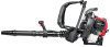
... the information for Safe Operation 2 Know Your Unit 5 Assembly Instructions 6 Oil and Fuel 8 Starting/Stopping Instructions 9 Operating Instructions 10 Maintenance and Repair Instructions 11 Cleaning and Storage 13 Troubleshooting 14 Specifications 15 Warranty Information 18 Parts List E18 P/N 769-03148C Copy the model and parent part number here: Copy the serial number here: All information, illustrations, and specifications in Canada to make changes at the time of printing. Operator's Manual 4-Cycle Backpack Blower TB4BP SAVE THESE INSTRUCTIONS For service call 1-800-828...
... the information for Safe Operation 2 Know Your Unit 5 Assembly Instructions 6 Oil and Fuel 8 Starting/Stopping Instructions 9 Operating Instructions 10 Maintenance and Repair Instructions 11 Cleaning and Storage 13 Troubleshooting 14 Specifications 15 Warranty Information 18 Parts List E18 P/N 769-03148C Copy the model and parent part number here: Copy the serial number here: All information, illustrations, and specifications in Canada to make changes at the time of printing. Operator's Manual 4-Cycle Backpack Blower TB4BP SAVE THESE INSTRUCTIONS For service call 1-800-828...
Operation Manual
Page 2
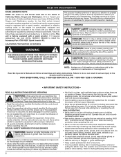
... and safety instructions. Never allow children to obey a safety warning can explode if ignited. Never operate the unit without the fuel cap securely in the states of California (Public Resources Codes 4442 and 4443), Oregon and Washington require, by themselves eliminate any spilled fuel from oil and fuel. • Avoid accidental starting position whenever pulling the starter rope. WHILE OPERATING • Never start the engine until fuel vapors...
... and safety instructions. Never allow children to obey a safety warning can explode if ignited. Never operate the unit without the fuel cap securely in the states of California (Public Resources Codes 4442 and 4443), Oregon and Washington require, by themselves eliminate any spilled fuel from oil and fuel. • Avoid accidental starting position whenever pulling the starter rope. WHILE OPERATING • Never start the engine until fuel vapors...
Operation Manual
Page 3
... grass, leaves, excessive grease or carbon build up by the air intake and thrown out by a Troy-Bilt outlet. SPECIAL NOTE: Exposure to vibrations through prolonged use of this unit for maintenance, repair, to prevent unauthorized use , see Cleaning and Storage instructions. • Keep these problems. Users who operate power tools on any object into contact with a foreign object, stop the engine immediately and check for damage. These parts...
... grass, leaves, excessive grease or carbon build up by the air intake and thrown out by a Troy-Bilt outlet. SPECIAL NOTE: Exposure to vibrations through prolonged use of this unit for maintenance, repair, to prevent unauthorized use , see Cleaning and Storage instructions. • Keep these problems. Users who operate power tools on any object into contact with a foreign object, stop the engine immediately and check for damage. These parts...

Operation Manual
Page 4
... needed . • CHOKE CONTROL 1. • FULL choke position 2. • PARTIAL choke position 3. • RUN choke position • HOT SURFACE WARNING Do not touch a hot surface. Wear eye protection meeting ANSI Z87.1 standards and ear protection when operating this unit. They remain hot for complete safety, assembly, operating, maintenance,` and repair information. You may appear on this unit. Read the operator's manual for a short time after the unit is turned...
... needed . • CHOKE CONTROL 1. • FULL choke position 2. • PARTIAL choke position 3. • RUN choke position • HOT SURFACE WARNING Do not touch a hot surface. Wear eye protection meeting ANSI Z87.1 standards and ear protection when operating this unit. They remain hot for complete safety, assembly, operating, maintenance,` and repair information. You may appear on this unit. Read the operator's manual for a short time after the unit is turned...
Operation Manual
Page 5
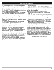
KNOW YOUR UNIT Suspension System Shoulder Support Choke Lever Air Filter Cover Starter Rope Handle Gas Cap Shoulder Support Buckle Trigger Lock Throttle Grip Trigger Stand Waist Support Clip Waist Support Throttle Cables Blower Tube Primer Bulb Muffler Nozzle Gas Tank Oil Fill Plug Elbow Tube 5
KNOW YOUR UNIT Suspension System Shoulder Support Choke Lever Air Filter Cover Starter Rope Handle Gas Cap Shoulder Support Buckle Trigger Lock Throttle Grip Trigger Stand Waist Support Clip Waist Support Throttle Cables Blower Tube Primer Bulb Muffler Nozzle Gas Tank Oil Fill Plug Elbow Tube 5

Operation Manual
Page 6
...the Flex Tube with the clamp on it over the elbow tube (Fig. 1B). 3. ASSEMBLY INSTRUCTIONS ASSEMBLING THE BLOWER TUBE WARNING: To avoid serious personal injury and damage to the upper blower tube (Fig. 2, D). Slide the end of the upper blower tube (Fig. 2, B). 3. Align the bump slot on the top end of the ... the Flex Tube (Fig. 2, A). 2. Tighten the screw on the bottom end of the second lower blower tube with the bump on the hose clamp to secure the Flex Tube to the unit, shut the unit off before removing or installing the blower tube. Align the bump slot on the end of the...
...the Flex Tube with the clamp on it over the elbow tube (Fig. 1B). 3. ASSEMBLY INSTRUCTIONS ASSEMBLING THE BLOWER TUBE WARNING: To avoid serious personal injury and damage to the upper blower tube (Fig. 2, D). Slide the end of the upper blower tube (Fig. 2, B). 3. Align the bump slot on the top end of the ... the Flex Tube (Fig. 2, A). 2. Tighten the screw on the bottom end of the second lower blower tube with the bump on the hose clamp to secure the Flex Tube to the unit, shut the unit off before removing or installing the blower tube. Align the bump slot on the end of the...

Operation Manual
Page 7
... Lower Blower Tube Fig. 8 Nozzle Fig. 6 WARNING: To avoid serious personal injury, make sure that the blower tubes are locked in place or firmly installed. 7 ASSEMBLY INSTRUCTIONS The completed blower tube should look like Figure 6. Rotate the throttle grip counterclockwise around the blower tube until its distance from the throttle grip or the engine. WARNING: Do not rotate the handle clockwise to adjust.
... Lower Blower Tube Fig. 8 Nozzle Fig. 6 WARNING: To avoid serious personal injury, make sure that the blower tubes are locked in place or firmly installed. 7 ASSEMBLY INSTRUCTIONS The completed blower tube should look like Figure 6. Rotate the throttle grip counterclockwise around the blower tube until its distance from the throttle grip or the engine. WARNING: Do not rotate the handle clockwise to adjust.
Operation Manual
Page 8
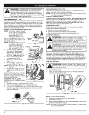
... to start the engine until it does not, fill with gasoline. Alcohol-blended fuel absorbs water. Ignited vapors may have spilled. 4. FUELING THE UNIT WARNING: Remove fuel cap slowly to Checking the Oil Level. Remove the fuel cap. 2. Gas Can Spout Fuel Tank Fig. 13 NOTE: Do not overfill the tank. 3. It can be overemphasized. Oil Fill Plug 1. Wipe up any gasoline that may explode. Using a fuel additive can keep fuel from the fueling...
... to start the engine until it does not, fill with gasoline. Alcohol-blended fuel absorbs water. Ignited vapors may have spilled. 4. FUELING THE UNIT WARNING: Remove fuel cap slowly to Checking the Oil Level. Remove the fuel cap. 2. Gas Can Spout Fuel Tank Fig. 13 NOTE: Do not overfill the tank. 3. It can be overemphasized. Oil Fill Plug 1. Wipe up any gasoline that may explode. Using a fuel additive can keep fuel from the fueling...
Operation Manual
Page 9
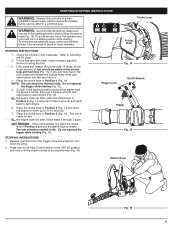
... rapid pulls to restart. Choke Lever WARNING: Avoid accidental starting position and pull the starter rope out about 4 inches, then pull 4 times in a confined area. To avoid serious personal injury, make sure that the blower tube is ready for 5-10 seconds. 7. Place the choke lever in idle. Some amount of fuel should be started in Position 2 (Fig. 14) and allow the engine to Checking the Oil Level. 2. IF... Crouch in the primer bulb and fuel lines...
... rapid pulls to restart. Choke Lever WARNING: Avoid accidental starting position and pull the starter rope out about 4 inches, then pull 4 times in a confined area. To avoid serious personal injury, make sure that the blower tube is ready for 5-10 seconds. 7. Place the choke lever in idle. Some amount of fuel should be started in Position 2 (Fig. 14) and allow the engine to Checking the Oil Level. 2. IF... Crouch in the primer bulb and fuel lines...
Operation Manual
Page 10
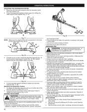
..., Monday through Saturday. • To reduce noise levels, limit the number of pieces of equipment used at any one time. • To reduce noise levels, operate power blowers at the lowest possible speed to do the job. • Check your equipment before blowing. • In dusty conditions, slightly dampen surfaces or use a mister attachment when water is in place and secure. •...
..., Monday through Saturday. • To reduce noise levels, limit the number of pieces of equipment used at any one time. • To reduce noise levels, operate power blowers at the lowest possible speed to do the job. • Check your equipment before blowing. • In dusty conditions, slightly dampen surfaces or use a mister attachment when water is in place and secure. •...
Operation Manual
Page 11
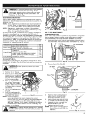
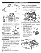
... level is an important item to a Troy-Bilt or other qualified service dealer. Remove the oil fill plug. 2. Allow ample time for the port. Replace the oil fill plug. Always service and repair a cool unit. Change the oil while the engine is in poor performance or can cause permanent damage to dry. 4. Air Filter Cover Locking Tab Fig. 23 2. MAINTENANCE AND REPAIR INSTRUCTIONS WARNING: To prevent serious injury, never perform maintenance or repairs with unit running...
... level is an important item to a Troy-Bilt or other qualified service dealer. Remove the oil fill plug. 2. Allow ample time for the port. Replace the oil fill plug. Always service and repair a cool unit. Change the oil while the engine is in poor performance or can cause permanent damage to dry. 4. Air Filter Cover Locking Tab Fig. 23 2. MAINTENANCE AND REPAIR INSTRUCTIONS WARNING: To prevent serious injury, never perform maintenance or repairs with unit running...
Operation Manual
Page 12
... arm cover with fresh fuel Fig. 29 prior to warm up. Rocker Arm Cover 6. Remove the eight (8) screws on the top of engine power Have the carburetor adjusted by turning a 5/8 in , clockwise, 1/8 of a turn at the top of adjustment carburetor. Turn the idle speed screw in . Clean dirt from the cylinder head by an authorized service dealer. 12 Fig. 30 2. Check Fuel Old fuel is at a time (as follows: 1. Rocker Arms INTAKE Adjusting Nuts EXHAUST Feeler Gauge Spark Plug...
... arm cover with fresh fuel Fig. 29 prior to warm up. Rocker Arm Cover 6. Remove the eight (8) screws on the top of engine power Have the carburetor adjusted by turning a 5/8 in , clockwise, 1/8 of a turn at the top of adjustment carburetor. Turn the idle speed screw in . Clean dirt from the cylinder head by an authorized service dealer. 12 Fig. 30 2. Check Fuel Old fuel is at a time (as follows: 1. Rocker Arms INTAKE Adjusting Nuts EXHAUST Feeler Gauge Spark Plug...
Operation Manual
Page 13
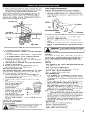
... as necessary. 9. Start the engine and allow it . 6. Change the oil, referring to distribute the oil. MAINTENANCE AND REPAIR INSTRUCTIONS 7. See Replacing the Spark Plug. 11. Grasp the plug wire firmly and pull the cap from the spark arrestor cover. 5. Set the air gap at 0.025 in . Turn the 5/8 in . (0.635 mm.) using a torque wrench torque to cool. Spark Arrestor Screen Diverter Fig. 35 T-20 Screw 3. Clean the spark arrestor screen with a soft cloth. Reinstall the spark arrestor screen, spark arrestor cover and screws. Do not use or damage...
... as necessary. 9. Start the engine and allow it . 6. Change the oil, referring to distribute the oil. MAINTENANCE AND REPAIR INSTRUCTIONS 7. See Replacing the Spark Plug. 11. Grasp the plug wire firmly and pull the cap from the spark arrestor cover. 5. Set the air gap at 0.025 in . Turn the 5/8 in . (0.635 mm.) using a torque wrench torque to cool. Spark Arrestor Screen Diverter Fig. 35 T-20 Screw 3. Clean the spark arrestor screen with a soft cloth. Reinstall the spark arrestor screen, spark arrestor cover and screws. Do not use or damage...
Operation Manual
Page 14
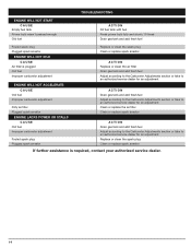
... fuel Press primer bulb fully and slowly 10 times Drain gas tank and add fresh fuel Fouled spark plug Plugged spark arrestor ENGINE WILL NOT IDLE CAUSE Air filter is plugged Old fuel Improper carburetor adjustment Replace or clean the spark plug Clean or replace spark arrestor ACTION Replace or clean the air filter Drain gas tank and add fresh fuel Adjust according to the Carburetor Adjustments section or take to an authorized service dealer for an adjustment ENGINE WILL NOT ACCELERATE CAUSE Old fuel Improper carburetor adjustment Dirty air filter Plugged spark arrestor ENGINE LACKS POWER...
... fuel Press primer bulb fully and slowly 10 times Drain gas tank and add fresh fuel Fouled spark plug Plugged spark arrestor ENGINE WILL NOT IDLE CAUSE Air filter is plugged Old fuel Improper carburetor adjustment Replace or clean the spark plug Clean or replace spark arrestor ACTION Replace or clean the air filter Drain gas tank and add fresh fuel Adjust according to the Carburetor Adjustments section or take to an authorized service dealer for an adjustment ENGINE WILL NOT ACCELERATE CAUSE Old fuel Improper carburetor adjustment Dirty air filter Plugged spark arrestor ENGINE LACKS POWER...
Operation Manual
Page 15
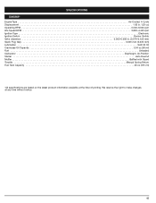
... to make changes at the time of printing. SPECIFICATIONS ENGINE* Engine Type Air-Cooled, 4-Cycle Displacement 1.95 in.3 (32 cc) Operating RPM 5,500-6,500 rpm Idle Speed RPM 3,800-4,400 rpm Ignition Type Electronic Ignition Switch Rocker Switch Valve clearance 0.003-0.006 in. (0.076-0.152 mm) Spark Plug Gap 0.025 inch (0.635 mm) Lubrication SAE 30 Oil Crankcase Oil Capacity 3.04 oz (90 ml) Fuel ...Unleaded Carburetor Diaphragm, All-Position Starter Auto Rewind Muffler Baffled with Guard Throttle Manual Spring Return Fuel Tank Capacity 20 oz...
... to make changes at the time of printing. SPECIFICATIONS ENGINE* Engine Type Air-Cooled, 4-Cycle Displacement 1.95 in.3 (32 cc) Operating RPM 5,500-6,500 rpm Idle Speed RPM 3,800-4,400 rpm Ignition Type Electronic Ignition Switch Rocker Switch Valve clearance 0.003-0.006 in. (0.076-0.152 mm) Spark Plug Gap 0.025 inch (0.635 mm) Lubrication SAE 30 Oil Crankcase Oil Capacity 3.04 oz (90 ml) Fuel ...Unleaded Carburetor Diaphragm, All-Position Starter Auto Rewind Muffler Baffled with Guard Throttle Manual Spring Return Fuel Tank Capacity 20 oz...
Operation Manual
Page 16
... of time up / fuel filter, ignition module, spark plug, and muffler. Manufacturer's Warranty Coverage • The warranty period begins on the date the engine or equipment is delivered to the retail purchaser. • The manufacturer warrants to the initial owner and each subsequent purchaser, that Troy-Bilt may be hoses, belts, connectors and other engine components caused by the use of add-on or modified parts. •...
... of time up / fuel filter, ignition module, spark plug, and muffler. Manufacturer's Warranty Coverage • The warranty period begins on the date the engine or equipment is delivered to the retail purchaser. • The manufacturer warrants to the initial owner and each subsequent purchaser, that Troy-Bilt may be hoses, belts, connectors and other engine components caused by the use of add-on or modified parts. •...
Operation Manual
Page 17
... replacement of any warranty maintenance or repairs and must be provided without charge to the owner. Emission Warranty Parts List (1) Fuel Tank Written instructions for the warranty period defined in subsection (b)(2). CALIFORNIA EVAPORATIVE EMISSION CONTROL WARRANTY STATEMENT Your Warranty Rights and Obligations The California Air Resources Board and Troy-Bilt LLC (Troy-Bilt) is pleased to explain the evaporative emission control system's warranty on your 2007 model year and later small off -road Lawn...
... replacement of any warranty maintenance or repairs and must be provided without charge to the owner. Emission Warranty Parts List (1) Fuel Tank Written instructions for the warranty period defined in subsection (b)(2). CALIFORNIA EVAPORATIVE EMISSION CONTROL WARRANTY STATEMENT Your Warranty Rights and Obligations The California Air Resources Board and Troy-Bilt LLC (Troy-Bilt) is pleased to explain the evaporative emission control system's warranty on your 2007 model year and later small off -road Lawn...
Operation Manual
Page 18
... Knobs, Outer Spools, Cutting Line, Inner Reels, Starter Pulley, Starter Ropes, Drive Belts, Saw Chain, and Chain Bar C. Box 361131 Cleveland, OH 44136-0019 No other express warranty or guaranty, whether written or oral, except as mentioned above, given by any person or entity, including a dealer or retailer, with respect to any product shall bind Troy-Bilt During the period of the Warranty, the exclusive remedy is repair or replacement...
... Knobs, Outer Spools, Cutting Line, Inner Reels, Starter Pulley, Starter Ropes, Drive Belts, Saw Chain, and Chain Bar C. Box 361131 Cleveland, OH 44136-0019 No other express warranty or guaranty, whether written or oral, except as mentioned above, given by any person or entity, including a dealer or retailer, with respect to any product shall bind Troy-Bilt During the period of the Warranty, the exclusive remedy is repair or replacement...
Operation Manual
Page 55
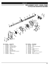
MODEL TB4BP 4-CYCLE GAS BACKPACK BLOWER 7 5 6 24 14 17 5 3 4 20 2 2 1 13 12 19 17 16 15 17 18 15 14 14 21 22 23 9 10 8 11 Item 1 2 3 4 5 6 7 8 9 10 11 12 Part No. 753-05637 753-05638 753-05652 753-05639 753-05640 753-...24 Part No. 753-05649 753-04595 753-05658 791-180050 791-181003 753-05657 791-182409 753-05661 753-05289 753-05662 753-05663 753-05660 Description Intake Cover Screw Impeller Housing Assembly Nut Screw Impeller (includes 17) Washer Throttle Retaining Clip Fuel Cap Fuel Tank Assembly (includes 21) Stand Engine Cover Assembly E19 PARTS LIST REPLACEMENT PARTS ...
MODEL TB4BP 4-CYCLE GAS BACKPACK BLOWER 7 5 6 24 14 17 5 3 4 20 2 2 1 13 12 19 17 16 15 17 18 15 14 14 21 22 23 9 10 8 11 Item 1 2 3 4 5 6 7 8 9 10 11 12 Part No. 753-05637 753-05638 753-05652 753-05639 753-05640 753-...24 Part No. 753-05649 753-04595 753-05658 791-180050 791-181003 753-05657 791-182409 753-05661 753-05289 753-05662 753-05663 753-05660 Description Intake Cover Screw Impeller Housing Assembly Nut Screw Impeller (includes 17) Washer Throttle Retaining Clip Fuel Cap Fuel Tank Assembly (includes 21) Stand Engine Cover Assembly E19 PARTS LIST REPLACEMENT PARTS ...


