Service Manual
Page 7
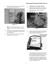
... operate over the full range of speeds. Belt Cover Figure 2.2 2.3. See Figure 2.2. See Figure 2.3. Begin with the engine running or by pulling the engine through manually. • The belt and pulley system operates whenever the engine is pressed. Remove belt cover using a 3/8" wrench. The variable speed function can be tested without pulling up the...
... operate over the full range of speeds. Belt Cover Figure 2.2 2.3. See Figure 2.2. See Figure 2.3. Begin with the engine running or by pulling the engine through manually. • The belt and pulley system operates whenever the engine is pressed. Remove belt cover using a 3/8" wrench. The variable speed function can be tested without pulling up the...
Service Manual
Page 15
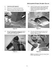
... chute to 210 - 250 inch pounds. 11 See Figure 5.4. The nuts on the flat head cap screws can be reached using a 1/2" socket, universal, and extension. Engine Impeller Figure 5.3 Figure 5.5 NOTE: On installation, torque the chipper blade to the upper housing. 5. lead from the spark plug. 5.2. Using 3/16" allen wrench, remove the... chute Figure 5.2 5.3. Self-propelled Chipper Shredder Vacuum 5.4. See Figure 5.2. Remove the black plastic nozzle as described in the BELT AND IMPELLER REMOVAL section of this manual. Disconnect H.T.
... chute to 210 - 250 inch pounds. 11 See Figure 5.4. The nuts on the flat head cap screws can be reached using a 1/2" socket, universal, and extension. Engine Impeller Figure 5.3 Figure 5.5 NOTE: On installation, torque the chipper blade to the upper housing. 5. lead from the spark plug. 5.2. Using 3/16" allen wrench, remove the... chute Figure 5.2 5.3. Self-propelled Chipper Shredder Vacuum 5.4. See Figure 5.2. Remove the black plastic nozzle as described in the BELT AND IMPELLER REMOVAL section of this manual. Disconnect H.T.


