Service Manual
Page 1
... are intended to provide supplemental information to obtain the latest materials before servicing or repairing a product. The company reserves the right to previously published versions. CSV 070 NOTE: These materials are for use by trained technicians experienced in the service and repair of outdoor power equipment of the kind described in this...
... are intended to provide supplemental information to obtain the latest materials before servicing or repairing a product. The company reserves the right to previously published versions. CSV 070 NOTE: These materials are for use by trained technicians experienced in the service and repair of outdoor power equipment of the kind described in this...

Service Manual
Page 3
TABLE OF CONTENTS Safety Switch ...1 Inspection of the Drive System 3 Transmission Removal ...5 Impeller and Belt Removal ...8 Chipper Blade Removal ...11 0
TABLE OF CONTENTS Safety Switch ...1 Inspection of the Drive System 3 Transmission Removal ...5 Impeller and Belt Removal ...8 Chipper Blade Removal ...11 0
Service Manual
Page 5
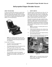
Since it will not run without a collection bag or blower chute in the switch. 1.2. This is NOT a throttle control. • The variable speed lever will not start even though the bag is to make sure that the metal tab on the collection bag or chute depress the plunger far enough to shred small yard debris. Do NOT force the lever. • The control Bail mounted to the upper impeller housing assembly. It does NOT turn-off the engine like the blade control handle on the engine.(i.e. The intent is in place. 1 The safety switch is rotating. Confirm that it 's ...
Since it will not run without a collection bag or blower chute in the switch. 1.2. This is NOT a throttle control. • The variable speed lever will not start even though the bag is to make sure that the metal tab on the collection bag or chute depress the plunger far enough to shred small yard debris. Do NOT force the lever. • The control Bail mounted to the upper impeller housing assembly. It does NOT turn-off the engine like the blade control handle on the engine.(i.e. The intent is in place. 1 The safety switch is rotating. Confirm that it 's ...
Service Manual
Page 6
NOTE: A lock tab secures the plug to reach the lock tab. 1.9. Figure 1.9 1.10. This is pressed, replace the switch. 1.6. See Figure 1.4. 1.8. The switch must be possible to run the engine without a blower chute or collector bag in place. If the switch does not break the ground path (meter reading: near 1.0 ohms, or "OL" indicates open contacts, breaking ground path) when the plunger is unsafe. 1.7. 2 Figure 1.10 Test the switch independently. Remove the switch from the magneto to ground out the magneto when the plunger is up. Figure 1.4 1.5. It should complete a path...
NOTE: A lock tab secures the plug to reach the lock tab. 1.9. Figure 1.9 1.10. This is pressed, replace the switch. 1.6. See Figure 1.4. 1.8. The switch must be possible to run the engine without a blower chute or collector bag in place. If the switch does not break the ground path (meter reading: near 1.0 ohms, or "OL" indicates open contacts, breaking ground path) when the plunger is unsafe. 1.7. 2 Figure 1.10 Test the switch independently. Remove the switch from the magneto to ground out the magneto when the plunger is up. Figure 1.4 1.5. It should complete a path...
Service Manual
Page 7
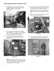
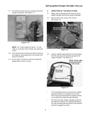
Begin with the engine running . See Figure 2.2. Inspect variable speed pulley for Belt Cover Figure 1.11 NOTE: "OL" meter reading in the wiring or the ground connection. 1.13. Run the self propel mechanism though its full range of speeds? 2.2. INSPECTION OF THE DRIVE SYSTEM 2.1. Remove belt cover using a 3/8" wrench. Self propel clutch bail Speed control lever Figure 2.3 • The crankshaft must be turning for the variable speed mechanism to respond to the control lever.This can be done with an operational test. The switch should not show continuity when the plunger ...
Begin with the engine running . See Figure 2.2. Inspect variable speed pulley for Belt Cover Figure 1.11 NOTE: "OL" meter reading in the wiring or the ground connection. 1.13. Run the self propel mechanism though its full range of speeds? 2.2. INSPECTION OF THE DRIVE SYSTEM 2.1. Remove belt cover using a 3/8" wrench. Self propel clutch bail Speed control lever Figure 2.3 • The crankshaft must be turning for the variable speed mechanism to respond to the control lever.This can be done with an operational test. The switch should not show continuity when the plunger ...
Service Manual
Page 8
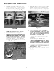
Watch the reaction of the wheel. If there is routed properly. 2.6. To check the final drive gears, remove both rear hubcaps. Check the condition of the teeth on the input shaft. Spring anchor bolt Spring Figure 2.4 NOTE: Belt removed for clarity in the transmission. Spring Belt tensioner Figure 2.7 2.8. Remove the rear wheels using a 9/16" wrench and a 1/2" wrench. 2.10. Safety switch Figure 2.6 4 Confirm that the variable speed sheave has full travel of the variable speed sheave (pulley) on the back of the two idler pulleys. Low speed position: Sheaves together...
Watch the reaction of the wheel. If there is routed properly. 2.6. To check the final drive gears, remove both rear hubcaps. Check the condition of the teeth on the input shaft. Spring anchor bolt Spring Figure 2.4 NOTE: Belt removed for clarity in the transmission. Spring Belt tensioner Figure 2.7 2.8. Remove the rear wheels using a 9/16" wrench and a 1/2" wrench. 2.10. Safety switch Figure 2.6 4 Confirm that the variable speed sheave has full travel of the variable speed sheave (pulley) on the back of the two idler pulleys. Low speed position: Sheaves together...
Service Manual
Page 9
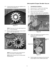
See Figure 3.4. Right side gear Drive axle Figure 3.4 3.5. This provides a ratcheting action. Pull the breaker bar rearward until the drive belt can be free to slide back and forth. TRANSMISSION REMOVAL 3.1. lead from the spark plug. 3.2. NOTE: Apply anti-sieze to pin to assure dowel pin is an "R" on the right side gear and an "L" on the correct side. Confirm that the drive gears are installed on the left side gear. 2.12. Using a 3/8" socket, remove the 3 self tapping screws securing the belt cover. See Figure 2.12. See Figure 2.11. 3. Disconnect the H.T. ...
See Figure 3.4. Right side gear Drive axle Figure 3.4 3.5. This provides a ratcheting action. Pull the breaker bar rearward until the drive belt can be free to slide back and forth. TRANSMISSION REMOVAL 3.1. lead from the spark plug. 3.2. NOTE: Apply anti-sieze to pin to assure dowel pin is an "R" on the right side gear and an "L" on the correct side. Confirm that the drive gears are installed on the left side gear. 2.12. Using a 3/8" socket, remove the 3 self tapping screws securing the belt cover. See Figure 2.12. See Figure 2.11. 3. Disconnect the H.T. ...
Service Manual
Page 10
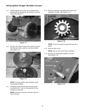
See Figure 3.10. Bushing Figure 3.12 6 See Figure 3.8. Right hand drive gear Figure 3.10 NOTE: There are removed. NOTE: The rear cross bar is also secured by the rear wheel shoulder bolts. Remove retaining ring holding drive gear and dowel pin on dust cover faces outboard 3.12. Remove E-clip and flat washer from axle. Heavy washer Dust cover E-clip Flat washer Figure 3.8 NOTE: A heavy washer goes between wheel and outside of the unit so that the rear wheels are off the ground, and remove rear hub caps. Cross-bar is shorter than the front cross bar. Using a 1/2" ...
See Figure 3.10. Bushing Figure 3.12 6 See Figure 3.8. Right hand drive gear Figure 3.10 NOTE: There are removed. NOTE: The rear cross bar is also secured by the rear wheel shoulder bolts. Remove retaining ring holding drive gear and dowel pin on dust cover faces outboard 3.12. Remove E-clip and flat washer from axle. Heavy washer Dust cover E-clip Flat washer Figure 3.8 NOTE: A heavy washer goes between wheel and outside of the unit so that the rear wheels are off the ground, and remove rear hub caps. Cross-bar is shorter than the front cross bar. Using a 1/2" ...
Service Manual
Page 11
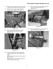
Remove three self tapping screws holding transmission brace to the frame using needle nose pliers (This is the self propel clutch cable) See Figure 3.17. See Figure 3.14. Actuating arm Self propel clutch cable Phillips screw Figure 3.14 3.15. Figure 3.17 3.18. Push the hexagonal drive axle bushings out of each side of the speed control collar. See Figure 3.18. Bushing Variable speed cable Barbed fitting Figure 3.15 3.16. Self tapping screws 3.17. NOTE: Rotating the collar counter-clockwise will aid in removal. Figure 3.18 7 Remove the two phillips screws holding the ...
Remove three self tapping screws holding transmission brace to the frame using needle nose pliers (This is the self propel clutch cable) See Figure 3.17. See Figure 3.14. Actuating arm Self propel clutch cable Phillips screw Figure 3.14 3.15. Figure 3.17 3.18. Push the hexagonal drive axle bushings out of each side of the speed control collar. See Figure 3.18. Bushing Variable speed cable Barbed fitting Figure 3.15 3.16. Self tapping screws 3.17. NOTE: Rotating the collar counter-clockwise will aid in removal. Figure 3.18 7 Remove the two phillips screws holding the ...
Service Manual
Page 12
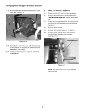
lead from the spark plug. 4.2. Using a 15/16" wrench and a 9/16" wrench remove height adjusters and cross bar. Height adjuster Cross bar Figure 4.6 NOTE: The front cross bar is longer than the rear cross bar 8 See Figure 3.19. At this manual. 4.3. Remove the transmission as described in the TRASMISSION REMOVAL section of unit to provide access to the left. Remove front wheels using an 1/2 wrench. 4.6. See Figure 4.6. Self-propelled Chipper Shredder Vacuum 3.19. Once the left side comes out, slide the transmission to the front wheel and nozzle mounting hardware. ...
lead from the spark plug. 4.2. Using a 15/16" wrench and a 9/16" wrench remove height adjusters and cross bar. Height adjuster Cross bar Figure 4.6 NOTE: The front cross bar is longer than the rear cross bar 8 See Figure 3.19. At this manual. 4.3. Remove the transmission as described in the TRASMISSION REMOVAL section of unit to provide access to the left. Remove front wheels using an 1/2 wrench. 4.6. See Figure 4.6. Self-propelled Chipper Shredder Vacuum 3.19. Once the left side comes out, slide the transmission to the front wheel and nozzle mounting hardware. ...
Service Manual
Page 13
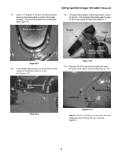
Black plastic nozzle Nozzle Engine 1/4" Screws Figure 4.7 4.8. Remove them. Remove all of black plastic nozzle toward the engine to remove. They are accessible from underneath. See Figure 4.7. 4.9. Safety gate within vacuum tube Figure 4.9 4.10. See Figure 4.10. See Figure 4.9. Self-propelled Chipper Shredder Vacuum 4.7. Tilt top of the fasteners holding the two housings together. 9 Nozzle Mounting Screws Nut & bolt Lower housing Figure 4.8 Figure 4.10 NOTE: There is a variety of the nozzle to the upper housing. Use a 1/4" wrench to remove the three ...
Black plastic nozzle Nozzle Engine 1/4" Screws Figure 4.7 4.8. Remove them. Remove all of black plastic nozzle toward the engine to remove. They are accessible from underneath. See Figure 4.7. 4.9. Safety gate within vacuum tube Figure 4.9 4.10. See Figure 4.10. See Figure 4.9. Self-propelled Chipper Shredder Vacuum 4.7. Tilt top of the fasteners holding the two housings together. 9 Nozzle Mounting Screws Nut & bolt Lower housing Figure 4.8 Figure 4.10 NOTE: There is a variety of the nozzle to the upper housing. Use a 1/4" wrench to remove the three ...
Service Manual
Page 14
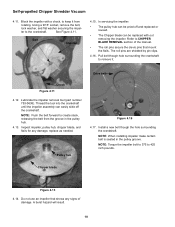
NOTE: Push the belt forward to keep it . NOTE: When installing impeller make certain belt is seated in the pulley hub. 4.13. Block the impeller with out removing the impeller. Bolt Impeller 4.15. In servicing the impeller: • The pulley hub can be replaced with a chock, to create slack, releasing the belt from rotating. Pull belt though hole surrounding the crankshaft to CHIPPER BLADE REMOVAL section of the manual. • The roll pins secure the clevis pins that shows any damage, replace as needed. NOTE: Torque the impeller bolt to 375 to the crankshaft....
NOTE: Push the belt forward to keep it . NOTE: When installing impeller make certain belt is seated in the pulley hub. 4.13. Block the impeller with out removing the impeller. Bolt Impeller 4.15. In servicing the impeller: • The pulley hub can be replaced with a chock, to create slack, releasing the belt from rotating. Pull belt though hole surrounding the crankshaft to CHIPPER BLADE REMOVAL section of the manual. • The roll pins secure the clevis pins that shows any damage, replace as needed. NOTE: Torque the impeller bolt to 375 to the crankshaft....
Service Manual
Page 15
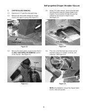
CHIPPER BLADE REMOVAL 5.1. Remove the three bolts holding the chipper chute to the impeller. Chipper chute Figure 5.2 5.3. See Figure 5.2. Self-propelled Chipper Shredder Vacuum 5.4. See Figure 5.5. See Figure 5.4. 5. Remove the black plastic nozzle as described in the BELT AND IMPELLER REMOVAL section of this manual. lead from the spark plug. 5.2. The nuts on the flat head cap screws can be reached using a 1/2" socket, universal, and extension. Using 3/16" allen wrench, remove the flat head cap screw that holds the chipper blade to the upper housing. Disconnect ...
CHIPPER BLADE REMOVAL 5.1. Remove the three bolts holding the chipper chute to the impeller. Chipper chute Figure 5.2 5.3. See Figure 5.2. Self-propelled Chipper Shredder Vacuum 5.4. See Figure 5.5. See Figure 5.4. 5. Remove the black plastic nozzle as described in the BELT AND IMPELLER REMOVAL section of this manual. lead from the spark plug. 5.2. The nuts on the flat head cap screws can be reached using a 1/2" socket, universal, and extension. Using 3/16" allen wrench, remove the flat head cap screw that holds the chipper blade to the upper housing. Disconnect ...
