Service Manual
Page 5
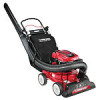
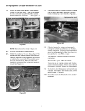
...: • All engine controls are not present, the plunger will be up, and the contacts within the switch will be closed switch. Self-propelled Chipper Shredder Vacuum Self-propelled Chipper Shredder Vacuum ABOUT THIS SECTION: In model year 2000, MTD introduced a vertical crankshaft lawn vacuum with a removable vacuum hose. Disconnect the switch from the...
...: • All engine controls are not present, the plunger will be up, and the contacts within the switch will be closed switch. Self-propelled Chipper Shredder Vacuum Self-propelled Chipper Shredder Vacuum ABOUT THIS SECTION: In model year 2000, MTD introduced a vertical crankshaft lawn vacuum with a removable vacuum hose. Disconnect the switch from the...
Service Manual
Page 6
... magneto when the plunger is up, it downward will enable the switch to ground the magneto, identify if the switch itself is up . Self-propelled Chipper Shredder Vacuum 1.4. NOTE: A lock tab secures the plug to run the engine without a blower chute or collector bag in place. The switch should show continuity with...
... magneto when the plunger is up, it downward will enable the switch to ground the magneto, identify if the switch itself is up . Self-propelled Chipper Shredder Vacuum 1.4. NOTE: A lock tab secures the plug to run the engine without a blower chute or collector bag in place. The switch should show continuity with...
Service Manual
Page 7
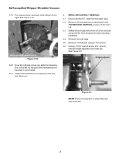
... 1 ohm. 1.12. See Figure 2.3. Mounting Bolts for Belt Cover Figure 1.11 NOTE: "OL" meter reading in Figure 1.11 indicates no continuity. See Figure 2.2. Self-propelled Chipper Shredder Vacuum 1.11.
... 1 ohm. 1.12. See Figure 2.3. Mounting Bolts for Belt Cover Figure 1.11 NOTE: "OL" meter reading in Figure 1.11 indicates no continuity. See Figure 2.2. Self-propelled Chipper Shredder Vacuum 1.11.
Service Manual
Page 8
... to the changes in one of the wheel. See Figure 2.4. Spring anchor bolt Spring Figure 2.4 NOTE: Belt removed for clarity in the transmission. Self-propelled Chipper Shredder Vacuum 2.4. Watch the travel . Confirm that connects the bail to drive the wheels when the self propel bail is an internal transmission problem, replace the...
... to the changes in one of the wheel. See Figure 2.4. Spring anchor bolt Spring Figure 2.4 NOTE: Belt removed for clarity in the transmission. Self-propelled Chipper Shredder Vacuum 2.4. Watch the travel . Confirm that connects the bail to drive the wheels when the self propel bail is an internal transmission problem, replace the...
Service Manual
Page 9
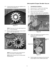
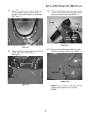
... extension into the square hole of the tensioner arm. Self tapping screws Right hand drive gear Figure 2.11 NOTE: There is in place. Self-propelled Chipper Shredder Vacuum 2.11. lead from the spark plug. 3.2. Pull the breaker bar rearward until the drive belt can be free to ensure proper ratcheting action. Remove...
... extension into the square hole of the tensioner arm. Self tapping screws Right hand drive gear Figure 2.11 NOTE: There is in place. Self-propelled Chipper Shredder Vacuum 2.11. lead from the spark plug. 3.2. Pull the breaker bar rearward until the drive belt can be free to ensure proper ratcheting action. Remove...
Service Manual
Page 10
... as the rear wheels are off the ground, and remove rear hub caps. Dust cover 4X4 supports Figure 3.7 3.8. See Figure 3.8. See Figure 3.12. Self-propelled Chipper Shredder Vacuum 3.7. Cross-bar is shorter than the front cross bar. See Figure 3.7. 3.10. See Figure 3.10. Using a 1/2" wrench and a 9/16" wrench remove the shoulder bolts...
... as the rear wheels are off the ground, and remove rear hub caps. Dust cover 4X4 supports Figure 3.7 3.8. See Figure 3.8. See Figure 3.12. Self-propelled Chipper Shredder Vacuum 3.7. Cross-bar is shorter than the front cross bar. See Figure 3.7. 3.10. See Figure 3.10. Using a 1/2" wrench and a 9/16" wrench remove the shoulder bolts...
Service Manual
Page 11
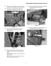
... Figure 3.14. NOTE: Rotating the collar counter-clockwise will aid in removal. Remove barbed fitting holding transmission brace to the brace. Figure 3.18 7 Self-propelled Chipper Shredder Vacuum 3.13. Push the hexagonal drive axle bushings out of each side of the speed control collar. Self tapping screws 3.17. Actuating arm Self propel...
... Figure 3.14. NOTE: Rotating the collar counter-clockwise will aid in removal. Remove barbed fitting holding transmission brace to the brace. Figure 3.18 7 Self-propelled Chipper Shredder Vacuum 3.13. Push the hexagonal drive axle bushings out of each side of the speed control collar. Self tapping screws 3.17. Actuating arm Self propel...
Service Manual
Page 12
... transmission will be solely in your hands 3.21. Remove front wheels using an 1/2 wrench. 4.6. See Figure 4.6. At this manual. 4.3. Remove the hub caps. 4.5. Self-propelled Chipper Shredder Vacuum 3.19. Install new transmission in the TRASMISSION REMOVAL section of unit to provide access to the front wheel and nozzle mounting hardware. 4.4. See Figure...
... transmission will be solely in your hands 3.21. Remove front wheels using an 1/2 wrench. 4.6. See Figure 4.6. At this manual. 4.3. Remove the hub caps. 4.5. Self-propelled Chipper Shredder Vacuum 3.19. Install new transmission in the TRASMISSION REMOVAL section of unit to provide access to the front wheel and nozzle mounting hardware. 4.4. See Figure...
Service Manual
Page 13
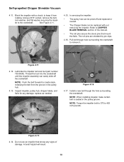
.... Black plastic nozzle Nozzle Engine 1/4" Screws Figure 4.7 4.8. Remove all of black plastic nozzle toward the engine to the lower housing. See Figure 4.10. Self-propelled Chipper Shredder Vacuum 4.7. Nozzle Mounting Screws Nut & bolt Lower housing Figure 4.8 Figure 4.10 NOTE: There is a variety of the nozzle to pass by the hose opening freely...
.... Black plastic nozzle Nozzle Engine 1/4" Screws Figure 4.7 4.8. Remove all of black plastic nozzle toward the engine to the lower housing. See Figure 4.10. Self-propelled Chipper Shredder Vacuum 4.7. Nozzle Mounting Screws Nut & bolt Lower housing Figure 4.8 Figure 4.10 NOTE: There is a variety of the nozzle to pass by the hose opening freely...
Service Manual
Page 14
... hazard will result. 10 See Figure 4.11. In servicing the impeller: • The pulley hub can be pried off the crankshaft. Refer to keep it . Chipper blade Figure 4.13 4.14. Lubricate the impeller removal tool (part number 753-0638). Do not use an impeller that mount the flails. Thread the tool.... Using a 9/16" socket, remove the bolt, lock washer, and flat washer securing the impel- The roll pins are shielded by pin clips. 4.16. Self-propelled Chipper Shredder Vacuum 4.11. Block the impeller with out removing the impeller.
... hazard will result. 10 See Figure 4.11. In servicing the impeller: • The pulley hub can be pried off the crankshaft. Refer to keep it . Chipper blade Figure 4.13 4.14. Lubricate the impeller removal tool (part number 753-0638). Do not use an impeller that mount the flails. Thread the tool.... Using a 9/16" socket, remove the bolt, lock washer, and flat washer securing the impel- The roll pins are shielded by pin clips. 4.16. Self-propelled Chipper Shredder Vacuum 4.11. Block the impeller with out removing the impeller.
Service Manual
Page 15
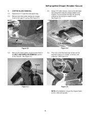
... Chipper Shredder Vacuum 5.4. Remove the black plastic nozzle as described in the BELT AND IMPELLER REMOVAL section of this manual. Engine Impeller Figure 5.3 Figure 5.5 NOTE: On installation, torque the chipper blade to the upper housing. Remove the three bolts holding the chipper ...allen wrench, remove the flat head cap screw that holds the chipper blade to the impeller. See Figure 5.3. 3/16 allen wrench Figure 5.4 5.5. Disconnect H.T. 5. CHIPPER BLADE REMOVAL 5.1. lead from the spark plug. 5.2. See Figure 5.2. Chipper chute Figure 5.2 5.3. The nuts on the flat head cap ...
... Chipper Shredder Vacuum 5.4. Remove the black plastic nozzle as described in the BELT AND IMPELLER REMOVAL section of this manual. Engine Impeller Figure 5.3 Figure 5.5 NOTE: On installation, torque the chipper blade to the upper housing. Remove the three bolts holding the chipper ...allen wrench, remove the flat head cap screw that holds the chipper blade to the impeller. See Figure 5.3. 3/16 allen wrench Figure 5.4 5.5. Disconnect H.T. 5. CHIPPER BLADE REMOVAL 5.1. lead from the spark plug. 5.2. See Figure 5.2. Chipper chute Figure 5.2 5.3. The nuts on the flat head cap ...


