
Service Manual
Page 1
...common sense when working on power equipment. All Rights Reserved. Untrained or inexperienced individuals should seek the assistance of the product's Operators Manual, supplied with the equipment. Instructions, photographs and illustrations used in this publication, and are intended to provide supplemental information to time.... reserves the right to make it may not depict actual model and component parts. © Copyright 2005 MTD Products Inc. CSV 070 NOTE: These materials are for any time to this publication, although care has been taken to make such changes to obtain the...
...common sense when working on power equipment. All Rights Reserved. Untrained or inexperienced individuals should seek the assistance of the product's Operators Manual, supplied with the equipment. Instructions, photographs and illustrations used in this publication, and are intended to provide supplemental information to time.... reserves the right to make it may not depict actual model and component parts. © Copyright 2005 MTD Products Inc. CSV 070 NOTE: These materials are for any time to this publication, although care has been taken to make such changes to obtain the...
Service Manual
Page 7
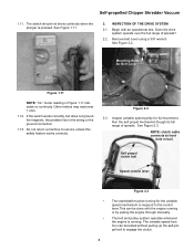
... to service unless this safety feature works correctly. The switch should not show continuity when the plunger is running or by pulling the engine through manually. • The belt and pulley system operates whenever the engine is pressed. If the switch works correctly, but does not ground the magneto, the problem...
... to service unless this safety feature works correctly. The switch should not show continuity when the plunger is running or by pulling the engine through manually. • The belt and pulley system operates whenever the engine is pressed. If the switch works correctly, but does not ground the magneto, the problem...
Service Manual
Page 12
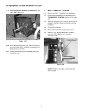
... mounting hardware. 4.4. Once the left side comes out, slide the transmission to the left. See Figure 3.19. Remove front wheels using an 1/2 wrench. 4.6. At this manual. 4.3. Disconnect the H.T. Self-propelled Chipper Shredder Vacuum 3.19.
... mounting hardware. 4.4. Once the left side comes out, slide the transmission to the left. See Figure 3.19. Remove front wheels using an 1/2 wrench. 4.6. At this manual. 4.3. Disconnect the H.T. Self-propelled Chipper Shredder Vacuum 3.19.
Service Manual
Page 14
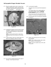
... the groove in the pulley groove. Drive belt Chock Figure 4.11 4.12. Inspect impeller, pulley hub, chipper blade, and flails for any signs of the manual. • The roll pins secure the clevis pins that mount the flails. Pull belt though hole surrounding the crankshaft to CHIPPER BLADE REMOVAL section of...
... the groove in the pulley groove. Drive belt Chock Figure 4.11 4.12. Inspect impeller, pulley hub, chipper blade, and flails for any signs of the manual. • The roll pins secure the clevis pins that mount the flails. Pull belt though hole surrounding the crankshaft to CHIPPER BLADE REMOVAL section of...
Service Manual
Page 15
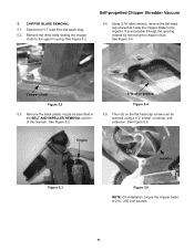
... bolts holding the chipper chute to the upper housing. Remove the black plastic nozzle as described in the BELT AND IMPELLER REMOVAL section of this manual. See Figure 5.2. It is accessible through the opening created by removing the chipper chute. lead from the spark plug. 5.2. 5. Disconnect H.T.
... bolts holding the chipper chute to the upper housing. Remove the black plastic nozzle as described in the BELT AND IMPELLER REMOVAL section of this manual. See Figure 5.2. It is accessible through the opening created by removing the chipper chute. lead from the spark plug. 5.2. 5. Disconnect H.T.


