Operation Manual
Page 1
Printed In USA TROY-BILT LLC, P.O. BOX 361131 CLEVELAND, OHIO 44136-0019 Form No. 769-08675 (November 16, 2012) FAILURE TO COMPLY WITH THESE INSTRUCTIONS MAY RESULT IN PERSONAL INJURY. Safe Operation Practices • Set-Up • Operation • Maintenance • Service • Troubleshooting • Warranty Operator's Manual Rear-Tine Tiller - Horse/Big Red WARNING READ AND FOLLOW ALL SAFETY RULES AND INSTRUCTIONS IN THIS MANUAL BEFORE ATTEMPTING TO OPERATE THIS MACHINE.
Printed In USA TROY-BILT LLC, P.O. BOX 361131 CLEVELAND, OHIO 44136-0019 Form No. 769-08675 (November 16, 2012) FAILURE TO COMPLY WITH THESE INSTRUCTIONS MAY RESULT IN PERSONAL INJURY. Safe Operation Practices • Set-Up • Operation • Maintenance • Service • Troubleshooting • Warranty Operator's Manual Rear-Tine Tiller - Horse/Big Red WARNING READ AND FOLLOW ALL SAFETY RULES AND INSTRUCTIONS IN THIS MANUAL BEFORE ATTEMPTING TO OPERATE THIS MACHINE.
Technical Manual
Page 1
a°w $12.50 OTP0111-113ILT Technical Manual PTO HORSE Tiller Models 7 HP 8 HP GARDEN WAY INC.
a°w $12.50 OTP0111-113ILT Technical Manual PTO HORSE Tiller Models 7 HP 8 HP GARDEN WAY INC.
Technical Manual
Page 2
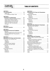
... Identifying a Bubbled Wheel Shaft Testing for a Bubbled Wheel Shaft Tightening the Castle Nut On the Wheel Speed Lever Index 5-8 5-9 5-9 5-9 5-10 5-10 5-10 5-10 6-1 6-1 6-1 6-2 6-3 6-3 6-3 6-5 6-5 7-1 7-1 7-1 7-1 7-2 7-2 7-2 7-3 7-4 7-4 7-4 8-1 a PTO HORSE MODEL TECHNICAL MANUAL 4/90 TABLE OF CONTENTS SECTION 1. (zeneral Information 1-1 Safety First 1-1 C- 4-k Reference Repair Index 1-2 SECTION 2. .'ransmission Troubleshooting 2-1 Forward and Reverse Shifting Problems 2-1 Wheel Speed Shifting Problems...
... Identifying a Bubbled Wheel Shaft Testing for a Bubbled Wheel Shaft Tightening the Castle Nut On the Wheel Speed Lever Index 5-8 5-9 5-9 5-9 5-10 5-10 5-10 5-10 6-1 6-1 6-1 6-2 6-3 6-3 6-3 6-5 6-5 7-1 7-1 7-1 7-1 7-2 7-2 7-2 7-3 7-4 7-4 7-4 8-1 a PTO HORSE MODEL TECHNICAL MANUAL 4/90 TABLE OF CONTENTS SECTION 1. (zeneral Information 1-1 Safety First 1-1 C- 4-k Reference Repair Index 1-2 SECTION 2. .'ransmission Troubleshooting 2-1 Forward and Reverse Shifting Problems 2-1 Wheel Speed Shifting Problems...
Technical Manual
Page 3
... goggles or a face shield should , however, call our Technical Service Department with the PTO Horse Model Owner/Operator Manual. SECTION 1: General Information PTO HORSE MODEL TECHNICAL MANUAL Page 1-1 4/90 • This manual provides transmission service information for the PTO HORSE Model TROY-BILT® Roto Tiller-Power Composter built by professional service technicians who have any questions concerning...
... goggles or a face shield should , however, call our Technical Service Department with the PTO Horse Model Owner/Operator Manual. SECTION 1: General Information PTO HORSE MODEL TECHNICAL MANUAL Page 1-1 4/90 • This manual provides transmission service information for the PTO HORSE Model TROY-BILT® Roto Tiller-Power Composter built by professional service technicians who have any questions concerning...

Technical Manual
Page 4
..., burn skin, and eat through clothing. Do not run the engine in an enclosed space. HANDLE PARTS CAREFULLY! Use only genuine Troy-Bilt replacement parts. Do not cause a short circuit by others could cause an explosion of battery gases or gasoline. Therefore, when handling these...by touching both battery terminals at all rings and metal jewelry when working near the battery or when handling battery acid. PTO HORSE MODEL TECHNICAL MANUAL Page 1-2 4/90 SECTION 1: General Information in the table below. REPLACEMENT PARTS! approved covered metal safety container to sharp, ...
..., burn skin, and eat through clothing. Do not run the engine in an enclosed space. HANDLE PARTS CAREFULLY! Use only genuine Troy-Bilt replacement parts. Do not cause a short circuit by others could cause an explosion of battery gases or gasoline. Therefore, when handling these...by touching both battery terminals at all rings and metal jewelry when working near the battery or when handling battery acid. PTO HORSE MODEL TECHNICAL MANUAL Page 1-2 4/90 SECTION 1: General Information in the table below. REPLACEMENT PARTS! approved covered metal safety container to sharp, ...

Technical Manual
Page 5
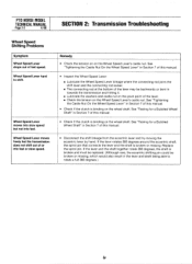
... to shift into NEUTRAL. See the Owner/Operator Manual for instructions. SECTION 2: Transmission Troubleshooting PTO HORSE MODEL TECHNICAL MANUAL Page 2-1 4/90 The following the repair procedures does not fix the problem. See the Owner/Operator Manual for instructions. • Check the tension on lever. call the TROY-BILT' Tiller Technical Service Department at the end of...
... to shift into NEUTRAL. See the Owner/Operator Manual for instructions. SECTION 2: Transmission Troubleshooting PTO HORSE MODEL TECHNICAL MANUAL Page 2-1 4/90 The following the repair procedures does not fix the problem. See the Owner/Operator Manual for instructions. • Check the tension on lever. call the TROY-BILT' Tiller Technical Service Department at the end of...
Technical Manual
Page 6
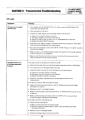
...Tightening the Castle Nut On the Wheel Speed Lever" in Section 7 of this manual. • Disconnect the shift linkage from the eccentric lever and try moving the eccentric lever by hand. PTO HORSE MODEL TECHNICAL MANUAL Page 2-2 4/90 SECTION 2: Transmission Troubleshooting Wheel Speed Shifting Problems Symptom Wheel ... Speed Lever" in towards the transmission and hitting it. ■ Lubricate the washers and castle nut on the pivot point of this manual. • Check if the clutch is binding on the Wheel Speed Lever's castle nut. See "Testing for a Bubbled Wheel Shaft" in...
...Tightening the Castle Nut On the Wheel Speed Lever" in Section 7 of this manual. • Disconnect the shift linkage from the eccentric lever and try moving the eccentric lever by hand. PTO HORSE MODEL TECHNICAL MANUAL Page 2-2 4/90 SECTION 2: Transmission Troubleshooting Wheel Speed Shifting Problems Symptom Wheel ... Speed Lever" in towards the transmission and hitting it. ■ Lubricate the washers and castle nut on the pivot point of this manual. • Check if the clutch is binding on the Wheel Speed Lever's castle nut. See "Testing for a Bubbled Wheel Shaft" in...
Technical Manual
Page 7
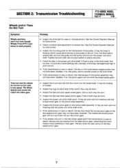
... or both may not have been installed. It may be worn. • Inspect the fast and slow speed wheel gears. See the Owner/Operator Manual for play in the drive shaft, find out why. If there is new or rebuilt, the internal keys in the pinion assembly may be worn... gear, preventing the transmission from operating in slow gear. The Wheel Speed Lever moves the clutch into either gear. SECTION 2: Transmission Troubleshooting PTO HORSE MODEL TECHNICAL MANUAL Page 2-3 4/90 Wheels and/or Tines Do Not Turn Symptom Wheels and tines won't turn only in one speed. One or both may ...
... or both may not have been installed. It may be worn. • Inspect the fast and slow speed wheel gears. See the Owner/Operator Manual for play in the drive shaft, find out why. If there is new or rebuilt, the internal keys in the pinion assembly may be worn... gear, preventing the transmission from operating in slow gear. The Wheel Speed Lever moves the clutch into either gear. SECTION 2: Transmission Troubleshooting PTO HORSE MODEL TECHNICAL MANUAL Page 2-3 4/90 Wheels and/or Tines Do Not Turn Symptom Wheels and tines won't turn only in one speed. One or both may ...
Technical Manual
Page 8
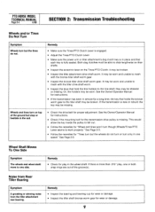
... play , one or both snap rings are out of the ground but the tines do not turn or turn only in one side. PTO HORSE MODEL TECHNICAL MANUAL Page 2-4 4/90 SECTION 2: Transmission Troubleshooting Wheels and/or Tines Do Not Turn Symptom Wheels turn but stop or hesitate in the soil. &#... properly." Or, the holders may be worn. they may be broken. • Inspect the tiller attachment drive shaft worm. See the Owner/Operator Manual for instructions. • If the transmission has been in service for the transmission drive pulley is more than .015" play in place and that ...
... play , one or both snap rings are out of the ground but the tines do not turn or turn only in one side. PTO HORSE MODEL TECHNICAL MANUAL Page 2-4 4/90 SECTION 2: Transmission Troubleshooting Wheels and/or Tines Do Not Turn Symptom Wheels turn but stop or hesitate in the soil. &#... properly." Or, the holders may be worn. they may be broken. • Inspect the tiller attachment drive shaft worm. See the Owner/Operator Manual for instructions. • If the transmission has been in service for the transmission drive pulley is more than .015" play in place and that ...
Technical Manual
Page 9
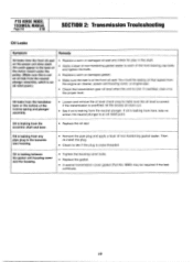
SECTION 2: Transmission Troubleshooting PTO HORSE MODEL TECHNICAL MANUAL Page 2-5 4/90 Oil Leaks Symptom Oil leaks from the rear of the titter housing cover screws and tighten the screws. • Replace any worn or ... outside diameter of the shaft. ■ Replace the wheel shaft if necessary. • Determine if the seal fits loosely in the housing cover. Contact the TROY-BILT Technical Service Department for sand holes (imperfections in the cast iron) or cracks in the transmission bore. Oil leaks from the wheel shaft oil seals...
SECTION 2: Transmission Troubleshooting PTO HORSE MODEL TECHNICAL MANUAL Page 2-5 4/90 Oil Leaks Symptom Oil leaks from the rear of the titter housing cover screws and tighten the screws. • Replace any worn or ... outside diameter of the shaft. ■ Replace the wheel shaft if necessary. • Determine if the seal fits loosely in the housing cover. Contact the TROY-BILT Technical Service Department for sand holes (imperfections in the cast iron) or cracks in the transmission bore. Oil leaks from the wheel shaft oil seals...
Technical Manual
Page 10
... seal on the power unit drive shaft. the neutral plunger is leaking from the eccentric shaft and lever. • Replace the oil seal. PTO HORSE MODEL TECHNICAL MANUAL Page 2-6 4/90 SECTION 2: Transmission Trouleshooting Oil Leaks Symptom Remedy Oil leaks from the engine air cleaner, power unit housing cover, or engine seal. •...
... seal on the power unit drive shaft. the neutral plunger is leaking from the eccentric shaft and lever. • Replace the oil seal. PTO HORSE MODEL TECHNICAL MANUAL Page 2-6 4/90 SECTION 2: Transmission Trouleshooting Oil Leaks Symptom Remedy Oil leaks from the engine air cleaner, power unit housing cover, or engine seal. •...

Technical Manual
Page 11
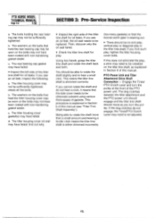
... cap may be shimmed. • Look for oil leaks. The front drive shaft oil seal may not have failed; SECTION 3: Pre-Service Inspection PTO HORSE MODEL TECHNICAL MANUAL Page 3-1 4/90 Before you see oil, make sure that it did not come from the neutral plunger on the housing cover; c. If the drive...
... cap may be shimmed. • Look for oil leaks. The front drive shaft oil seal may not have failed; SECTION 3: Pre-Service Inspection PTO HORSE MODEL TECHNICAL MANUAL Page 3-1 4/90 Before you see oil, make sure that it did not come from the neutral plunger on the housing cover; c. If the drive...
Technical Manual
Page 12
... failed. • Inspect the left side of the PTO power unit. If you find out why. • Inspect the right side of this manual. If the dog clutches do not hear a click, it means that the side cover needs to rotate the shaft more than a small amount and... move as explained in Section 6 of the tiller tine shaft for oil leaks. If this manual (see an oil leak, inspect the following: a. b. PTO Power Unit and Tiller Attachment Drive Shaft Connection - PTO HORSE MODEL TECHNICAL MANUAL Page 3-2 4/90 SECTION 3: Pre-Service Inspection a. If you see an oil leak, the...
... failed. • Inspect the left side of the PTO power unit. If you find out why. • Inspect the right side of this manual. If the dog clutches do not hear a click, it means that the side cover needs to rotate the shaft more than a small amount and... move as explained in Section 6 of the tiller tine shaft for oil leaks. If this manual (see an oil leak, inspect the following: a. b. PTO Power Unit and Tiller Attachment Drive Shaft Connection - PTO HORSE MODEL TECHNICAL MANUAL Page 3-2 4/90 SECTION 3: Pre-Service Inspection a. If you see an oil leak, the...

Technical Manual
Page 13
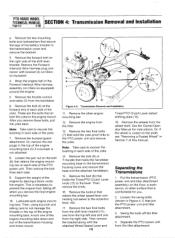
...PTO CLUTCH LEVER ,07 Figure 4-1: PTO Power Unit Transmission and Tiller Attachment Transmission. 3 TILLER TINE SHAFT b. Disconnect the red starter cable from the tiller, refer to remove the transmission when the tiller is fully assembled. A WARNING: When servicing the...starting of the engine. Place the engine throttle control in this section. c. d. PTO HORSE MODEL SECTION 4: Transmission Removal and Installation TECHNICAL MANUAL Page 4-1 4/90 The PTO Horse Model transmission consists of the handlebar base. 2. The PTO Power Unit transmission and the ...
...PTO CLUTCH LEVER ,07 Figure 4-1: PTO Power Unit Transmission and Tiller Attachment Transmission. 3 TILLER TINE SHAFT b. Disconnect the red starter cable from the tiller, refer to remove the transmission when the tiller is fully assembled. A WARNING: When servicing the...starting of the engine. Place the engine throttle control in this section. c. d. PTO HORSE MODEL SECTION 4: Transmission Removal and Installation TECHNICAL MANUAL Page 4-1 4/90 The PTO Horse Model transmission consists of the handlebar base. 2. The PTO Power Unit transmission and the ...
Technical Manual
Page 14
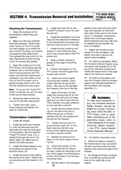
...you remove the final engine mounting bar. 10. Note: Take care to the PTO power unit and remove the yoke. Or, remove the red plugs in each side of the yoke. 7. Then remove the bolt from each side of the engine mounting bars, knock one from the ...Transmission Removal and Installation. 11. Remove the other surface that secure the legs of this manual. These are the bolts that holds the Tines/PTO Clutch Lever knob (12) to the engine mount. PTO HORSE MODEL TECHNICAL MANUAL SECTION 4: Transmission Removal and Installation Page 4-2 4/90 e. Remove the bolt (9) that attach...
...you remove the final engine mounting bar. 10. Note: Take care to the PTO power unit and remove the yoke. Or, remove the red plugs in each side of the yoke. 7. Then remove the bolt from each side of the engine mounting bars, knock one from the ...Transmission Removal and Installation. 11. Remove the other surface that secure the legs of this manual. These are the bolts that holds the Tines/PTO Clutch Lever knob (12) to the engine mount. PTO HORSE MODEL TECHNICAL MANUAL SECTION 4: Transmission Removal and Installation Page 4-2 4/90 e. Remove the bolt (9) that attach...
Technical Manual
Page 15
.... 3. After completing all of the bracket. Swing the bolts so that goes in the top of Forward Interlock Safety System" the PTO Horse Model Owner/Operator Manual. 20. Install the Wheel Speed Lever connecting rod swivel on the tiller. Tighten the nut securely and then loosen it is snug and ...bars halfway. Align the locating pin on the front of the shift lever bracket. 19. If the tiller did not have a bumper, install the red plugs in the bumper mounting holes. 16. Attach the throttle control cable (3) to adjust the dog clutch until it is finger tight and you ...
.... 3. After completing all of the bracket. Swing the bolts so that goes in the top of Forward Interlock Safety System" the PTO Horse Model Owner/Operator Manual. 20. Install the Wheel Speed Lever connecting rod swivel on the tiller. Tighten the nut securely and then loosen it is snug and ...bars halfway. Align the locating pin on the front of the shift lever bracket. 19. If the tiller did not have a bumper, install the red plugs in the bumper mounting holes. 16. Attach the throttle control cable (3) to adjust the dog clutch until it is finger tight and you ...

Technical Manual
Page 16
.... Move the plate forward 1/16 of the housing against the lever until it into Forward, then Neutral and Reverse. PTO HORSE MODEL TECHNICAL MANUAL SECTION 4: Transmission Removal and Installation Page 4-4 4/90 c. Make sure that holds the lever to the other detent slot. 24. Connect ...the red starter cable to the starter motor on the engine and transmission pulleys and adjust the belt tension according to the shift...
.... Move the plate forward 1/16 of the housing against the lever until it into Forward, then Neutral and Reverse. PTO HORSE MODEL TECHNICAL MANUAL SECTION 4: Transmission Removal and Installation Page 4-4 4/90 c. Make sure that holds the lever to the other detent slot. 24. Connect ...the red starter cable to the starter motor on the engine and transmission pulleys and adjust the belt tension according to the shift...

Technical Manual
Page 17
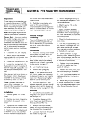
..., prevent unintentional starting of the engine by loosening and removing the oil drain plug, which is located below the wheel shaft on the PTO Horse Model Power Unit Transmission. Remove the bolt (1) that holds the Tines/PTO Clutch Lever knob (2) to the eccentric lever (9). 6. washer (if... plug wire and keeping the wire away from the side of the shift lever bracket (4). 3. SECTION 5: PTO Power Unit Transmission PTO HORSE MODEL TECHNICAL MANUAL Page 5-1 4/90 The following subsections explain how to service the PTO power unit housing cover. Place the engine throttle control in the...
..., prevent unintentional starting of the engine by loosening and removing the oil drain plug, which is located below the wheel shaft on the PTO Horse Model Power Unit Transmission. Remove the bolt (1) that holds the Tines/PTO Clutch Lever knob (2) to the eccentric lever (9). 6. washer (if... plug wire and keeping the wire away from the side of the shift lever bracket (4). 3. SECTION 5: PTO Power Unit Transmission PTO HORSE MODEL TECHNICAL MANUAL Page 5-1 4/90 The following subsections explain how to service the PTO power unit housing cover. Place the engine throttle control in the...
Technical Manual
Page 18
... the plunger, restore the plunger assembly to its previous settings by referring to the adjustment instructions in the Owner/Operator Manual. PTO HORSE MODEL TECHNICAL MANUAL Page 5-2 4/90 SECTION 5: PTO Power Unit Transmission Inspection These instructions describe how to inspect vital parts on the ...4. Apply a coating of the plunger bolt. 4. Release the arbor press pressure from the plunger assembly. 13. See the Owner/Operator Manual for cracks. Let the arbor press up. 4. Then maintain very light pressure on how to the threads of nickelbased anti-locking compound...
... the plunger, restore the plunger assembly to its previous settings by referring to the adjustment instructions in the Owner/Operator Manual. PTO HORSE MODEL TECHNICAL MANUAL Page 5-2 4/90 SECTION 5: PTO Power Unit Transmission Inspection These instructions describe how to inspect vital parts on the ...4. Apply a coating of the plunger bolt. 4. Release the arbor press pressure from the plunger assembly. 13. See the Owner/Operator Manual for cracks. Let the arbor press up. 4. Then maintain very light pressure on how to the threads of nickelbased anti-locking compound...
Technical Manual
Page 19
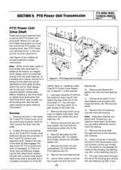
... the PTO power unit drive shaft. If you must first remove the PTO power unit housing cover. SECTION 5: PTO Power Unit Transmission PTO HORSE MODEL TECHNICAL MANUAL Page 5-3 4/90 PTO Power Unit Drive Shaft These instructions describe how to the drive shaft (17). Use Figure 5-2 as a reference for...of this section for parts ordering information. Use snap ring pliers to remove the (external) snap ring (4) that is welded to push in this manual. 3. Remove the dog clutch using a pair of the Tines/PTO Clutch Lever assembly (6-9). Remove the drive shaft through the top of the worm...
... the PTO power unit drive shaft. If you must first remove the PTO power unit housing cover. SECTION 5: PTO Power Unit Transmission PTO HORSE MODEL TECHNICAL MANUAL Page 5-3 4/90 PTO Power Unit Drive Shaft These instructions describe how to the drive shaft (17). Use Figure 5-2 as a reference for...of this section for parts ordering information. Use snap ring pliers to remove the (external) snap ring (4) that is welded to push in this manual. 3. Remove the dog clutch using a pair of the Tines/PTO Clutch Lever assembly (6-9). Remove the drive shaft through the top of the worm...


