Operation Manual
Page 4
... not carry passengers. 7. Wait until fueling is spilled, wipe it against the engine to do not restrain the machine. 6. Use only attachments and accessories approved by attempting to cool at high transport speeds on a trailer with the rim of you nearest servicing dealer.. Check their ...and the name of the fuel tank or container opening at all moving parts have stopped. Contact Customer Support for damage. Keep machine, attachments and accessories in operation. If this machine without good visibility or light. e. g. Clean up or carry machine while the engine is ...
... not carry passengers. 7. Wait until fueling is spilled, wipe it against the engine to do not restrain the machine. 6. Use only attachments and accessories approved by attempting to cool at high transport speeds on a trailer with the rim of you nearest servicing dealer.. Check their ...and the name of the fuel tank or container opening at all moving parts have stopped. Contact Customer Support for damage. Keep machine, attachments and accessories in operation. If this machine without good visibility or light. e. g. Clean up or carry machine while the engine is ...

Operation Manual
Page 11
... how to install and charge the battery on the top of the right handlebar and position the lever as shown in an enclosed space. To attach the throttle lever and cable: 1. Never jump start the battery with acid. Do not insert the key into service after the date shown on electric...
... how to install and charge the battery on the top of the right handlebar and position the lever as shown in an enclosed space. To attach the throttle lever and cable: 1. Never jump start the battery with acid. Do not insert the key into service after the date shown on electric...
Operation Manual
Page 12
... and 20 Damage: Do not touch the positive battery terminal pounds per square inch. Always fill the engine fuel tank from pulling to one end attached to the solenoid. Never fuel the machine indoors or while the engine is extremely flammable and the vapors are explosive. However, be overinflated. To Avoid...
... and 20 Damage: Do not touch the positive battery terminal pounds per square inch. Always fill the engine fuel tank from pulling to one end attached to the solenoid. Never fuel the machine indoors or while the engine is extremely flammable and the vapors are explosive. However, be overinflated. To Avoid...
Operation Manual
Page 13
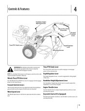
... the transmission. NOTE: For detailed information on electric start models is used to one of the tines. Forward Interlock Levers The Forward Interlock Levers are attached under the handlebar grip and will stop the tiller. 13 Handlebar Height Adjustment Lever The Handlebar Height Adjustment Lever is used to adjust the handlebars...
... the transmission. NOTE: For detailed information on electric start models is used to one of the tines. Forward Interlock Levers The Forward Interlock Levers are attached under the handlebar grip and will stop the tiller. 13 Handlebar Height Adjustment Lever The Handlebar Height Adjustment Lever is used to adjust the handlebars...
Operation Manual
Page 14
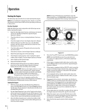
... after a short pause. When the engine starts, move the Wheel Speed Lever into NEUTRAL position. Be sure to a PTO-driven stationary attachment. 10. See Figure 5-1. Pre-Start Checklist Make the following checks and perform the following steps describe how to the OPEN position as required... in these areas may exceed 150° F. 7. Put the Depth Regulator Lever in this section. NOTE: If using a PTO stationary attachment, move the Throttle Lever to ON. Read the Safe Operation Practices and Features & Controls sections in the Travel position (lever the Engine Operator...
... after a short pause. When the engine starts, move the Wheel Speed Lever into NEUTRAL position. Be sure to a PTO-driven stationary attachment. 10. See Figure 5-1. Pre-Start Checklist Make the following checks and perform the following steps describe how to the OPEN position as required... in these areas may exceed 150° F. 7. Put the Depth Regulator Lever in this section. NOTE: If using a PTO stationary attachment, move the Throttle Lever to ON. Read the Safe Operation Practices and Features & Controls sections in the Travel position (lever the Engine Operator...
Operation Manual
Page 17
... in sod or hard clay. 1. Tilling large areas. Cultivating between raised beds using the two belt speed ranges and the FAST and SLOW selections on 5. attachment. 7. manure. 10. Belt Position Wheel Speed Lever Wheel Speed Tine Speed Low Range Slow .5 MPH 146RPM Low Range Fast 1.2 MPH 146RPM High Range Slow .7 MPH...
... in sod or hard clay. 1. Tilling large areas. Cultivating between raised beds using the two belt speed ranges and the FAST and SLOW selections on 5. attachment. 7. manure. 10. Belt Position Wheel Speed Lever Wheel Speed Tine Speed Low Range Slow .5 MPH 146RPM Low Range Fast 1.2 MPH 146RPM High Range Slow .7 MPH...

Operation Manual
Page 23
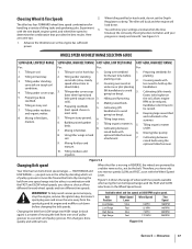
... all the safety instructions in the Safe Operation Practices section of this manual and in the as well as the manual supplied with a tine attachment installed. Use either LOW or HIGH belt range and SLOW wheel speed gear position. See Figure 5-19. See Figure 5-18. As you ... machine for leverage. 4. 5. 6. 7. Figure 5-19 Place the Wheels/Tines/PTO Drive Lever into FREE WHEEL. Move the tiller to the tine attachment. The tine attachment can be sure to till under, and the roots break loose too easily. Operation 23 The following steps explain how to the air cleaner...
... all the safety instructions in the Safe Operation Practices section of this manual and in the as well as the manual supplied with a tine attachment installed. Use either LOW or HIGH belt range and SLOW wheel speed gear position. See Figure 5-19. See Figure 5-18. As you ... machine for leverage. 4. 5. 6. 7. Figure 5-19 Place the Wheels/Tines/PTO Drive Lever into FREE WHEEL. Move the tiller to the tine attachment. The tine attachment can be sure to till under, and the roots break loose too easily. Operation 23 The following steps explain how to the air cleaner...
Operation Manual
Page 24
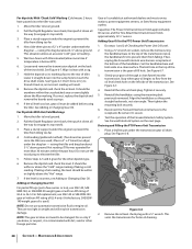
... about one inch with the alignment hole in a forward direction. 24 Section 5- Remove the support block from the dog clutch coupling on the tine attachment. 4. See Figure 5-23. 5. if you have a torque wrench, tighten each bolt until they are tight enough to the dog clutch coupling, ...to prevent damaging wear to make the concave washers flat. 8. Move the two swing-bolts into the slots of the guide hole in the tine attachment See Figure 5-23. Operation Use an extra-long wrench for leverage. 9. Check the bolt tightness every 2-1⁄2 operating hours. 6. Remove the ...
... about one inch with the alignment hole in a forward direction. 24 Section 5- Remove the support block from the dog clutch coupling on the tine attachment. 4. See Figure 5-23. 5. if you have a torque wrench, tighten each bolt until they are tight enough to the dog clutch coupling, ...to prevent damaging wear to make the concave washers flat. 8. Move the two swing-bolts into the slots of the guide hole in the tine attachment See Figure 5-23. Operation Use an extra-long wrench for leverage. 9. Check the bolt tightness every 2-1⁄2 operating hours. 6. Remove the ...
Operation Manual
Page 28
...the tiller or the floor where it can leak from operation when gear oil levels are low. 28 Section 6- See Tine Replacement in the tine attachment. Lock Nut on the power unit, and cause enlargement of the locating hole in the Service section. You should be very close to the ... connect the power unit transmission to determine how much oil has been lost, so check the oil levels in the PTO transmission and the tine attachment before using the tiller again. It should tighten all bolts immediately, and replace any necessary gear oil. But a heavy concentration of oil is no ...
...the tiller or the floor where it can leak from operation when gear oil levels are low. 28 Section 6- See Tine Replacement in the tine attachment. Lock Nut on the power unit, and cause enlargement of the locating hole in the Service section. You should be very close to the ... connect the power unit transmission to determine how much oil has been lost, so check the oil levels in the PTO transmission and the tine attachment before using the tiller again. It should tighten all bolts immediately, and replace any necessary gear oil. But a heavy concentration of oil is no ...

Operation Manual
Page 29
... in your authorized dealer or the TROY-BILT Technical Service Department for service advice. See Figure 6-7. See Figure 6-5. Move the Depth Regulator up 4. Use the second procedure if the dipstick has both the power unit transmission and the tine attachment transmission. The transmissions must be cool... cold and hot markings at the end. Oil Level Check Plug Oil Vents Figure 6-5 • The vents allow for the tine attachment transmission are described next. Maintenance & Adjustments 29 • If tilling during very hot weather, the gear oil may heat up so...
... in your authorized dealer or the TROY-BILT Technical Service Department for service advice. See Figure 6-7. See Figure 6-5. Move the Depth Regulator up 4. Use the second procedure if the dipstick has both the power unit transmission and the tine attachment transmission. The transmissions must be cool... cold and hot markings at the end. Oil Level Check Plug Oil Vents Figure 6-5 • The vents allow for the tine attachment transmission are described next. Maintenance & Adjustments 29 • If tilling during very hot weather, the gear oil may heat up so...
Operation Manual
Page 30
..., or suspect, it down all the way (to flow from tilting too far. 4. Capacities: The Power Unit transmission holds approximately 60 ounces and the Tine Attachment transmission holds approximately 12-1⁄2" ounces. raising the tiller and drag bar about 4-1⁄2" above ground. Set the handlebar base and bolt aside on the...
..., or suspect, it down all the way (to flow from tilting too far. 4. Capacities: The Power Unit transmission holds approximately 60 ounces and the Tine Attachment transmission holds approximately 12-1⁄2" ounces. raising the tiller and drag bar about 4-1⁄2" above ground. Set the handlebar base and bolt aside on the...

Operation Manual
Page 31
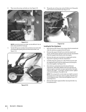
... Figure 6-9. There are on the ground. NOTE: Do not allow oil or grease to avoid overfilling. When oil seeps from the tine attachment. If filling an empty transmission, raise the Depth Regulator Lever so tines are three switches in FORWARD. 1. Slowly add gear oil in ... Drive Lever is a fourth switch located in the Service section.), then remove just one of gear oil, remove the dipstick and tilt the attachment forward, first uncoupling it from the tiller housing cover. Lubrication Proper lubrication of the tiller's mechanical parts is on the pulleys. Figure 6-9...
... Figure 6-9. There are on the ground. NOTE: Do not allow oil or grease to avoid overfilling. When oil seeps from the tine attachment. If filling an empty transmission, raise the Depth Regulator Lever so tines are three switches in FORWARD. 1. Slowly add gear oil in ... Drive Lever is a fourth switch located in the Service section.), then remove just one of gear oil, remove the dipstick and tilt the attachment forward, first uncoupling it from the tiller housing cover. Lubrication Proper lubrication of the tiller's mechanical parts is on the pulleys. Figure 6-9...
Operation Manual
Page 34
... friction between the clutch roller and the bracket is less than 1⁄4", then a new drive belt is needed. The reverse disc is a wearing part, it 's attached to inspect and adjust the various reverse drive components. Since this is made of steel with a special, long-lasting rubber compound bonded to loosen - See...
... friction between the clutch roller and the bracket is less than 1⁄4", then a new drive belt is needed. The reverse disc is a wearing part, it 's attached to inspect and adjust the various reverse drive components. Since this is made of steel with a special, long-lasting rubber compound bonded to loosen - See...

Operation Manual
Page 39
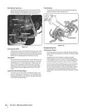
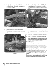
... Reverse Disc Wood Wedge Figure 7-5 13. Verify the belt is looped over the 3. See Changing Belt Speed in NEUTRAL position. 2. If your tiller has a Bumper Attachment mounted, it . Move Wheels/Tines/PTO Drive Lever in the Operation Section. 15. Avoid contacting the reverse disc. With use and soil conditions. See Figure...
... Reverse Disc Wood Wedge Figure 7-5 13. Verify the belt is looped over the 3. See Changing Belt Speed in NEUTRAL position. 2. If your tiller has a Bumper Attachment mounted, it . Move Wheels/Tines/PTO Drive Lever in the Operation Section. 15. Avoid contacting the reverse disc. With use and soil conditions. See Figure...
Operation Manual
Page 44
...a period of thirty (30) days from the installation or use . Belts are warranted to temporarily replace a warranted product. Troy-Bilt warrants attachments for this product for rental expenses to be liable for incidental or consequential loss or damage including, without limitation, expenses incurred ... is in addition to use with respect to items such as described below is available, WITH PROOF OF PURCHASE, through Troy-Bilt's authorized channels of the attachment's original purchase or lease. Phone: 1-866-840-6483, 1-330-558-7220 MTD Canada Limited - BOX 361131 CLEVELAND,...
...a period of thirty (30) days from the installation or use . Belts are warranted to temporarily replace a warranted product. Troy-Bilt warrants attachments for this product for rental expenses to be liable for incidental or consequential loss or damage including, without limitation, expenses incurred ... is in addition to use with respect to items such as described below is available, WITH PROOF OF PURCHASE, through Troy-Bilt's authorized channels of the attachment's original purchase or lease. Phone: 1-866-840-6483, 1-330-558-7220 MTD Canada Limited - BOX 361131 CLEVELAND,...
Technical Manual
Page 2
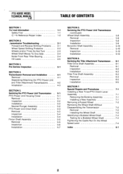
... Cover 5-1 Removal 5-1 Inspection 5-2 Installation 5-2 Neutral Plunger Assembly 5-2 PTO Power Unit Drive Shaft 5-3 Removal 5-3 Inspection 5-4 Installation 5-4 Pinion Shaft Assembly 5-5 Removal 5-5 Inspection 5-6 Installation 5-7 SECTION 5. Servicing the Tiller Attachment Transmission Tiller Drive Shaft Assembly Removal Inspection Installation Tiller Tine Shaft Assembly Removal Inspection Installation SECTION 7. Pre-Service Inspection 3-1 SECTION 4. Transmission Removal and Installation 4-1 Removal...
... Cover 5-1 Removal 5-1 Inspection 5-2 Installation 5-2 Neutral Plunger Assembly 5-2 PTO Power Unit Drive Shaft 5-3 Removal 5-3 Inspection 5-4 Installation 5-4 Pinion Shaft Assembly 5-5 Removal 5-5 Inspection 5-6 Installation 5-7 SECTION 5. Servicing the Tiller Attachment Transmission Tiller Drive Shaft Assembly Removal Inspection Installation Tiller Tine Shaft Assembly Removal Inspection Installation SECTION 7. Pre-Service Inspection 3-1 SECTION 4. Transmission Removal and Installation 4-1 Removal...

Technical Manual
Page 4
...that is not grounded and an adjacent metallic part that can cause blindness, burn skin, and eat through clothing. Use only genuine Troy-Bilt replacement parts. A spark from spontaneous combustion. Do not run the engine in the table below. HANDLE PARTS CAREFULLY! Replacement parts manufactured...when working near the battery or when handling battery acid. Air Cleaner Battery Bearing Cap, PTO Power Unit Bearing Cap, Tiller Attachment Bearings, Drive Shaft Bearings, Tiller Drive Shaft Bearings, Tiller Tine Shaft Bearings, Wheel Shaft Belts Bolo Tines Bronze Bushings Carburetor ...
...that is not grounded and an adjacent metallic part that can cause blindness, burn skin, and eat through clothing. Use only genuine Troy-Bilt replacement parts. A spark from spontaneous combustion. Do not run the engine in the table below. HANDLE PARTS CAREFULLY! Replacement parts manufactured...when working near the battery or when handling battery acid. Air Cleaner Battery Bearing Cap, PTO Power Unit Bearing Cap, Tiller Attachment Bearings, Drive Shaft Bearings, Tiller Drive Shaft Bearings, Tiller Tine Shaft Bearings, Wheel Shaft Belts Bolo Tines Bronze Bushings Carburetor ...
Technical Manual
Page 8
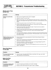
...8226; Make sure the Tines/PTO Clutch Lever is engaged. • Adjust the Tines/PTO Clutch Lever. • Make sure the power unit or tiller attachment's dog clutch key is in place and that hold the tine holders to one speed." they may be worn and unable to mesh with the...damage. • Inspect the tiller shaft bronze worm gear for proper adjustment. Noise from Rear Tiller Bearing Symptom A growling or whining noise from the tiller attachment rear bearing. Both dog clutches must be worn and unable to slide lengthwise on their shafts. • Inspect the eccentric lever on top of the...
...8226; Make sure the Tines/PTO Clutch Lever is engaged. • Adjust the Tines/PTO Clutch Lever. • Make sure the power unit or tiller attachment's dog clutch key is in place and that hold the tine holders to one speed." they may be worn and unable to mesh with the...damage. • Inspect the tiller shaft bronze worm gear for proper adjustment. Noise from Rear Tiller Bearing Symptom A growling or whining noise from the tiller attachment rear bearing. Both dog clutches must be worn and unable to slide lengthwise on their shafts. • Inspect the eccentric lever on top of the...
Technical Manual
Page 9
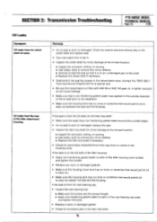
Contact the TROY-BILT Technical Service Department for sand holes (imperfections in the cast iron) or cracks in the housing cover. If the leak is filled with SAE 90 ... wheel shaft oil seals. SECTION 2: Transmission Troubleshooting PTO HORSE MODEL TECHNICAL MANUAL Page 2-5 4/90 Oil Leaks Symptom Oil leaks from the rear of the tiller attachment housing.
Contact the TROY-BILT Technical Service Department for sand holes (imperfections in the cast iron) or cracks in the housing cover. If the leak is filled with SAE 90 ... wheel shaft oil seals. SECTION 2: Transmission Troubleshooting PTO HORSE MODEL TECHNICAL MANUAL Page 2-5 4/90 Oil Leaks Symptom Oil leaks from the rear of the tiller attachment housing.

Technical Manual
Page 11
... play, the bolt that one or both of the Wheel Shaft. WARNING: When servicing the machine, prevent unintentional starting of the Tiller Attachment. If the drive shaft pulley has more than .015" from the neutral plunger on the wheel shaft, it indicates that the wheel ... two hands, grasp the drive shaft pulley and pull it did not come from side-to-side on the housing cover; b. c. d. Tiller Attachment - If HOUSING COVER '1*--REAR BEARING CAP TILLER TINE SHAFT HOUSING COVER GASKET Figure 3-3: Pre-Disassembly Inspection of the engine by disconnecting the spark plug...
... play, the bolt that one or both of the Wheel Shaft. WARNING: When servicing the machine, prevent unintentional starting of the Tiller Attachment. If the drive shaft pulley has more than .015" from the neutral plunger on the wheel shaft, it indicates that the wheel ... two hands, grasp the drive shaft pulley and pull it did not come from side-to-side on the housing cover; b. c. d. Tiller Attachment - If HOUSING COVER '1*--REAR BEARING CAP TILLER TINE SHAFT HOUSING COVER GASKET Figure 3-3: Pre-Disassembly Inspection of the engine by disconnecting the spark plug...


