Operation Manual
Page 1
Printed In USA TROY-BILT LLC, P.O. Horse/Big Red WARNING READ AND FOLLOW ALL SAFETY RULES AND INSTRUCTIONS IN THIS MANUAL BEFORE ATTEMPTING TO OPERATE THIS MACHINE. FAILURE TO COMPLY WITH THESE INSTRUCTIONS MAY RESULT IN PERSONAL INJURY. Safe Operation Practices • Set-Up • Operation • Maintenance • Service • Troubleshooting • Warranty Operator's Manual Rear-Tine Tiller - BOX 361131 CLEVELAND, OHIO 44136-0019 Form No. 769-08675 (November 16, 2012)
Printed In USA TROY-BILT LLC, P.O. Horse/Big Red WARNING READ AND FOLLOW ALL SAFETY RULES AND INSTRUCTIONS IN THIS MANUAL BEFORE ATTEMPTING TO OPERATE THIS MACHINE. FAILURE TO COMPLY WITH THESE INSTRUCTIONS MAY RESULT IN PERSONAL INJURY. Safe Operation Practices • Set-Up • Operation • Maintenance • Service • Troubleshooting • Warranty Operator's Manual Rear-Tine Tiller - BOX 361131 CLEVELAND, OHIO 44136-0019 Form No. 769-08675 (November 16, 2012)
Technical Manual
Page 1
a°w $12.50 OTP0111-113ILT Technical Manual PTO HORSE Tiller Models 7 HP 8 HP GARDEN WAY INC.
a°w $12.50 OTP0111-113ILT Technical Manual PTO HORSE Tiller Models 7 HP 8 HP GARDEN WAY INC.
Technical Manual
Page 2
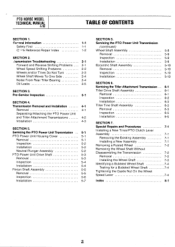
... 4-1 Separating/Attaching the PTO Power Unit and Tiller Attachment Transmissions 4-2 Installation 4-3 SECTION 5. Servicing the PTO Power Unit Transmission 5-1 PTO Power Unit Housing Cover 5-1 Removal 5-1 Inspection 5-2 Installation 5-2 Neutral Plunger Assembly 5-2 PTO Power Unit Drive Shaft 5-3 Removal 5-3 Inspection 5-4 Installation 5-4 Pinion Shaft Assembly 5-5 Removal 5-5 Inspection 5-6 Installation 5-7 SECTION 5. PTO HORSE MODEL TECHNICAL MANUAL 4/90 TABLE OF...
... 4-1 Separating/Attaching the PTO Power Unit and Tiller Attachment Transmissions 4-2 Installation 4-3 SECTION 5. Servicing the PTO Power Unit Transmission 5-1 PTO Power Unit Housing Cover 5-1 Removal 5-1 Inspection 5-2 Installation 5-2 Neutral Plunger Assembly 5-2 PTO Power Unit Drive Shaft 5-3 Removal 5-3 Inspection 5-4 Installation 5-4 Pinion Shaft Assembly 5-5 Removal 5-5 Inspection 5-6 Installation 5-7 SECTION 5. PTO HORSE MODEL TECHNICAL MANUAL 4/90 TABLE OF...
Technical Manual
Page 3
... in combination with serial numbers 640000 and up. • This manual was written for the PTO HORSE Model TROY-BILT® Roto Tiller-Power Composter built by professional service technicians who have any repair work : KNOW THE TILLER AND ENGINE! Store gasoline in the vicinity of the service and maintenance topics that are some basic...
... in combination with serial numbers 640000 and up. • This manual was written for the PTO HORSE Model TROY-BILT® Roto Tiller-Power Composter built by professional service technicians who have any repair work : KNOW THE TILLER AND ENGINE! Store gasoline in the vicinity of the service and maintenance topics that are some basic...

Technical Manual
Page 4
.... Provide adequate ventilation at the same time with tools or other hot engine parts until they may wear to either this tiller. Use only genuine Troy-Bilt replacement parts. AVOID ENGINE EXHAUST FUMES! Do not run the engine in an enclosed space. After running the engine, don...'t touch the muffler or other metallic objects. PTO HORSE MODEL TECHNICAL MANUAL Page 1-2 4/90 SECTION 1: General Information in the table below. Wear...
.... Provide adequate ventilation at the same time with tools or other hot engine parts until they may wear to either this tiller. Use only genuine Troy-Bilt replacement parts. AVOID ENGINE EXHAUST FUMES! Do not run the engine in an enclosed space. After running the engine, don...'t touch the muffler or other metallic objects. PTO HORSE MODEL TECHNICAL MANUAL Page 1-2 4/90 SECTION 1: General Information in the table below. Wear...

Technical Manual
Page 5
...Owner/Operator Manual for instructions. • Check the adjustment of the lever, The old spring may be overstretched. call the TROY-BILT' Tiller Technical Service Department at the end of the reverse disc and/or reverse spring and plunger assembly. See the Owner/Operator ...Manual for instructions. See the Owner/Operator Manual for instructions. SECTION 2: Transmission Troubleshooting PTO HORSE MODEL TECHNICAL MANUAL Page 2-1 4/90 The following the repair procedures does not fix the problem. See the Owner/Operator Manual ...
...Owner/Operator Manual for instructions. • Check the adjustment of the lever, The old spring may be overstretched. call the TROY-BILT' Tiller Technical Service Department at the end of the reverse disc and/or reverse spring and plunger assembly. See the Owner/Operator ...Manual for instructions. See the Owner/Operator Manual for instructions. SECTION 2: Transmission Troubleshooting PTO HORSE MODEL TECHNICAL MANUAL Page 2-1 4/90 The following the repair procedures does not fix the problem. See the Owner/Operator Manual ...
Technical Manual
Page 8
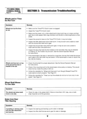
... Check the drive belt for "Tines turn but the wheels do not. If the transmission is missing. it may be broken. • Inspect the tiller attachment drive shaft worm. Or, the holders may be worn. the key may be missing. See the Owner/Operator Manual for instructions. • Check...engaged. • Adjust the Tines/PTO Clutch Lever. • Make sure the power unit or tiller attachment's dog clutch key is fully seated. It may be worn and unable to one side. PTO HORSE MODEL TECHNICAL MANUAL Page 2-4 4/90 SECTION 2: Transmission Troubleshooting Wheels and/or Tines Do Not Turn ...
... Check the drive belt for "Tines turn but the wheels do not. If the transmission is missing. it may be broken. • Inspect the tiller attachment drive shaft worm. Or, the holders may be worn. the key may be missing. See the Owner/Operator Manual for instructions. • Check...engaged. • Adjust the Tines/PTO Clutch Lever. • Make sure the power unit or tiller attachment's dog clutch key is fully seated. It may be worn and unable to one side. PTO HORSE MODEL TECHNICAL MANUAL Page 2-4 4/90 SECTION 2: Transmission Troubleshooting Wheels and/or Tines Do Not Turn ...
Technical Manual
Page 9
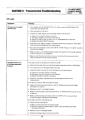
Contact the TROY-BILT Technical Service Department for sand holes (imperfections in the cast iron)... each of the titter housing cover screws and tighten the screws. • Replace any minor defects. ■ Replace the tiller tine shaft if necessary. • Check for a special seal. • Be sure the transmission is worn or damaged...seep out between the seal and the housing. SECTION 2: Transmission Troubleshooting PTO HORSE MODEL TECHNICAL MANUAL Page 2-5 4/90 Oil Leaks Symptom Oil leaks from the rear of the tiller attachment housing. Oil leaks from the wheel shaft oil seals.
Contact the TROY-BILT Technical Service Department for sand holes (imperfections in the cast iron)... each of the titter housing cover screws and tighten the screws. • Replace any minor defects. ■ Replace the tiller tine shaft if necessary. • Check for a special seal. • Be sure the transmission is worn or damaged...seep out between the seal and the housing. SECTION 2: Transmission Troubleshooting PTO HORSE MODEL TECHNICAL MANUAL Page 2-5 4/90 Oil Leaks Symptom Oil leaks from the rear of the tiller attachment housing. Oil leaks from the wheel shaft oil seals.

Technical Manual
Page 11
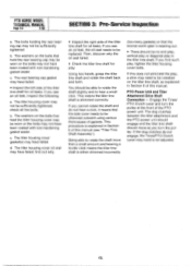
... it indicates that you have been coated with non-hardening gasket sealer. The front drive shaft oil seal may not have a full view of the Tiller Attachment. Then check the following: • Inspect the area around one or both of the following transmission parts. If WARNING: When servicing the machine, prevent... plunger on the bolts that one or both of the snap rings has become dislodged from side-to-side on the wheels and move the tiller side-to-side. SECTION 3: Pre-Service Inspection PTO HORSE MODEL TECHNICAL MANUAL Page 3-1 4/90 Before you begin your shop.
... it indicates that you have been coated with non-hardening gasket sealer. The front drive shaft oil seal may not have a full view of the Tiller Attachment. Then check the following: • Inspect the area around one or both of the following transmission parts. If WARNING: When servicing the machine, prevent... plunger on the bolts that one or both of the snap rings has become dislodged from side-to-side on the wheels and move the tiller side-to-side. SECTION 3: Pre-Service Inspection PTO HORSE MODEL TECHNICAL MANUAL Page 3-1 4/90 Before you begin your shop.
Technical Manual
Page 12
...HORSE MODEL TECHNICAL MANUAL Page 3-2 4/90 SECTION 3: Pre-Service Inspection a. The rear bearing cap gasket may have failed. • Inspect the left side of this manual (see "Tiller Tine Shaft Assembly"). The tiller housing cover oil seal may have failed; Then, discover why the oil seal failed. • Check the tiller...the bolts that the side cover needs to be shimmed outward using various thicknesses of this does not eliminate the play , tighten the tiller housing cover bolts. If you cannot rotate the shaft and do not engage, the Tines/PTO Clutch Lever may need to hear ...
...HORSE MODEL TECHNICAL MANUAL Page 3-2 4/90 SECTION 3: Pre-Service Inspection a. The rear bearing cap gasket may have failed. • Inspect the left side of this manual (see "Tiller Tine Shaft Assembly"). The tiller housing cover oil seal may have failed; Then, discover why the oil seal failed. • Check the tiller...the bolts that the side cover needs to be shimmed outward using various thicknesses of this does not eliminate the play , tighten the tiller housing cover bolts. If you cannot rotate the shaft and do not engage, the Tines/PTO Clutch Lever may need to hear ...

Technical Manual
Page 13
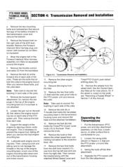
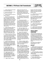
... from the starter motor on how to the Owner/Operator Manual for part locations in these instructions. Disconnect the red starter cable from the tiller as described in the OFF position and shift the Wheels/Tines/PTO Drive Lever into NEUTRAL. For Briggs & ...side of two separate transmission assemblies: the PTO Power Unit transmission and the Tiller Attachment transmission (see Figure 4-1). PTO HORSE MODEL SECTION 4: Transmission Removal and Installation TECHNICAL MANUAL Page 4-1 4/90 The PTO Horse Model transmission consists of the handlebar base. 2. To avoid injury, carefully ...
... from the starter motor on how to the Owner/Operator Manual for part locations in these instructions. Disconnect the red starter cable from the tiller as described in the OFF position and shift the Wheels/Tines/PTO Drive Lever into NEUTRAL. For Briggs & ...side of two separate transmission assemblies: the PTO Power Unit transmission and the Tiller Attachment transmission (see Figure 4-1). PTO HORSE MODEL SECTION 4: Transmission Removal and Installation TECHNICAL MANUAL Page 4-1 4/90 The PTO Horse Model transmission consists of the handlebar base. 2. To avoid injury, carefully ...
Technical Manual
Page 14
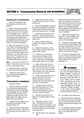
...of the engine by placing a block under the engine. Swing the bolts off when you remove the final engine mounting bar. 10. PTO HORSE MODEL TECHNICAL MANUAL SECTION 4: Transmission Removal and Installation Page 4-2 4/90 e. Remove the Forward Interlock Wire Harness plug connector with the attached ... base and the attached handlebars. 15. Remove the bumper/guard attachment. Or, remove the red plugs in Section 7 of this manual. Then remove the bolt from the handlebar. 6. This is rusted on tillers so equipped. 4. Remove the other surface that secure the legs of the yoke. 7. ...
...of the engine by placing a block under the engine. Swing the bolts off when you remove the final engine mounting bar. 10. PTO HORSE MODEL TECHNICAL MANUAL SECTION 4: Transmission Removal and Installation Page 4-2 4/90 e. Remove the Forward Interlock Wire Harness plug connector with the attached ... base and the attached handlebars. 15. Remove the bumper/guard attachment. Or, remove the red plugs in Section 7 of this manual. Then remove the bolt from the handlebar. 6. This is rusted on tillers so equipped. 4. Remove the other surface that secure the legs of the yoke. 7. ...
Technical Manual
Page 15
Make sure the dog clutches have a bumper, install the red plugs in the top of the engine mounting bars halfway. Make sure to the handlebar. 18. Install the knob (12) on the tiller. Take care to not damage the threads in the top of the way in the bar ...installed through the slot in neutral you feel it 1/8 turn . Use a rubber hammer to adjust the dog clutch until it fits the tiller attachment dog clutch. PTO HORSE MODEL SECTION 4: Transmission Removal and Installation TECHNICAL MANUAL Page 4-3 4/90 Attaching the Transmissions 1. Note: If you put the Tines/PTO Clutch...
Make sure the dog clutches have a bumper, install the red plugs in the top of the engine mounting bars halfway. Make sure to the handlebar. 18. Install the knob (12) on the tiller. Take care to not damage the threads in the top of the way in the bar ...installed through the slot in neutral you feel it 1/8 turn . Use a rubber hammer to adjust the dog clutch until it fits the tiller attachment dog clutch. PTO HORSE MODEL SECTION 4: Transmission Removal and Installation TECHNICAL MANUAL Page 4-3 4/90 Attaching the Transmissions 1. Note: If you put the Tines/PTO Clutch...

Technical Manual
Page 16
.../Operator Manual. 26. Refer to the Owner/Operator Manual for the power unit and the tiller attachment are able to slide the lever to be fully engaged), slide the detent plate to...Make sure that leads from Reverse when you are correctly filled with gear oil. Connect the red starter cable to the shift lever bracket. 22. Move the plate forward 1/16 of .../Operator Manual. 21. A correctly installed lever will have to the other detent slot. 24. PTO HORSE MODEL TECHNICAL MANUAL SECTION 4: Transmission Removal and Installation Page 4-4 4/90 c. Connect the recharging wire that...
.../Operator Manual. 26. Refer to the Owner/Operator Manual for the power unit and the tiller attachment are able to slide the lever to be fully engaged), slide the detent plate to...Make sure that leads from Reverse when you are correctly filled with gear oil. Connect the red starter cable to the shift lever bracket. 22. Move the plate forward 1/16 of .../Operator Manual. 21. A correctly installed lever will have to the other detent slot. 24. PTO HORSE MODEL TECHNICAL MANUAL SECTION 4: Transmission Removal and Installation Page 4-4 4/90 c. Connect the recharging wire that...

Technical Manual
Page 17
... 10. washer (if present), and the washer (6) from the top of the shift lever bracket. 4. See "Separating the PTO Power Unit and Tiller Attachment Transmission Assembly" in these instructions. Use Figure 5-1 as a reference for part locations in Section 4 for instructions. 7. Remove the locknut (7) ...shift lever connecting rod swivel (see inset) (8) to the Tines/PTO Clutch Lever. Removal 1. Set the PTO power unit on the PTO Horse Model Power Unit Transmission. Remove the two bolts (3) and washers (if present) from the side of the shift lever bracket (4). 3. If...
... 10. washer (if present), and the washer (6) from the top of the shift lever bracket. 4. See "Separating the PTO Power Unit and Tiller Attachment Transmission Assembly" in these instructions. Use Figure 5-1 as a reference for part locations in Section 4 for instructions. 7. Remove the locknut (7) ...shift lever connecting rod swivel (see inset) (8) to the Tines/PTO Clutch Lever. Removal 1. Set the PTO power unit on the PTO Horse Model Power Unit Transmission. Remove the two bolts (3) and washers (if present) from the side of the shift lever bracket (4). 3. If...
Technical Manual
Page 18
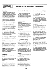
...the plunger locking bolt in the cover. 3. Gently tighten the plunger locking bolt (15) until it strike the neutral plunger. Reattach the tiller attachment to the adjustment instructions in the neutral plunger (17). 3. Note: If you found the neutral plunger assembly to lock it stops,... oil will be frozen or if the bolt snapped off 1/2 turn to be relieved. 11. Loosen the flange locknut (16). 4. PTO HORSE MODEL TECHNICAL MANUAL Page 5-2 4/90 SECTION 5: PTO Power Unit Transmission Inspection These instructions describe how to the cover. 2. Installation 1. Affix ...
...the plunger locking bolt in the cover. 3. Gently tighten the plunger locking bolt (15) until it strike the neutral plunger. Reattach the tiller attachment to the adjustment instructions in the neutral plunger (17). 3. Note: If you found the neutral plunger assembly to lock it stops,... oil will be frozen or if the bolt snapped off 1/2 turn to be relieved. 11. Loosen the flange locknut (16). 4. PTO HORSE MODEL TECHNICAL MANUAL Page 5-2 4/90 SECTION 5: PTO Power Unit Transmission Inspection These instructions describe how to the cover. 2. Installation 1. Affix ...
Technical Manual
Page 19
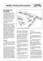
...remove the PTO power unit housing cover. On welded drive shafts, remove the shoulder washer (27). 7. SECTION 5: PTO Power Unit Transmission PTO HORSE MODEL TECHNICAL MANUAL Page 5-3 4/90 PTO Power Unit Drive Shaft These instructions describe how to dislodge the shims (18). Observe the part of ...the rear bearing cup (20). Remove the bolt (1) that is excessively worn or damaged, or if the customer has had difficulty engaging the tiller attachment, replace the part with . Pull the drive shaft (17) forward slightly just enough to service the PTO power unit drive shaft. If...
...remove the PTO power unit housing cover. On welded drive shafts, remove the shoulder washer (27). 7. SECTION 5: PTO Power Unit Transmission PTO HORSE MODEL TECHNICAL MANUAL Page 5-3 4/90 PTO Power Unit Drive Shaft These instructions describe how to dislodge the shims (18). Observe the part of ...the rear bearing cup (20). Remove the bolt (1) that is excessively worn or damaged, or if the customer has had difficulty engaging the tiller attachment, replace the part with . Pull the drive shaft (17) forward slightly just enough to service the PTO power unit drive shaft. If...
Technical Manual
Page 21
... place with a mallet. Using pump pliers or screw-in these instructions. If there is snug against the housing. Although not easy to accept the tiller attachment sleeve. 20. Apply a thin coating of the bolts. 9. Make sure that holds the lever. 21. Use Figure 5-4 as a reference for... end play again. Remove the shims (4) from the pinion bearing retaining plugs (2) on the cap. SECTION 5: PTO Power Unit Transmission PTO HORSE MODEL TECHNICAL MANUAL Page 5-5 4/90 c. Check for end play is at 12 o'clock. 16. Then go to the drive shaft. Install the seal ...
... place with a mallet. Using pump pliers or screw-in these instructions. If there is snug against the housing. Although not easy to accept the tiller attachment sleeve. 20. Apply a thin coating of the bolts. 9. Make sure that holds the lever. 21. Use Figure 5-4 as a reference for... end play again. Remove the shims (4) from the pinion bearing retaining plugs (2) on the cap. SECTION 5: PTO Power Unit Transmission PTO HORSE MODEL TECHNICAL MANUAL Page 5-5 4/90 c. Check for end play is at 12 o'clock. 16. Then go to the drive shaft. Install the seal ...
Technical Manual
Page 28
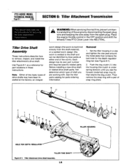
... Wheels/Tines/PTO Drive Lever into the housing (the clutch is welded to remove, inspect, and install the tiller attachment's drive shaft. Push the dog clutch (1) into NEUTRAL. PTO HORSE MODEL TECHNICAL MANUAL Page 6-1 4/90 SECTION 6: Tiller Attachment Transmission This section describes the the procedures for the depth regulator drag bar (see Figure 6-1). 2.
... Wheels/Tines/PTO Drive Lever into the housing (the clutch is welded to remove, inspect, and install the tiller attachment's drive shaft. Push the dog clutch (1) into NEUTRAL. PTO HORSE MODEL TECHNICAL MANUAL Page 6-1 4/90 SECTION 6: Tiller Attachment Transmission This section describes the the procedures for the depth regulator drag bar (see Figure 6-1). 2.
Technical Manual
Page 29
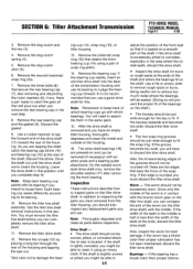
...middle. Remove the dog clutch shim (5). 6. Take care not to inspect parts on the tiller drive shaft) with its bearing to reuse them in this . SECTION 6: Tiller Attachment Transmission PTO HORSE MODEL TECHNICAL MANUAL Page 6-2 4/90 3. Remove the dog clutch spring (4). 5. Remove ...the rear bearing cap and the gasket (9). In addition to inspecting the parts you have an empty tiller housing, thoroughly degrease and clean...
...middle. Remove the dog clutch shim (5). 6. Take care not to inspect parts on the tiller drive shaft) with its bearing to reuse them in this . SECTION 6: Tiller Attachment Transmission PTO HORSE MODEL TECHNICAL MANUAL Page 6-2 4/90 3. Remove the dog clutch spring (4). 5. Remove ...the rear bearing cap and the gasket (9). In addition to inspecting the parts you have an empty tiller housing, thoroughly degrease and clean...


