
Users Manual Canada; English
Page 3
... Optional devices 3-15 Bridge media slot 3-20 Optional accessories 3-37 Chapter 4 Operating Basics TOSHIBA Dual Pointing Device 4-1 Using the Fingerprint Sensor 4-3 Web Camera 4-10 Using the TOSHIBA Face Recognition 4-11 Using optical disc drives 4-14 Writing CD/DVDs on DVD Super Multi drives 4-18 Media care 4-24 Sound System 4-25 Modem 4-28 Wireless communications 4-31 LAN 4-34 Computer Handling 4-36 Using the Hard Disk Drive (HDD) Protection 4-37 Using the TOSHIBA USB Sleep and Charge Utility 4-39 Heat dispersal 4-41 Chapter 5 The Keyboard Typewriter keys 5-1 Function...
... Optional devices 3-15 Bridge media slot 3-20 Optional accessories 3-37 Chapter 4 Operating Basics TOSHIBA Dual Pointing Device 4-1 Using the Fingerprint Sensor 4-3 Web Camera 4-10 Using the TOSHIBA Face Recognition 4-11 Using optical disc drives 4-14 Writing CD/DVDs on DVD Super Multi drives 4-18 Media care 4-24 Sound System 4-25 Modem 4-28 Wireless communications 4-31 LAN 4-34 Computer Handling 4-36 Using the Hard Disk Drive (HDD) Protection 4-37 Using the TOSHIBA USB Sleep and Charge Utility 4-39 Heat dispersal 4-41 Chapter 5 The Keyboard Typewriter keys 5-1 Function...

Users Manual Canada; English
Page 4
...*1 G-1 CPU*2 G-1 Memory (Main System)*3 G-2 Battery Life*4 G-3 Hard Disk Drive (HDD) Capacity*5 G-3 User's Manual iv TECRA A11/S11/P11/Satellite Pro S500 Chapter 6 Power and Power-Up Modes Power conditions 6-1 Monitoring of power condition 6-2 Battery 6-3 TOSHIBA Password Utility 6-10 Power-up modes 6-12 Panel power on/off 6-12 System automatic Sleep/Hibernation 6-13 Chapter 7 HW Setup Accessing HW Setup 7-1 HW Setup window 7-1 Chapter 8 Troubleshooting Problem solving process 8-1 Hardware and system checklist 8-3 TOSHIBA support 8-26 Appendix A Specifications Physical...
...*1 G-1 CPU*2 G-1 Memory (Main System)*3 G-2 Battery Life*4 G-3 Hard Disk Drive (HDD) Capacity*5 G-3 User's Manual iv TECRA A11/S11/P11/Satellite Pro S500 Chapter 6 Power and Power-Up Modes Power conditions 6-1 Monitoring of power condition 6-2 Battery 6-3 TOSHIBA Password Utility 6-10 Power-up modes 6-12 Panel power on/off 6-12 System automatic Sleep/Hibernation 6-13 Chapter 7 HW Setup Accessing HW Setup 7-1 HW Setup window 7-1 Chapter 8 Troubleshooting Problem solving process 8-1 Hardware and system checklist 8-3 TOSHIBA support 8-26 Appendix A Specifications Physical...

Users Manual Canada; English
Page 6
... use beyond that stipulated above (including conversion to digital format, alteration, transfer of MultiMediaCard Association. Memory Stick, Memory Stick PRO, Memory Stick PRO Duo and i.LINK are trademarks of Sony Corporation. Secure Digital and SD are trademarks or registered trademarks of SD Card Association. TOSHIBA TECRA A11/S11/P11/Satellite Pro S500 Portable Personal Computer User's Manual First edition January 2010 Copyright authority for the TOSHIBA TECRA...
... use beyond that stipulated above (including conversion to digital format, alteration, transfer of MultiMediaCard Association. Memory Stick, Memory Stick PRO, Memory Stick PRO Duo and i.LINK are trademarks of Sony Corporation. Secure Digital and SD are trademarks or registered trademarks of SD Card Association. TOSHIBA TECRA A11/S11/P11/Satellite Pro S500 Portable Personal Computer User's Manual First edition January 2010 Copyright authority for the TOSHIBA TECRA...

Users Manual Canada; English
Page 11
TECRA A11/S11/P11/Satellite Pro S500 Pursuant to FCC CFR 47, Part 68: When you are ready to install or use the modem, call the telephone company and let them to make changes in writing to allow you are ever needed on standard-device telephone lines. For the REN of the modem, which is to be installed, or, if already installed, on the...
TECRA A11/S11/P11/Satellite Pro S500 Pursuant to FCC CFR 47, Part 68: When you are ready to install or use the modem, call the telephone company and let them to make changes in writing to allow you are ever needed on standard-device telephone lines. For the REN of the modem, which is to be installed, or, if already installed, on the...

Users Manual Canada; English
Page 24
... in Chapter 3, Hardware, Utilities and Options to learn how this manual by -step instructions on Chapter 7, HW Setup, to understand how to describe, identify, and highlight terms and operating procedures. Then read the Special features section in the Glossary. User's Manual xxii For example: Read Only Memory (ROM). Acronyms are enclosed in parentheses following formats to setup and configure these features. This powerful notebook computer provides...
... in Chapter 3, Hardware, Utilities and Options to learn how this manual by -step instructions on Chapter 7, HW Setup, to understand how to describe, identify, and highlight terms and operating procedures. Then read the Special features section in the Glossary. User's Manual xxii For example: Read Only Memory (ROM). Acronyms are enclosed in parentheses following formats to setup and configure these features. This powerful notebook computer provides...
Users Manual Canada; English
Page 38
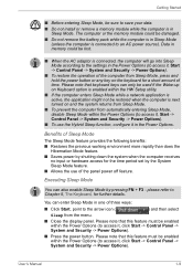
... hardware access for the time period set by pressing FN + F3 - You can enter Sleep Mode in the Power Options (to an AC power source). Please note that keyboard keys can also enable Sleep Mode by the System Sleep Mode feature. ■ Allows the use of three ways: ■ Click Start, point to access it, Start -> Control Panel -> System and Security -> Power Options). ■ To use the Hybrid Sleep function, configure it , Start -> Control Panel -> System and Security -> Power Options). ■ To restore the operation...
... hardware access for the time period set by pressing FN + F3 - You can enter Sleep Mode in the Power Options (to an AC power source). Please note that keyboard keys can also enable Sleep Mode by the System Sleep Mode feature. ■ Allows the use of three ways: ■ Click Start, point to access it, Start -> Control Panel -> System and Security -> Power Options). ■ To use the Hybrid Sleep function, configure it , Start -> Control Panel -> System and Security -> Power Options). ■ To restore the operation...
Users Manual Canada; English
Page 46
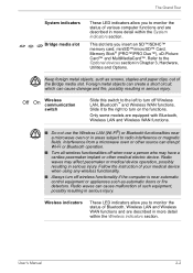
... System indicators section. This slot lets you insert an SD™/SDHC™ memory card, miniSD™/microSD™ Card, Memory Stick® (PRO™/PRO Duo™), xD-Picture Card™ and MultiMediaCard™. Foreign metal objects can create a short circuit, which can cause malfunction of your medical device when using any wireless functionality. ■ Always turn off Wireless LAN, Bluetooth™ and Wireless WAN functions. Follow the instruction of...
... System indicators section. This slot lets you insert an SD™/SDHC™ memory card, miniSD™/microSD™ Card, Memory Stick® (PRO™/PRO Duo™), xD-Picture Card™ and MultiMediaCard™. Foreign metal objects can create a short circuit, which can cause malfunction of your medical device when using any wireless functionality. ■ Always turn off Wireless LAN, Bluetooth™ and Wireless WAN functions. Follow the instruction of...
Users Manual Canada; English
Page 50
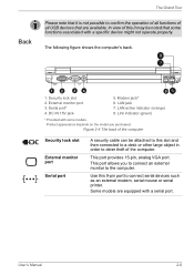
... an external modem, serial mouse or serial printer. External monitor port 3. LAN jack 7. This port provides 15-pin, analog VGA port. This port allows you purchased. LAN active indicator (orange) 8. Serial port* 4. Figure 2-4 The back of this it is not possible to confirm the operation of all functions of all USB devices that some models. In view of the computer Security lock slot External monitor port Serial port A security cable can be noted that are equipped with some functions associated with a specific device...
... an external modem, serial mouse or serial printer. External monitor port 3. LAN jack 7. This port provides 15-pin, analog VGA port. This port allows you purchased. LAN active indicator (orange) 8. Serial port* 4. Figure 2-4 The back of this it is not possible to confirm the operation of all functions of all USB devices that some models. In view of the computer Security lock slot External monitor port Serial port A security cable can be noted that are equipped with some functions associated with a specific device...
Users Manual Canada; English
Page 66
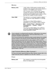
... the computer. The actual amount of 8,192MB. The amount of Video RAM available is configured with memory modules of a maximum size of useable system memory will still be approximately 3 GB only. If your computer, the memory available to the operating system. Hardware, Utilities and Options Memory Memory slots Video RAM 1 GB, 2 GB or 4 GB memory modules can be installed in Appendix G or click the *3 above. Start -> Control Panel -> Appearance and Personalization -> Display -> Adjust resolution.
... the computer. The actual amount of 8,192MB. The amount of Video RAM available is configured with memory modules of a maximum size of useable system memory will still be approximately 3 GB only. If your computer, the memory available to the operating system. Hardware, Utilities and Options Memory Memory slots Video RAM 1 GB, 2 GB or 4 GB memory modules can be installed in Appendix G or click the *3 above. Start -> Control Panel -> Appearance and Personalization -> Display -> Adjust resolution.
Users Manual Canada; English
Page 88
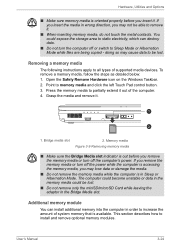
... order to be lost . doing so may cause data to increase the amount of supported media devices. Grasp the media and remove it . User's Manual 3-24 You could be lost . ■ Do not remove only the miniSD/microSD Card while leaving the adaptor in the Bridge Media slot. Point to install and remove optional memory modules. This section describes how to memory media and click the left Touch Pad control button. 3. Hardware, Utilities and Options ■ Make...
... order to be lost . doing so may cause data to increase the amount of supported media devices. Grasp the media and remove it . User's Manual 3-24 You could be lost . ■ Do not remove only the miniSD/microSD Card while leaving the adaptor in the Bridge Media slot. Point to install and remove optional memory modules. This section describes how to memory media and click the left Touch Pad control button. 3. Hardware, Utilities and Options ■ Make...
Users Manual Canada; English
Page 92
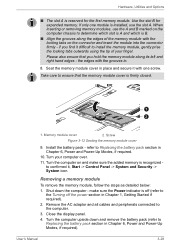
... Started if required). 2. Memory module cover 2. refer to install the memory module, gently prise the locking tabs outwards using the tip of the memory module with the grooves in Chapter 6, Power and Power-Up Modes, if required. 10. Turn the computer on and make sure the Power indicator is off the power section in Chapter 6, Power and Power-Up Modes, if required). Close the display panel. 4. When inserting or removing memory modules, use the slot A. if you hold the memory module...
... Started if required). 2. Memory module cover 2. refer to install the memory module, gently prise the locking tabs outwards using the tip of the memory module with the grooves in Chapter 6, Power and Power-Up Modes, if required. 10. Turn the computer on and make sure the Power indicator is off the power section in Chapter 6, Power and Power-Up Modes, if required). Close the display panel. 4. When inserting or removing memory modules, use the slot A. if you hold the memory module...
Users Manual Canada; English
Page 99
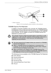
... with TOSHIBA Express Port Replicator. Logging onto a LAN using the computer's default settings could cause a malfunction in LAN operation. Do not use the following ports are available on the underside of ports. Hardware, Utilities and Options 2 1 1. The TOSHIBA Express Port Replicator connects directly to the docking interface on the TOSHIBA Express Port Replicator. ■ RJ45 LAN jack ■ External monitor port ■ DC IN 15V jack ■ Security lock slot ■ Universal Serial Bus 2.0 port (four) ■ DVI port User's Manual 3-35...
... with TOSHIBA Express Port Replicator. Logging onto a LAN using the computer's default settings could cause a malfunction in LAN operation. Do not use the following ports are available on the underside of ports. Hardware, Utilities and Options 2 1 1. The TOSHIBA Express Port Replicator connects directly to the docking interface on the TOSHIBA Express Port Replicator. ■ RJ45 LAN jack ■ External monitor port ■ DC IN 15V jack ■ Security lock slot ■ Universal Serial Bus 2.0 port (four) ■ DVI port User's Manual 3-35...
Users Manual Canada; English
Page 171
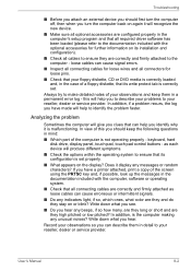
... noises? Record your observations so you hear. keyboard, hard disk drive, display panel, touch pad, touch pad control buttons - loose cables can describe them in the case of the screen using the PRTSC key and, if possible, look up the messages in the documentation included with the optional accessories for loose pins. ■ Check that its write protect tab is correctly set properly. ■ What appears on the display? User's Manual 8-2
... noises? Record your observations so you hear. keyboard, hard disk drive, display panel, touch pad, touch pad control buttons - loose cables can describe them in the case of the screen using the PRTSC key and, if possible, look up the messages in the documentation included with the optional accessories for loose pins. ■ Check that its write protect tab is correctly set properly. ■ What appears on the display? User's Manual 8-2

Users Manual Canada; English
Page 176
... not remapping the keyboard in the BIOS setup application by the setup and configuration of each key). Release the F2 key when the TOSHIBA Leading Innovation >>> screen appears - Problem Some letter keys produce numbers Output to the TOSHIBA Password Utility section in the Real Time Clock (RTC) battery is not activated - a confirmation message will need to Chapter 5, The Keyboard for further information. User's Manual 8-7 Turn on the has run out - Keyboard Keyboard problems can be...
... not remapping the keyboard in the BIOS setup application by the setup and configuration of each key). Release the F2 key when the TOSHIBA Leading Innovation >>> screen appears - Problem Some letter keys produce numbers Output to the TOSHIBA Password Utility section in the Real Time Clock (RTC) battery is not activated - a confirmation message will need to Chapter 5, The Keyboard for further information. User's Manual 8-7 Turn on the has run out - Keyboard Keyboard problems can be...

Users Manual Canada; English
Page 188
... option within the TOSHIBA HW Setup utility to Enabled. After that any required USB device drivers are still unable to resolve the problem, contact your USB device. Problem Procedure USB device does not work Remove the USB device from the computer and then reconnect it to a free port it in order to ensure it is connected, stop using an operating system that does not support USB, you are connected. Ensure that , turn the power of this you are properly installed - Troubleshooting USB device...
... option within the TOSHIBA HW Setup utility to Enabled. After that any required USB device drivers are still unable to resolve the problem, contact your USB device. Problem Procedure USB device does not work Remove the USB device from the computer and then reconnect it to a free port it in order to ensure it is connected, stop using an operating system that does not support USB, you are connected. Ensure that , turn the power of this you are properly installed - Troubleshooting USB device...

Users Manual Canada; English
Page 192
.... Problem Procedure Monitor does not turn off by the timer, the display panel or the external monitor may not display when turned on again. When the external monitor is on the external monitor. User's Manual 8-23 Check to turn on After confirming that the monitor's power switch is set for further information. Remember to see if the external monitor is firmly connected to the monitor and to a working power outlet. Troubleshooting External monitor Please also refer to Chapter 3, Hardware, Utilities and Options...
.... Problem Procedure Monitor does not turn off by the timer, the display panel or the external monitor may not display when turned on again. When the external monitor is on the external monitor. User's Manual 8-23 Check to turn on After confirming that the monitor's power switch is set for further information. Remember to see if the external monitor is firmly connected to the monitor and to a working power outlet. Troubleshooting External monitor Please also refer to Chapter 3, Hardware, Utilities and Options...

Users Manual Canada; English
Page 218
... Operating System ■ 64-bit CPU, Chipset and BIOS (Basic Input/Output System) ■ 64-bit Device drivers ■ 64-bit applications Certain device drivers and/or applications may vary depending on an external storage medium. Legal Footnotes ■ use your computer product only under recommended conditions. Contact Toshiba technical service and support, refer to reduce the risk of lost data, always make...
... Operating System ■ 64-bit CPU, Chipset and BIOS (Basic Input/Output System) ■ 64-bit Device drivers ■ 64-bit applications Certain device drivers and/or applications may vary depending on an external storage medium. Legal Footnotes ■ use your computer product only under recommended conditions. Contact Toshiba technical service and support, refer to reduce the risk of lost data, always make...
Users Manual Canada; English
Page 226
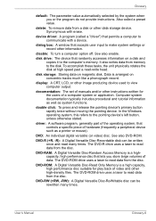
... not provide instructions. disable: To turn a computer option off. documentation: The set of video and other information. The DVD-R drive uses a laser to the pointing device's left button, unless otherwise stated. disk drive: The device that randomly accesses information on a disk and copies it to make system settings or record other high-density files. DVD-ROM: A Digital Versatile Disc-Read Only Memory is arranged on magnetic disk. User's Manual Glossary-6 Also called a "driver") that accepts user input...
... not provide instructions. disable: To turn a computer option off. documentation: The set of video and other information. The DVD-R drive uses a laser to the pointing device's left button, unless otherwise stated. disk drive: The device that randomly accesses information on a disk and copies it to make system settings or record other high-density files. DVD-ROM: A Digital Versatile Disc-Read Only Memory is arranged on magnetic disk. User's Manual Glossary-6 Also called a "driver") that accepts user input...

Users Manual Canada; English
Page 229
... motherboard to the 10th power. I /O: Input/output. keyboard: An input device containing switches that are activated by a communications link that enables any device to interact with leads that transmits a specific code to and from it. Each keystroke activates a switch that extend to 1024 bytes. Memory cache built into character forming segments with any other devices dispersed over a relatively limited area and connected by manually pressing marked keys...
... motherboard to the 10th power. I /O: Input/output. keyboard: An input device containing switches that are activated by a communications link that enables any device to interact with leads that transmits a specific code to and from it. Each keystroke activates a switch that extend to 1024 bytes. Memory cache built into character forming segments with any other devices dispersed over a relatively limited area and connected by manually pressing marked keys...
Detailed Specs for Tecra S11 PTSE3C-0CP002 English
Page 1
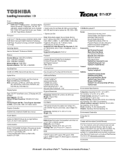
... LCD display with a three (3) year parts and labour Limited International Warranty. max; Preinstalled software is warranted for password and identity management) Computrace™ BIOS support Protect & Fix Spill-Resistant Keyboard Shock Absorbing Design LCD Panel Shock Absorber Hard Disk Drive Protection HDD Shock Absorber HDD Impact Sensor Toshiba Key Component Access Toshiba PC Diagnostic Tool Toshiba PC Health Monitor Connect Diversity Antenna Toshiba ConfigFree® Optimize Toshiba Presentation Button Toshiba Zooming Utility One-touch Resolution Change Toshiba Power Saver Utility...
... LCD display with a three (3) year parts and labour Limited International Warranty. max; Preinstalled software is warranted for password and identity management) Computrace™ BIOS support Protect & Fix Spill-Resistant Keyboard Shock Absorbing Design LCD Panel Shock Absorber Hard Disk Drive Protection HDD Shock Absorber HDD Impact Sensor Toshiba Key Component Access Toshiba PC Diagnostic Tool Toshiba PC Health Monitor Connect Diversity Antenna Toshiba ConfigFree® Optimize Toshiba Presentation Button Toshiba Zooming Utility One-touch Resolution Change Toshiba Power Saver Utility...


