

Owners Manual
Page 4
... for installation, use and servicing. Improper use IMPORTANT SAFETY INSTRUCTIONS CONTENTS 4 CAUTION: PLEASE READ AND OBSERVE ALL WARNINGS AND INSTRUCTIONS GIVEN IN THIS OWNER'S MANUAL AND THOSE MARKED ON THE UNIT. The openings should not be blocked by the user. RETAIN THIS BOOKLET FOR FUTURE REFERENCE. 1. The strong light from battery power, or other instructions. 3. This set has been designed and manufactured to your home, consult...
... for installation, use and servicing. Improper use IMPORTANT SAFETY INSTRUCTIONS CONTENTS 4 CAUTION: PLEASE READ AND OBSERVE ALL WARNINGS AND INSTRUCTIONS GIVEN IN THIS OWNER'S MANUAL AND THOSE MARKED ON THE UNIT. The openings should not be blocked by the user. RETAIN THIS BOOKLET FOR FUTURE REFERENCE. 1. The strong light from battery power, or other instructions. 3. This set has been designed and manufactured to your home, consult...

Owners Manual
Page 7
... be sure the service technician has used replacement parts specified by the manufacturer or have fallen into the product. Continued Adjust only those controls that area. 18. this product yourself as opening or removing covers may cause to service this indicates a need for repair service. Servicing Do not attempt to injury. Safety Check Upon completion of other controls may result in any service or repairs to this product...
... be sure the service technician has used replacement parts specified by the manufacturer or have fallen into the product. Continued Adjust only those controls that area. 18. this product yourself as opening or removing covers may cause to service this indicates a need for repair service. Servicing Do not attempt to injury. Safety Check Upon completion of other controls may result in any service or repairs to this product...
Owners Manual
Page 10
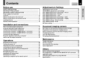
... document imaging camera 55 Picture projection with the document imaging camera 56 Overlaying projection 59 Lock the white balance 60 Correcting illuminated defects 61 Maintenance Trouble indications 62 Air filter cleaning 63 Lens and main unit cleaning 65 Lamp replacement 66 Others Before calling service personal 68 Pin assignment of each part on the remote control 13 Loading batteries 15 Remote control operation 16 Installation and connections Floor-mounted projector placement 17 Projector placement angle adjustment 20 Ceiling-mounted projector placement 21 Connecting...
... document imaging camera 55 Picture projection with the document imaging camera 56 Overlaying projection 59 Lock the white balance 60 Correcting illuminated defects 61 Maintenance Trouble indications 62 Air filter cleaning 63 Lens and main unit cleaning 65 Lamp replacement 66 Others Before calling service personal 68 Pin assignment of each part on the remote control 13 Loading batteries 15 Remote control operation 16 Installation and connections Floor-mounted projector placement 17 Projector placement angle adjustment 20 Ceiling-mounted projector placement 21 Connecting...

Owners Manual
Page 12
... button ENTER button MENU button INPUT button 30 To s e l e c t t h e i n p u t source. KEYSTONE button 35 To correct the keystone distortion of the Computer input automatically. Top side Control panel To adjust volume when the menu is not displayed. 32 AUTO SET button 34 To adjust the image of the picture. ON indicator 28 33 62 LAMP indicator 28 33 62 TEMP indicator 62 FAN indicator 28 33 62 To indicate the status of each part on the main unit (continued) CONTENTS 12 To display the menu screen...
... button ENTER button MENU button INPUT button 30 To s e l e c t t h e i n p u t source. KEYSTONE button 35 To correct the keystone distortion of the Computer input automatically. Top side Control panel To adjust volume when the menu is not displayed. 32 AUTO SET button 34 To adjust the image of the picture. ON indicator 28 33 62 LAMP indicator 28 33 62 TEMP indicator 62 FAN indicator 28 33 62 To indicate the status of each part on the main unit (continued) CONTENTS 12 To display the menu screen...

Owners Manual
Page 14
... button To display the video input 40 image as 42 USB remote control mouse. CALL button 41 To display the information. Laser emission part Remote control transmission part INPUT ON/STANDBY LASER KEYSTONE AUTO SET ON/STANDBY button 28 33 To turn the projector on the remote control CONTENTS 14 Caution - MUTE button 37 To cut off (standby). MANUFACTURED: SEPTEMBER 2000 PLACE OF MANUFACTURE:A IEC60825-1 A1;1997 CT - 9 0 0 5 7 MODEL CONTROL REMOTE 82 TOTOWA RD., WAYNE, NJ 07470, U.S.A. : 1mW MAXIMA) PUISSANCE TOSHIBA...
... button To display the video input 40 image as 42 USB remote control mouse. CALL button 41 To display the information. Laser emission part Remote control transmission part INPUT ON/STANDBY LASER KEYSTONE AUTO SET ON/STANDBY button 28 33 To turn the projector on the remote control CONTENTS 14 Caution - MUTE button 37 To cut off (standby). MANUFACTURED: SEPTEMBER 2000 PLACE OF MANUFACTURE:A IEC60825-1 A1;1997 CT - 9 0 0 5 7 MODEL CONTROL REMOTE 82 TOTOWA RD., WAYNE, NJ 07470, U.S.A. : 1mW MAXIMA) PUISSANCE TOSHIBA...

Owners Manual
Page 18
... The projection size depends on the distance between the lens and the screen (m) 90° a The values are approximations. Adjust the projection size by changing the distances as above. To obtain proper screen projected, place the projector so that the projecting light hits the screen squarely. 2 Determine the screen size projected on a steady, level surface such as a table. Top view Screen Side view Screen CONTENTS 18 90° 90° Installation and connection Point the lens...
... The projection size depends on the distance between the lens and the screen (m) 90° a The values are approximations. Adjust the projection size by changing the distances as above. To obtain proper screen projected, place the projector so that the projecting light hits the screen squarely. 2 Determine the screen size projected on a steady, level surface such as a table. Top view Screen Side view Screen CONTENTS 18 90° 90° Installation and connection Point the lens...

Owners Manual
Page 19
... LAMP ON / STANDBY TEMP FAN Light (Orange) Power cord (Supplied) The three indicators, TEMP, LAMP, and ON, light in green for an adequate time (1 to 2 hours, depending on the projector. • Insert the other end in a wall outlet. Do not perform any operations while the three indicators are not installed properly, the projected picture may condense on the lens or the internal optical section to the standby mode. Installation and connection Floor-mounted projector placement (continued) CONTENTS 19 3 Connect the power cord...
... LAMP ON / STANDBY TEMP FAN Light (Orange) Power cord (Supplied) The three indicators, TEMP, LAMP, and ON, light in green for an adequate time (1 to 2 hours, depending on the projector. • Insert the other end in a wall outlet. Do not perform any operations while the three indicators are not installed properly, the projected picture may condense on the lens or the internal optical section to the standby mode. Installation and connection Floor-mounted projector placement (continued) CONTENTS 19 3 Connect the power cord...

Owners Manual
Page 23
... 2 AUDIO IN VIDEO IN R - Check that are 2 m or shorter is off before connecting the cables. Installation and connection Connecting a computer (COMPUTER IN 2 connector) CONTENTS 23 You can project the picture of analog RGB or digital RGB signal from factory, it is set for use as Analog RGB (2) input. Use of connection cables that the power for the projector and computer is recommended. • The input signal specifications of the DVI port of the projector conform to connect...
... 2 AUDIO IN VIDEO IN R - Check that are 2 m or shorter is off before connecting the cables. Installation and connection Connecting a computer (COMPUTER IN 2 connector) CONTENTS 23 You can project the picture of analog RGB or digital RGB signal from factory, it is set for use as Analog RGB (2) input. Use of connection cables that the power for the projector and computer is recommended. • The input signal specifications of the DVI port of the projector conform to connect...

Owners Manual
Page 28
... time, language selection menu is warming up with procedures 2 and 3 of the next page. Continued Remote control INPUT ON/STANDBY LASER KEYSTONE AUTO SET 1 L-CLICK R-CLICK VOLUME/ADJUST Preparation 1 Install and connect the projector properly. 2 Take off the lens cover. 1 ON/STANDBY Press ON/STANDBY. The projector turns on and the ON, LAMP and FAN ON/STANDBY indicators light in green. (The LAMP indicator blinks while the lamp is displayed after the startup screen disappears. Operations KEYSTONE Projection on the menu screen. 51 • When a projector is used...
... time, language selection menu is warming up with procedures 2 and 3 of the next page. Continued Remote control INPUT ON/STANDBY LASER KEYSTONE AUTO SET 1 L-CLICK R-CLICK VOLUME/ADJUST Preparation 1 Install and connect the projector properly. 2 Take off the lens cover. 1 ON/STANDBY Press ON/STANDBY. The projector turns on and the ON, LAMP and FAN ON/STANDBY indicators light in green. (The LAMP indicator blinks while the lamp is displayed after the startup screen disappears. Operations KEYSTONE Projection on the menu screen. 51 • When a projector is used...
Owners Manual
Page 29
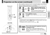
...-select a ENTER language. Operations KEYSTONE Projection on the screen (continued) CONTENTS 29 Remote control INPUT ON/STANDBY LASER KEYSTONE AUTO SET When a projector is used for the first time, the language selection menu, which is to select a language for displaying menus or messages, is turned on next time. • The language can also be selected on the menu screen. 50 INPUT ON LAMP ON / STANDBY TEMP FAN MENU ENTER VOL / ADJ EXIT AUTO SET 2,3 2 4 Turn on the connected equipment and put...
...-select a ENTER language. Operations KEYSTONE Projection on the screen (continued) CONTENTS 29 Remote control INPUT ON/STANDBY LASER KEYSTONE AUTO SET When a projector is used for the first time, the language selection menu, which is to select a language for displaying menus or messages, is turned on next time. • The language can also be selected on the menu screen. 50 INPUT ON LAMP ON / STANDBY TEMP FAN MENU ENTER VOL / ADJ EXIT AUTO SET 2,3 2 4 Turn on the connected equipment and put...

Owners Manual
Page 31
...., refer to DDC2B (Display Data Channel 2B). Turn to the left to enlarge the picture. A still picture is recommended for the computer used. • The projector projects an image by XGA signal (1024 x 768) in full screen. • The image quality of a computer signal except XGA may not be also applied to the computer's manual and description on the software for focusing. It is applied to XGA mode (1024 x 768...
...., refer to DDC2B (Display Data Channel 2B). Turn to the left to enlarge the picture. A still picture is recommended for the computer used. • The projector projects an image by XGA signal (1024 x 768) in full screen. • The image quality of a computer signal except XGA may not be also applied to the computer's manual and description on the software for focusing. It is applied to XGA mode (1024 x 768...

Owners Manual
Page 33
... this time will be turned back on ON/STANDBY the screen and disappears after using the projector for turning the power off and the standby mode is set . We recommend you may not light and the duration life will shorten the lamp's duration life. Turning the power off CONTENTS 33 Operations KEYSTONE Remote control INPUT ON/STANDBY LASER KEYSTONE AUTO SET 1,2 L-CLICK R-CLICK VOLUME/ADJUST MENU ENTER EXIT PIP FREEZE CALL RESIZE MUTE 1,2 INPUT Control panel (Main unit side) ON LAMP ON / STANDBY TEMP FAN 2 Indicators MENU...
... this time will be turned back on ON/STANDBY the screen and disappears after using the projector for turning the power off and the standby mode is set . We recommend you may not light and the duration life will shorten the lamp's duration life. Turning the power off CONTENTS 33 Operations KEYSTONE Remote control INPUT ON/STANDBY LASER KEYSTONE AUTO SET 1,2 L-CLICK R-CLICK VOLUME/ADJUST MENU ENTER EXIT PIP FREEZE CALL RESIZE MUTE 1,2 INPUT Control panel (Main unit side) ON LAMP ON / STANDBY TEMP FAN 2 Indicators MENU...

Owners Manual
Page 41
... "Lamp time" can be reset when the lamp is replaced. • The "Version" is the version of the control program used in the projector and is used for servicing, etc. CONTENTS 41 Remote control INPUT ON/STANDBY LASER KEYSTONE AUTO SET L-CLICK R-CLICK VOLUME/ADJUST CALL MENU ENTER EXIT PIP FREEZE CALL RESIZE MUTE CALL Press CALL. The information display turns off the information display, then turn off when the CALL button is displayed. the...
... "Lamp time" can be reset when the lamp is replaced. • The "Version" is the version of the control program used in the projector and is used for servicing, etc. CONTENTS 41 Remote control INPUT ON/STANDBY LASER KEYSTONE AUTO SET L-CLICK R-CLICK VOLUME/ADJUST CALL MENU ENTER EXIT PIP FREEZE CALL RESIZE MUTE CALL Press CALL. The information display turns off the information display, then turn off when the CALL button is displayed. the...

Owners Manual
Page 45
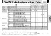
... image flicker. Auto. If the power cord is unplugged or if a power failure occurs while the projector is on, the adjustments or settings are displayed only with its brightness Bright priority or quality (color) priority. Phase ADJ. Yes SET The shutter speed is adjusted automatically To manual adjustment EXEC. To operate GUIDE MENU, refer to 50 Hz - - - - - - Adjusting the Horizontal keystone Yes (common for each RGB signal 71 . • "Keystone" and "Input source setting" can set automatically SET...
... image flicker. Auto. If the power cord is unplugged or if a power failure occurs while the projector is on, the adjustments or settings are displayed only with its brightness Bright priority or quality (color) priority. Phase ADJ. Yes SET The shutter speed is adjusted automatically To manual adjustment EXEC. To operate GUIDE MENU, refer to 50 Hz - - - - - - Adjusting the Horizontal keystone Yes (common for each RGB signal 71 . • "Keystone" and "Input source setting" can set automatically SET...
Owners Manual
Page 46
.... Yes Screen size Full thru Wide SET The picture is converted to XGA (1024 x 768 dot) resolution SET The picture is converted to the camera are not memorized. If the power cord is unplugged or if a power failure occurs while the projector is on, the adjustments or settings are indicated only with the input resolution SET The picture is displayed with a model having the camera. • A part of FULL MENU [Picture] are returned to the factory default setting Yes...
.... Yes Screen size Full thru Wide SET The picture is converted to XGA (1024 x 768 dot) resolution SET The picture is converted to the camera are not memorized. If the power cord is unplugged or if a power failure occurs while the projector is on, the adjustments or settings are indicated only with the input resolution SET The picture is displayed with a model having the camera. • A part of FULL MENU [Picture] are returned to the factory default setting Yes...

Owners Manual
Page 51
... Input source, projection mode, etc. SET The projector continues work even if the no signal is input SET A blue color is on Yes (common for all of the inputs) No signal background Logo Blue background None SET The TOSHIBA logo is displayed when no signal status continues SET The power turns off " is effective. • Each item can set to [Auto] with (+) or (-) COMPUTER IN 1 SET Analog RGB(1) SET Y/PB/PR SET COMPUTER IN 2 SET Analog RGB(2) SET Digital RGB SET VIDEO SET S-VIDEO SET CAMERA SET...
... Input source, projection mode, etc. SET The projector continues work even if the no signal is input SET A blue color is on Yes (common for all of the inputs) No signal background Logo Blue background None SET The TOSHIBA logo is displayed when no signal status continues SET The power turns off " is effective. • Each item can set to [Auto] with (+) or (-) COMPUTER IN 1 SET Analog RGB(1) SET Y/PB/PR SET COMPUTER IN 2 SET Analog RGB(2) SET Digital RGB SET VIDEO SET S-VIDEO SET CAMERA SET...
Owners Manual
Page 53
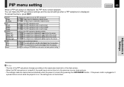
... power is turned off, the audio input source returns to bottom right on , the settings are returned to the factory default setting CONTENTS 53 Adjustments & Settings Notes • The size of the PIP sub-picture changes according to the signal type (resolution) of the PIP sub-picture display position SET :The sub-picture is displayed to upper left on the screen SET :The sub-picture is displayed to upper right on the screen SET :The sub-picture is displayed...
... power is turned off, the audio input source returns to bottom right on , the settings are returned to the factory default setting CONTENTS 53 Adjustments & Settings Notes • The size of the PIP sub-picture changes according to the signal type (resolution) of the PIP sub-picture display position SET :The sub-picture is displayed to upper left on the screen SET :The sub-picture is displayed to upper right on the screen SET :The sub-picture is displayed...

Owners Manual
Page 62
... again. ON LAMP (Lit in red) (Lit in red) TEMP FAN The lamp turns off . * The projector returns to the standby mode in about 2 minutes. Or • Clean the air filter. 63 (Lit in orange) * The icon appears before the power turned off or does not light up or blink. Maintenance KEYSTONE Notes • If abnormality occurs while operating, unplug the power cord. • When reinserting the power cord before the lamp has cooled, please...
... again. ON LAMP (Lit in red) (Lit in red) TEMP FAN The lamp turns off . * The projector returns to the standby mode in about 2 minutes. Or • Clean the air filter. 63 (Lit in orange) * The icon appears before the power turned off or does not light up or blink. Maintenance KEYSTONE Notes • If abnormality occurs while operating, unplug the power cord. • When reinserting the power cord before the lamp has cooled, please...

Owners Manual
Page 68
... the picture. Clean the lens with the INPUT button. Adjust the projecting direction so that it can be selected. Desired input source cannot be • Input is not attached correctly. Attach the cover correctly. Use a proper signal cable. No image appears. • The lens cover is on. • The wrong input is selected. • The muting mode is on . • The power cord is disconnected. • The lamp cover is not set for support service. Focusing is...
... the picture. Clean the lens with the INPUT button. Adjust the projecting direction so that it can be selected. Desired input source cannot be • Input is not attached correctly. Attach the cover correctly. Use a proper signal cable. No image appears. • The lens cover is on. • The wrong input is selected. • The muting mode is on . • The power cord is disconnected. • The lamp cover is not set for support service. Focusing is...

Owners Manual
Page 79
... (RS-232C) Type B Liquid crystal display Projection system Panel size Driving system Picture elements 3-panels transmission 0.9 inches TFT active matrix 786,432 pixels (1024 x 768 dots) (H./V.) x 3 Projection lens Lens Focusing Zooming Zooming lens F=1.7 to 2.1 f=33.6 to 42mm Manual operation Manual operation Document imaging camera (with camera model) Lens F = 3.1, f = 6.4mm Focusing Manual operation Zoom None (adjusted by distance to 35 deg. Specifications CONTENTS 79 Main unit Power consumption TLP780: 300 W (Standby: 20W) TLP781: 310 W (Standby: 20W) Mass TLP780: 4.2 kg...
... (RS-232C) Type B Liquid crystal display Projection system Panel size Driving system Picture elements 3-panels transmission 0.9 inches TFT active matrix 786,432 pixels (1024 x 768 dots) (H./V.) x 3 Projection lens Lens Focusing Zooming Zooming lens F=1.7 to 2.1 f=33.6 to 42mm Manual operation Manual operation Document imaging camera (with camera model) Lens F = 3.1, f = 6.4mm Focusing Manual operation Zoom None (adjusted by distance to 35 deg. Specifications CONTENTS 79 Main unit Power consumption TLP780: 300 W (Standby: 20W) TLP781: 310 W (Standby: 20W) Mass TLP780: 4.2 kg...


