User Guide
Page 224
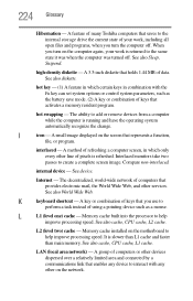
...key or combination of computers or other devices dispersed over a relatively limited area and connected by a communications link that you turn on the motherboard to interact with the Fn key can set system options or control system parameters, such as a mouse. L2 (level two) cache ... - When you use to create a complete screen image. A small image displayed on the network. Compare non-interlaced. A feature of many Toshiba computers that provides electronic mail, the World Wide Web, and other on the screen that activates a memory resident program. LAN (local area network...
...key or combination of computers or other devices dispersed over a relatively limited area and connected by a communications link that you turn on the motherboard to interact with the Fn key can set system options or control system parameters, such as a mouse. L2 (level two) cache ... - When you use to create a complete screen image. A small image displayed on the network. Compare non-interlaced. A feature of many Toshiba computers that provides electronic mail, the World Wide Web, and other on the screen that activates a memory resident program. LAN (local area network...
User Guide
Page 225
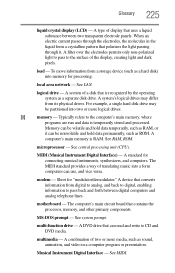
... can be partitioned into two or more media, such as a separate disk drive. M memory - See RAM, ROM. Short for connecting musical instruments, synthesizers, and computers. motherboard - A DVD drive that uses a liquid substance between digital computers and analog telephone lines. logical drive - A system's logical drives may be nonvolatile and hold data permanently...
... can be partitioned into two or more media, such as a separate disk drive. M memory - See RAM, ROM. Short for connecting musical instruments, synthesizers, and computers. motherboard - A DVD drive that uses a liquid substance between digital computers and analog telephone lines. logical drive - A system's logical drives may be nonvolatile and hold data permanently...

Maintenance Manual
Page 9
... Touch Pad Bracket, LED board and Finger Printer Board Error! Installing the Thermal Fan Error! Bookmark not defined. 4.14 Motherboard Error! Bookmark not defined. 4.15 UWB Module Error! Bookmark not defined. Removing the Robson module Error! Bookmark not defined...not defined. 4.16 Robson Module Error! Satellite A350 Series Maintenance Manual [CONFIDENTIAL] ix Bookmark not defined. Bookmark not defined. Bookmark not defined. Bookmark not defined. Bookmark not defined. 4.11 Speakers Error! Installing the Motherboard Error! Removing the UWB module Error! ...
... Touch Pad Bracket, LED board and Finger Printer Board Error! Installing the Thermal Fan Error! Bookmark not defined. 4.14 Motherboard Error! Bookmark not defined. 4.15 UWB Module Error! Bookmark not defined. Removing the Robson module Error! Bookmark not defined...not defined. 4.16 Robson Module Error! Satellite A350 Series Maintenance Manual [CONFIDENTIAL] ix Bookmark not defined. Bookmark not defined. Bookmark not defined. Bookmark not defined. Bookmark not defined. 4.11 Speakers Error! Installing the Motherboard Error! Removing the UWB module Error! ...
Maintenance Manual
Page 11
... defined. Removing screws from the ODD drive...........Error! Bookmark not defined. Bookmark not defined. Bookmark not defined. Error! Removing motherboard from the touch pad bracket .Error! Bookmark not defined. Removing the Robson module Error! Bookmark not defined. Removing the RAM.... Bookmark not defined. Bookmark not defined. Bookmark not defined. Removing the FM Tuner Error! Removing the power board Error! Satellite A350 Series Maintenance Manual [CONFIDENTIAL] xi Removing the modem card Error! Removing five screws from the laptop Error! Bookmark not defined....
... defined. Removing screws from the ODD drive...........Error! Bookmark not defined. Bookmark not defined. Bookmark not defined. Error! Removing motherboard from the touch pad bracket .Error! Bookmark not defined. Removing the Robson module Error! Bookmark not defined. Removing the RAM.... Bookmark not defined. Bookmark not defined. Bookmark not defined. Removing the FM Tuner Error! Removing the power board Error! Satellite A350 Series Maintenance Manual [CONFIDENTIAL] xi Removing the modem card Error! Removing five screws from the laptop Error! Bookmark not defined....

Maintenance Manual
Page 153
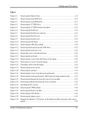
..., LED board and Finger Printer Board... 4-32 4.13 Thermal Fan ...4-35 Removing the Thermal Fan 4-35 Installing the Thermal Fan 4-35 4.14 Motherboard ...4-36 Removing the Motherboard 4-36 Installing the Motherboard 4-36 4.15 UWB Module ...4-38 Removing the UWB module 4-38 Installing the UWB module 4-38 4.16 Robson Module ...4-39 Removing the Robson... and Thermal Module 4-43 Removing CPU and Thermal Module 4-43 Installing CPU and Thermal Module 4-46 4.19 Display Assembly 4-48 Removing the Display Assembly 4-48 Satellite A350 Maintenance Manual 4-iii
..., LED board and Finger Printer Board... 4-32 4.13 Thermal Fan ...4-35 Removing the Thermal Fan 4-35 Installing the Thermal Fan 4-35 4.14 Motherboard ...4-36 Removing the Motherboard 4-36 Installing the Motherboard 4-36 4.15 UWB Module ...4-38 Removing the UWB module 4-38 Installing the UWB module 4-38 4.16 Robson Module ...4-39 Removing the Robson... and Thermal Module 4-43 Removing CPU and Thermal Module 4-43 Installing CPU and Thermal Module 4-46 4.19 Display Assembly 4-48 Removing the Display Assembly 4-48 Satellite A350 Maintenance Manual 4-iii
Maintenance Manual
Page 155
... 4-35 Removing motherboard from logic lower assembly 4-36 Installing the DC-in jack 4-37 Removing the UWB module 4-38 Removing the Robson module 4-39 Removing the VGA Board 4-41 Removing the spring screws 4-41 Reapply the Shinetsu 7726 grease on the thermal module and remove the release papers ...4-42 Satellite A350 Maintenance Manual 4-v
... 4-35 Removing motherboard from logic lower assembly 4-36 Installing the DC-in jack 4-37 Removing the UWB module 4-38 Removing the Robson module 4-39 Removing the VGA Board 4-41 Removing the spring screws 4-41 Reapply the Shinetsu 7726 grease on the thermal module and remove the release papers ...4-42 Satellite A350 Maintenance Manual 4-v
Maintenance Manual
Page 175
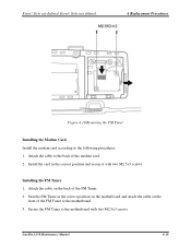
Attach the cable to the motherboard. 3. Style not defined. Error! Seat the FM Tuner in the correct position and secure it with two M2.5x3 screws. Installing the FM Tuner 1. Secure the FM Tuner to the following procedures. 1. Satellite A350 Maintenance Manual 4-19 Error! Style ...not defined. 4 Replacement Procedures Figure 4.10 Removing the FM Tuner Installing the Modem Card Install the modem card according to the motherboard with two M2.5x3 screws. Attach the cable ...
Attach the cable to the motherboard. 3. Style not defined. Error! Seat the FM Tuner in the correct position and secure it with two M2.5x3 screws. Installing the FM Tuner 1. Secure the FM Tuner to the following procedures. 1. Satellite A350 Maintenance Manual 4-19 Error! Style ...not defined. 4 Replacement Procedures Figure 4.10 Removing the FM Tuner Installing the Modem Card Install the modem card according to the motherboard with two M2.5x3 screws. Attach the cable ...

Maintenance Manual
Page 180
Error! Style not defined. Figure 4.14 Removing screws from the motherboard. Lift the keyboard up and detach the cable on the back of the keyboard from the keyboard 4. 4 Replacement Procedures 3. Error! Style not defined. Figure 4.15 Removing the keyboard Satellite A350 Maintenance Manual 4-24 Remove two M2.0x3 screws.
Error! Style not defined. Figure 4.14 Removing screws from the motherboard. Lift the keyboard up and detach the cable on the back of the keyboard from the keyboard 4. 4 Replacement Procedures 3. Error! Style not defined. Figure 4.15 Removing the keyboard Satellite A350 Maintenance Manual 4-24 Remove two M2.0x3 screws.
Maintenance Manual
Page 181
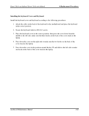
... correct position. 2. Style not defined. 4 Replacement Procedures Installing the keyboard Cover and Keyboard Install the keyboard cover and keyboard according to the motherboard and place the keyboard in the laptop. Secure the keyboard with two M2.0x3 screws. 3. Error! Place the keyboard cover in the correct...key F9 and slide to the left side, make sure the two hooks on the back of the cover stuck in the laptop. 4. Satellite A350 Maintenance Manual 4-25 Error! Attach the cable on the back of the keyboard to the following procedures. 1. Press down from the middle ...
... correct position. 2. Style not defined. 4 Replacement Procedures Installing the keyboard Cover and Keyboard Install the keyboard cover and keyboard according to the motherboard and place the keyboard in the laptop. Secure the keyboard with two M2.0x3 screws. 3. Error! Place the keyboard cover in the correct...key F9 and slide to the left side, make sure the two hooks on the back of the cover stuck in the laptop. 4. Satellite A350 Maintenance Manual 4-25 Error! Attach the cable on the back of the keyboard to the following procedures. 1. Press down from the middle ...

Maintenance Manual
Page 191
...Replacement Procedures 4.13 Thermal Fan Removing the Thermal Fan Remove the thermal fan according to the following procedures. 1. Remove two M2.5x5 screws from the motherboard. 2. Secure the thermal fan with two M2.5x5 screws. 3. Style not defined. Seat the thermal fan in the correct position on the logic lower... thermal fan. 3. Remove the thermal fan from the logic lower assembly Installing the Thermal Fan Install the thermal fan according to the motherboard. Figure 4.23 Removing the thermal fan from the logic lower assembly. Error! Satellite A350 Maintenance Manual 4-35
...Replacement Procedures 4.13 Thermal Fan Removing the Thermal Fan Remove the thermal fan according to the following procedures. 1. Remove two M2.5x5 screws from the motherboard. 2. Secure the thermal fan with two M2.5x5 screws. 3. Style not defined. Seat the thermal fan in the correct position on the logic lower... thermal fan. 3. Remove the thermal fan from the logic lower assembly Installing the Thermal Fan Install the thermal fan according to the motherboard. Figure 4.23 Removing the thermal fan from the logic lower assembly. Error! Satellite A350 Maintenance Manual 4-35

Maintenance Manual
Page 192
Style not defined. 4.14 Motherboard Removing the Motherboard Remove the motherboard according to the following procedures and Figure 4.24. 1. Remove the motherboard from the logic lower assembly as indicated by arrows in Figure 4.24. 2. ...logic lower assembly. Style not defined. Error! Figure 4.24 Removing motherboard from logic lower assembly Installing the Motherboard Install the motherboard according to the following procedures. 1. Seat the motherboard in jack from the logic lower assembly. Satellite A350 Maintenance Manual 4-36 4 Replacement Procedures Error!
Style not defined. 4.14 Motherboard Removing the Motherboard Remove the motherboard according to the following procedures and Figure 4.24. 1. Remove the motherboard from the logic lower assembly as indicated by arrows in Figure 4.24. 2. ...logic lower assembly. Style not defined. Error! Figure 4.24 Removing motherboard from logic lower assembly Installing the Motherboard Install the motherboard according to the following procedures. 1. Seat the motherboard in jack from the logic lower assembly. Satellite A350 Maintenance Manual 4-36 4 Replacement Procedures Error!

Maintenance Manual
Page 193
Put the DC-in jack into the socket and put the DC cables according to the motherboard as indicated by arrows in jack 3. Attach seven cables to the figure 4.25. Style not defined. 4 Replacement Procedures 2. Style not defined. Figure 4.25 Installing the DC-in Figure 4.24. Satellite A350 Maintenance Manual 4-37 Secure one M2.5x4 screw. 4. Error! Error!
Put the DC-in jack into the socket and put the DC cables according to the motherboard as indicated by arrows in jack 3. Attach seven cables to the figure 4.25. Style not defined. 4 Replacement Procedures 2. Style not defined. Figure 4.25 Installing the DC-in Figure 4.24. Satellite A350 Maintenance Manual 4-37 Secure one M2.5x4 screw. 4. Error! Error!

Maintenance Manual
Page 194
...! Error! Press the UWB module down and secure it with two M2.5x3 screws. Style not defined. Remove two M2.5x3 screws from the motherboard. Satellite A350 Maintenance Manual 4-38 Remove the UWB module from the UWB module. 2. Style not defined. 4.15 UWB Module Removing the UWB module Remove the... UWB module according to the following procedures and Figure 4.26. 1. Insert the UWB module into the connector on the motherboard. 2. Figure 4.26 Removing the UWB module Installing the UWB module Install the UWB module according to the following procedures. 1.
...! Error! Press the UWB module down and secure it with two M2.5x3 screws. Style not defined. Remove two M2.5x3 screws from the motherboard. Satellite A350 Maintenance Manual 4-38 Remove the UWB module from the UWB module. 2. Style not defined. 4.15 UWB Module Removing the UWB module Remove the... UWB module according to the following procedures and Figure 4.26. 1. Insert the UWB module into the connector on the motherboard. 2. Figure 4.26 Removing the UWB module Installing the UWB module Install the UWB module according to the following procedures. 1.

Maintenance Manual
Page 195
...Satellite A350 Maintenance Manual 4-39 Remove the Robson module from the Robson module. 2. Style not defined. 4 Replacement Procedures 4.16 Robson Module Removing the Robson module Remove the Robson module according to the following procedures and Figure 4.27. 1. Insert the Robson module into the connector on the motherboard.... 2. Remove two M2.5x3 screws from the motherboard. Style not defined. Error! Press the Robson module down and secure it with two M2.5x4 ...
...Satellite A350 Maintenance Manual 4-39 Remove the Robson module from the Robson module. 2. Style not defined. 4 Replacement Procedures 4.16 Robson Module Removing the Robson module Remove the Robson module according to the following procedures and Figure 4.27. 1. Insert the Robson module into the connector on the motherboard.... 2. Remove two M2.5x3 screws from the motherboard. Style not defined. Error! Press the Robson module down and secure it with two M2.5x4 ...

Maintenance Manual
Page 196
...procedures and Figure 4.28, 4.29. Error! Reapply Shinetsu 7762 grease before starting the repair work. 2. Remove the VGA board from the motherboard. Style not defined. 4.17 VGA Board and VGA Thermal Module (Optional) Removing the VGA Board and VGA Thermal Module Remove the VGA ... one new VGA thermal module, please make sure to let it cool down before installing the VGA thermal module. 4 Replacement Procedures Error! Satellite A350 Maintenance Manual 4-40 Use care when removing and disassembling the unit in mind: 1. Remove three M2.5x4 screws securing the VGA board. ...
...procedures and Figure 4.28, 4.29. Error! Reapply Shinetsu 7762 grease before starting the repair work. 2. Remove the VGA board from the motherboard. Style not defined. 4.17 VGA Board and VGA Thermal Module (Optional) Removing the VGA Board and VGA Thermal Module Remove the VGA ... one new VGA thermal module, please make sure to let it cool down before installing the VGA thermal module. 4 Replacement Procedures Error! Satellite A350 Maintenance Manual 4-40 Use care when removing and disassembling the unit in mind: 1. Remove three M2.5x4 screws securing the VGA board. ...

Maintenance Manual
Page 198
Satellite A350 Maintenance Manual 4-42 Style not defined. Seat the VGA board in Figure 4.30. Installing the VGA Board and VGA Thermal Module Install the VGA board ... one new VGA thermal module, remove the release papers on the thermal module and remove the release papers 2. Seat the VGA thermal module on the motherboard and secure it with three M2.5x4 screws. Reapply Shinetsu 7762 grease on the VGA thermal module as shown in the correct position on the...
Satellite A350 Maintenance Manual 4-42 Style not defined. Seat the VGA board in Figure 4.30. Installing the VGA Board and VGA Thermal Module Install the VGA board ... one new VGA thermal module, remove the release papers on the thermal module and remove the release papers 2. Seat the VGA thermal module on the motherboard and secure it with three M2.5x4 screws. Reapply Shinetsu 7762 grease on the VGA thermal module as shown in the correct position on the...

Maintenance Manual
Page 199
... grease before starting the repair work. 2. Remove four spring screws securing the thermal module to clean the CPU and CPU thermal module. Satellite A350 Maintenance Manual 4-43 Be sure to the following in mind: 1. Style not defined. 4 Replacement Procedures 4.18 CPU and Thermal Module ...cool down before installing the CPU thermal module. The thermal module can become very hot during operation. Remove the thermal module from the motherboard. If you remove the CPU thermal module, please use one new CPU thermal module, please make sure remove the release paper first...
... grease before starting the repair work. 2. Remove four spring screws securing the thermal module to clean the CPU and CPU thermal module. Satellite A350 Maintenance Manual 4-43 Be sure to the following in mind: 1. Style not defined. 4 Replacement Procedures 4.18 CPU and Thermal Module ...cool down before installing the CPU thermal module. The thermal module can become very hot during operation. Remove the thermal module from the motherboard. If you remove the CPU thermal module, please use one new CPU thermal module, please make sure remove the release paper first...
Maintenance Manual
Page 202
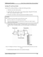
... the relevant screws on the motherboard according to the following in Figure 4.33. Install the thermal module into the correct position in the unlock position. 2. CAUTION: When installing the thermal module, keep the following procedures. 1. Reapply Shinetsu 7762 grease on the CPU thermal module as a guide. 3. Satellite A350 Maintenance Manual 4-46 Rotate the...
... the relevant screws on the motherboard according to the following in Figure 4.33. Install the thermal module into the correct position in the unlock position. 2. CAUTION: When installing the thermal module, keep the following procedures. 1. Reapply Shinetsu 7762 grease on the CPU thermal module as a guide. 3. Satellite A350 Maintenance Manual 4-46 Rotate the...


