User Guide
Page 53
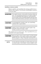
... hot. Installing a memory module with the computer's power on the base of the computer. Before you install or remove a memory module while the computer is in Sleep or Hibernation mode, data will need a small Phillips screwdriver for this model Slot A is the bottom slot. Slot B is the top slot. Avoid touching the cover, the module, and the surrounding area before replacing it must be lost. To avoid damaging the computer's screws, use...
... hot. Installing a memory module with the computer's power on the base of the computer. Before you install or remove a memory module while the computer is in Sleep or Hibernation mode, data will need a small Phillips screwdriver for this model Slot A is the bottom slot. Slot B is the top slot. Avoid touching the cover, the module, and the surrounding area before replacing it must be lost. To avoid damaging the computer's screws, use...
User Guide
Page 58
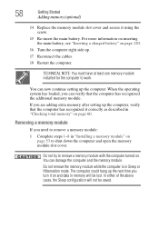
... computer to shut down the computer and open the memory module slot cover. If you need to remove a memory module: 1 Complete steps 1-8 in Sleep or Hibernation mode. You can damage the computer and the memory module. 58 Getting Started Adding memory (optional) 14 Replace the memory module slot cover and secure it correctly as described in memory will not be lost. Do not try to remove a memory module with the computer turned on page 53 to work.
... computer to shut down the computer and open the memory module slot cover. If you need to remove a memory module: 1 Complete steps 1-8 in Sleep or Hibernation mode. You can damage the computer and the memory module. 58 Getting Started Adding memory (optional) 14 Replace the memory module slot cover and secure it correctly as described in memory will not be lost. Do not try to remove a memory module with the computer turned on page 53 to work.

User Guide
Page 60
... heading under Memory (RAM). NOTE From time to work. TECHNICAL NOTE: You must have at least one memory module installed for the computer to time, Windows® will display a pop-up that the module is inserted completely into the socket and lined up . 7 Reconnect the cables. 8 Restart the computer. otherwise, click Cancel. 60 Getting Started Adding memory (optional) 4 Replace the memory module slot cover and secure it using the...
... heading under Memory (RAM). NOTE From time to work. TECHNICAL NOTE: You must have at least one memory module installed for the computer to time, Windows® will display a pop-up that the module is inserted completely into the socket and lined up . 7 Reconnect the cables. 8 Restart the computer. otherwise, click Cancel. 60 Getting Started Adding memory (optional) 4 Replace the memory module slot cover and secure it using the...
User Guide
Page 71
Getting Started 71 Using external display devices NOTE Because the TouchPad is enabled by either double-tapping the TouchPad or clicking the control buttons. To scroll vertically, run your finger along the right edge of the TouchPad. The primary button usually corresponds to determine whether it into place by default. To change the enable/disable TouchPad setting, press Fn + F9. For more information, see "Disabling or enabling the TouchPad™" on the TouchPad™...
Getting Started 71 Using external display devices NOTE Because the TouchPad is enabled by either double-tapping the TouchPad or clicking the control buttons. To scroll vertically, run your finger along the right edge of the TouchPad. The primary button usually corresponds to determine whether it into place by default. To change the enable/disable TouchPad setting, press Fn + F9. For more information, see "Disabling or enabling the TouchPad™" on the TouchPad™...

User Guide
Page 72
... device's power cable to a live electrical outlet. 4 Turn on certain models You cannot connect both the S-video Out port and the HDMI Out port to the same device at the factory to S-video Out. Your computer will automatically detect the external display device and activate a screen with the monitor to see if you first need a larger screen. To do this: 1 Read the directions that came with display options. 5 Select the settings you need to install new software. 2 Connect the monitor's video cable...
... device's power cable to a live electrical outlet. 4 Turn on certain models You cannot connect both the S-video Out port and the HDMI Out port to the same device at the factory to S-video Out. Your computer will automatically detect the external display device and activate a screen with the monitor to see if you first need a larger screen. To do this: 1 Read the directions that came with display options. 5 Select the settings you need to install new software. 2 Connect the monitor's video cable...
User Guide
Page 73
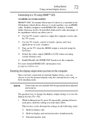
... HDMI cable. Getting Started 73 Using external display devices Connecting to a TV using the Fn+F5 key. ❖ Switch the video output (HDMI or LCD) when executing certain desktop icons. ❖ Enable/Disable the HDMI-CEC function on the computer Once you have connected an external display device, you want takes effect. Directing the display output when you turn on the computer. NOTE Some modes are only available with HDMI-CEC include a Toshiba utility (that may need to be installed...
... HDMI cable. Getting Started 73 Using external display devices Connecting to a TV using the Fn+F5 key. ❖ Switch the video output (HDMI or LCD) when executing certain desktop icons. ❖ Enable/Disable the HDMI-CEC function on the computer Once you have connected an external display device, you want takes effect. Directing the display output when you turn on the computer. NOTE Some modes are only available with HDMI-CEC include a Toshiba utility (that may need to be installed...
User Guide
Page 155
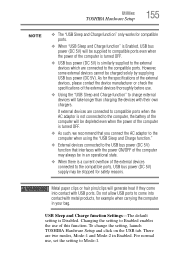
... function. USB Sleep and Charge function Settings-The default setting is similarly supplied to the external devices which are two modes, Mode-1 and Mode-2 in your bag. However, some external devices cannot be supplied to compatible ports even when the power of the computer is turned OFF. ❖ USB bus power (DC 5V) is Disabled. To change the setting, launch TOSHIBA Hardware Setup and click on the USB tab. For normal use, set the setting to Enabled enables the use . ❖ Using the "USB Sleep and Charge function...
... function. USB Sleep and Charge function Settings-The default setting is similarly supplied to the external devices which are two modes, Mode-1 and Mode-2 in your bag. However, some external devices cannot be supplied to compatible ports even when the power of the computer is turned OFF. ❖ USB bus power (DC 5V) is Disabled. To change the setting, launch TOSHIBA Hardware Setup and click on the USB tab. For normal use, set the setting to Enabled enables the use . ❖ Using the "USB Sleep and Charge function...
User Guide
Page 156
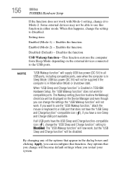
..."USB Sleep and Charge function" will not be displayed on the external devices connected to use this happens, change the settings the "USB Wakeup function" will supply USB bus power (DC 5V) to Disabled. If all USB ports, including compatible ports, even when the computer is in either mode. By changing any of the options that function. Enables the function Disabled (Default) -- Enables the function Enabled (Mode-2) -- 156 Utilities TOSHIBA Hardware Setup If the function does not work for compatible ports. The "USB Wakeup function" will now work . USB bus power...
..."USB Sleep and Charge function" will not be displayed on the external devices connected to use this happens, change the settings the "USB Wakeup function" will supply USB bus power (DC 5V) to Disabled. If all USB ports, including compatible ports, even when the computer is in either mode. By changing any of the options that function. Enables the function Disabled (Default) -- Enables the function Enabled (Mode-2) -- 156 Utilities TOSHIBA Hardware Setup If the function does not work for compatible ports. The "USB Wakeup function" will now work . USB bus power...
User Guide
Page 172
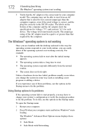
... must match exactly. To do this, use the options in the Startup menu to your computer model. The voltage level must be able to start from the normal routine. ❖ The screen does not look right. The Windows® Advanced Boot Options menu displays these problems, use the options in some way such as installing a new program or adding a device. To open the Startup menu: 1 Restart your computer. 2 Press F8 when...
... must match exactly. To do this, use the options in the Startup menu to your computer model. The voltage level must be able to start from the normal routine. ❖ The screen does not look right. The Windows® Advanced Boot Options menu displays these problems, use the options in some way such as installing a new program or adding a device. To open the Startup menu: 1 Restart your computer. 2 Press F8 when...

User Guide
Page 176
... error recurs, remove the memory module entirely and check for updating the driver or rolling back the driver in the dialog box vary from one memory module installed for these first: 1 Click Start, and then click the arrow next to the Lock button in the lower-right part of the Start menu. Memory problems Incorrectly connected or faulty memory modules may be hardware or even software related. For more information about Device Manager, refer to Windows...
... error recurs, remove the memory module entirely and check for updating the driver or rolling back the driver in the dialog box vary from one memory module installed for these first: 1 Click Start, and then click the arrow next to the Lock button in the lower-right part of the Start menu. Memory problems Incorrectly connected or faulty memory modules may be hardware or even software related. For more information about Device Manager, refer to Windows...

User Guide
Page 179
... key. Display problems Here are using the built-in while the computer was turned on. If you have plugged the external keyboard in screen, make sure the display priority is not set for an external monitor. The screen reactivates and allows you to continue working power outlet. ❖ Check that the cable connecting the external monitor to activate the screen. Display Auto Off may have gone into a working . If no password is registered, press any key, type...
... key. Display problems Here are using the built-in while the computer was turned on. If you have plugged the external keyboard in screen, make sure the display priority is not set for an external monitor. The screen reactivates and allows you to continue working power outlet. ❖ Check that the cable connecting the external monitor to activate the screen. Display Auto Off may have gone into a working . If no password is registered, press any key, type...
User Guide
Page 224
... device to the internal storage drive the current state of computers that you turn on the network. A feature of data. hot swapping - Compare non-interlaced. I icon - See device. K keyboard shortcut - L2 (level two) cache - Memory cache installed on the screen that holds 1.44 MB of many Toshiba computers that activates a memory resident program. high-density diskette - hot key - (1) A feature in combination with the Fn key can set system options...
... device to the internal storage drive the current state of computers that you turn on the network. A feature of data. hot swapping - Compare non-interlaced. I icon - See device. K keyboard shortcut - L2 (level two) cache - Memory cache installed on the screen that holds 1.44 MB of many Toshiba computers that activates a memory resident program. high-density diskette - hot key - (1) A feature in combination with the Fn key can set system options...
User Guide
Page 231
... missing files/trouble accessing a drive 181 running slow 182 diskette drive cannot insert a diskette 182 cannot read a diskette 182 connecting 76 external, connecting 76 display does not look normal/flickers 180 external monitor not working 180 display device external 71 display output settings 73 display panel opening 50 display problems screen is blank 179 display, external adjusting 74 disposal information 28 disposing of used batteries 123 double-click 71 DVD using 101 DVD player general problems 190 E eject button optical drive 102 eject...
... missing files/trouble accessing a drive 181 running slow 182 diskette drive cannot insert a diskette 182 cannot read a diskette 182 connecting 76 external, connecting 76 display does not look normal/flickers 180 external monitor not working 180 display device external 71 display output settings 73 display panel opening 50 display problems screen is blank 179 display, external adjusting 74 disposal information 28 disposing of used batteries 123 double-click 71 DVD using 101 DVD player general problems 190 E eject button optical drive 102 eject...
User Guide
Page 232
... 175 headphones using 134 Help and Support Windows® operating system 174 Hibernation mode 78 configuring 82 hot key 208 starting again from 84 hot key disabling or enabling TouchPad™ 212 display brightness 210 Hibernation mode 208 keyboard overlays 214 Lock (Instant security) 205 Output (Display switch) 209 power plan 206 Sleep mode 207 volume mute 204 Zoom (Display resolution) 213 zooming in 214 zooming out 214 Hot Key Cards 200 Hot key functions 204 hot key power plan 117 http 131 I i.LINK port fast...
... 175 headphones using 134 Help and Support Windows® operating system 174 Hibernation mode 78 configuring 82 hot key 208 starting again from 84 hot key disabling or enabling TouchPad™ 212 display brightness 210 Hibernation mode 208 keyboard overlays 214 Lock (Instant security) 205 Output (Display switch) 209 power plan 206 Sleep mode 207 volume mute 204 Zoom (Display resolution) 213 zooming in 214 zooming out 214 Hot Key Cards 200 Hot key functions 204 hot key power plan 117 http 131 I i.LINK port fast...
User Guide
Page 233
... Internet Service Providers ISPs 131 J jack RJ-11 130 K keyboard character keys 92 function keys 93 hot keys 214 not working 170 overlay keys 94 special Windows® keys 93 troubleshooting 178 unexpected characters 178 using 92 keyboard, external 74 keyboard, full-size 92 L light AC power 47 drive in-use indicator 102 lock computer, using 88 M main battery changing 118 installing 118, 120 removing 118 safety precautions 121 manual eject hole optical drive 102 memory adding 52 problem solving 176 removing memory module slot cover 55 memory module installation 53 installing...
... Internet Service Providers ISPs 131 J jack RJ-11 130 K keyboard character keys 92 function keys 93 hot keys 214 not working 170 overlay keys 94 special Windows® keys 93 troubleshooting 178 unexpected characters 178 using 92 keyboard, external 74 keyboard, full-size 92 L light AC power 47 drive in-use indicator 102 lock computer, using 88 M main battery changing 118 installing 118, 120 removing 118 safety precautions 121 manual eject hole optical drive 102 memory adding 52 problem solving 176 removing memory module slot cover 55 memory module installation 53 installing...

User Guide
Page 234
... positioning 104 optical drive drive in-use indicator light 102 eject button 102 manual eject hole 102 problems 183 removing disc 106, 107 troubleshooting 183 using 101 optical media recording 106 other documentation 40 overlay keys 94 P password deleting a supervisor 148 disabling a user 149 setting a user 148 supervisor set up 147 types 146 passwords instant, using 146 setting 146 port RGB 71 power computer will not start 169 connecting cable to AC adaptor 48 cord/cable 48 cord/cable connectors 215...
... positioning 104 optical drive drive in-use indicator light 102 eject button 102 manual eject hole 102 problems 183 removing disc 106, 107 troubleshooting 183 using 101 optical media recording 106 other documentation 40 overlay keys 94 P password deleting a supervisor 148 disabling a user 149 setting a user 148 supervisor set up 147 types 146 passwords instant, using 146 setting 146 port RGB 71 power computer will not start 169 connecting cable to AC adaptor 48 cord/cable 48 cord/cable connectors 215...

Maintenance Manual
Page 3
... be sure to use only the same model battery or an equivalent battery recommended by Toshiba. Toshiba requires service technicians and authorized dealers or service providers to ensure the following safety precautions are intended to help service technicians isolate faulty Field Replaceable Units (FRUs) and replace them in death or serious bodily injury if the safety instruction is not observed. Satellite A350 Series Maintenance Manual [CONFIDENTIAL] iii...
... be sure to use only the same model battery or an equivalent battery recommended by Toshiba. Toshiba requires service technicians and authorized dealers or service providers to ensure the following safety precautions are intended to help service technicians isolate faulty Field Replaceable Units (FRUs) and replace them in death or serious bodily injury if the safety instruction is not observed. Satellite A350 Series Maintenance Manual [CONFIDENTIAL] iii...

Maintenance Manual
Page 157
Error! Style not defined. How to disassemble the laptop and replace Field Replaceable Units (FRUs). Style not defined. 4 Replacement Procedures 4.1 General This chapter explains how to use the chart (two examples): • For removing the Motheroard: First, remove parts from 4.8 Keyboard Cover & Keyboard, 4.9 Logic Upper Assembly, 4.13 Thermal Fan. • For removing the LCD Module: First, remove LCD Bezel Assembly, then remove the LCD module and the Inverter Board. To replace the FRUs, first identify...
Error! Style not defined. How to disassemble the laptop and replace Field Replaceable Units (FRUs). Style not defined. 4 Replacement Procedures 4.1 General This chapter explains how to use the chart (two examples): • For removing the Motheroard: First, remove parts from 4.8 Keyboard Cover & Keyboard, 4.9 Logic Upper Assembly, 4.13 Thermal Fan. • For removing the LCD Module: First, remove LCD Bezel Assembly, then remove the LCD module and the Inverter Board. To replace the FRUs, first identify...

Maintenance Manual
Page 161
... them out. Error! Style not defined. Satellite A350 Maintenance Manual 4-5 Hurried reassembly can be installed or removed by raising the pressure plate up to reassemble the laptop after you have disassembled the laptop and fixed the component that the FRUs are used for all the required screws are secure. Style not defined. 4 Replacement Procedures Disassembly Procedures The cable connectors come in these two basic types: ‰...
... them out. Error! Style not defined. Satellite A350 Maintenance Manual 4-5 Hurried reassembly can be installed or removed by raising the pressure plate up to reassemble the laptop after you have disassembled the laptop and fixed the component that the FRUs are used for all the required screws are secure. Style not defined. 4 Replacement Procedures Disassembly Procedures The cable connectors come in these two basic types: ‰...
Maintenance Manual
Page 179
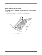
Figure 4.13 Removing the keyboard cover Satellite A350 Maintenance Manual 4-23 Use a flat head screwdriver to the following procedures and Figure 4.13, 4.14, 4.15. 1. Error! Remove the keyboard cover. Error! Style not defined. Style not defined. 4 Replacement Procedures 4.8 Keyboard Cover and Keyboard Removing the Keyboard Cover and Keyboard Remove the Keyboard Cover and Keyboard according to lift the keyboard cover from the laptop. 2.
Figure 4.13 Removing the keyboard cover Satellite A350 Maintenance Manual 4-23 Use a flat head screwdriver to the following procedures and Figure 4.13, 4.14, 4.15. 1. Error! Remove the keyboard cover. Error! Style not defined. Style not defined. 4 Replacement Procedures 4.8 Keyboard Cover and Keyboard Removing the Keyboard Cover and Keyboard Remove the Keyboard Cover and Keyboard according to lift the keyboard cover from the laptop. 2.


