
Maintenance Manual
Page 8
Chapter 4 Replacement Procedures 4.1 Overview...4-1 4.2 Battery pack ...4-8 4.3 PC card...4-10 4.4 Memory module B 4-11 4.5 HDD...4-13 4.6 Keyboard...4-17 4.7 Memory module A 4-21 4.8 Cover assembly and Base assembly 4-23 4.9 Base latch ...4-... 4.15 3G card...4-44 4.16 LAN jack...4-46 4.17 MJ board ...4-47 4.18 RTC battery...4-50 4.19 RGB board ...4-51 4.20 Sensor board...4-53 4.21 Fan/Heat sink ...4-54 4.22 PC card slot ...4-57 4.23 System board and LCD cover assembly 4-58 4.24 LCD mask ...4-61 4.25 LCD unit ...4-63 4.26...
Chapter 4 Replacement Procedures 4.1 Overview...4-1 4.2 Battery pack ...4-8 4.3 PC card...4-10 4.4 Memory module B 4-11 4.5 HDD...4-13 4.6 Keyboard...4-17 4.7 Memory module A 4-21 4.8 Cover assembly and Base assembly 4-23 4.9 Base latch ...4-... 4.15 3G card...4-44 4.16 LAN jack...4-46 4.17 MJ board ...4-47 4.18 RTC battery...4-50 4.19 RGB board ...4-51 4.20 Sensor board...4-53 4.21 Fan/Heat sink ...4-54 4.22 PC card slot ...4-57 4.23 System board and LCD cover assembly 4-58 4.24 LCD mask ...4-61 4.25 LCD unit ...4-63 4.26...
Maintenance Manual
Page 213
4 Replacement Procedures Chapter 4 Contents 4.1 General...4-1 4.2 Battery pack ...4-8 4.3 PC card...4-10 4.4 SD memory card ...4-11 4.5 Memory module...4-12 4.6 Base cover assembly 4-15 4.7 PC card slot ...4-18 4.8 Battery lock/Battery latch 4-20 4.9 Wireless LAN card 4-21 4.10 CPU fan assembly...4-23 4.11 RTC battery...4-26 4.12 DC-IN jack...4-28 4.13 Bluetooth module...4-29 .../Fingerprint sensor board 4-54 4.22 Keyboard...4-57 4.23 LCD unit ...4-59 4.24 Wireless LAN antenna/Bluetooth antenna 4-62 4.25 Hinge...4-64 PORTÉGÉ R500 Maintenance Manual (960-634) [CONFIDENTIAL] 4-iii
4 Replacement Procedures Chapter 4 Contents 4.1 General...4-1 4.2 Battery pack ...4-8 4.3 PC card...4-10 4.4 SD memory card ...4-11 4.5 Memory module...4-12 4.6 Base cover assembly 4-15 4.7 PC card slot ...4-18 4.8 Battery lock/Battery latch 4-20 4.9 Wireless LAN card 4-21 4.10 CPU fan assembly...4-23 4.11 RTC battery...4-26 4.12 DC-IN jack...4-28 4.13 Bluetooth module...4-29 .../Fingerprint sensor board 4-54 4.22 Keyboard...4-57 4.23 LCD unit ...4-59 4.24 Wireless LAN antenna/Bluetooth antenna 4-62 4.25 Hinge...4-64 PORTÉGÉ R500 Maintenance Manual (960-634) [CONFIDENTIAL] 4-iii
Maintenance Manual
Page 214
4 Replacement Procedures Figures Figure 4-1 Figure 4-2 Figure 4-3 Figure 4-4 Figure 4-5 Figure 4-6 Figure 4-7 Figure 4-8 Figure 4-9 Figure 4-10 Figure 4-11 Figure 4-12...Removing the PC card slot 4-18 Removing the battery lock/battery latch 4-20 Removing the wireless LAN card 4-21 Removing the CPU Fan assembly 4-23 Applying new grease 4-24 Removing the RTC battery 4-26 Removing the DC-IN jack 4-28 Removing the Bluetooth module... system board (2 4-46 Removing the speaker 4-48 Removing the display portion (1 4-50 4-iv [CONFIDENTIAL] PORTÉGÉ R500 Maintenance Manual (960-634)
4 Replacement Procedures Figures Figure 4-1 Figure 4-2 Figure 4-3 Figure 4-4 Figure 4-5 Figure 4-6 Figure 4-7 Figure 4-8 Figure 4-9 Figure 4-10 Figure 4-11 Figure 4-12...Removing the PC card slot 4-18 Removing the battery lock/battery latch 4-20 Removing the wireless LAN card 4-21 Removing the CPU Fan assembly 4-23 Applying new grease 4-24 Removing the RTC battery 4-26 Removing the DC-IN jack 4-28 Removing the Bluetooth module... system board (2 4-46 Removing the speaker 4-48 Removing the display portion (1 4-50 4-iv [CONFIDENTIAL] PORTÉGÉ R500 Maintenance Manual (960-634)
Maintenance Manual
Page 239
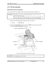
...R500 Maintenance Manual (960-634) [CONFIDENTIAL] 4-23 Be sure to the fan. When you remove the CPU fan assembly, wipe the grease off of the bottom of the heat sink and top of the CPU. Disconnect the fan cable from the connector CN8771 on the system board and remove the CPU fan...pressure to let it cool before starting repair work. Apply new grease when installing. 1. 4.10 CPU fan assembly 4 Replacement Procedures 4.10 CPU fan assembly Removing the CPU fan assembly To remove the CPU fan assembly, follow the steps below and refer to Figure 4-12. CAUTION: The CPU can become very ...
...R500 Maintenance Manual (960-634) [CONFIDENTIAL] 4-23 Be sure to the fan. When you remove the CPU fan assembly, wipe the grease off of the bottom of the heat sink and top of the CPU. Disconnect the fan cable from the connector CN8771 on the system board and remove the CPU fan...pressure to let it cool before starting repair work. Apply new grease when installing. 1. 4.10 CPU fan assembly 4 Replacement Procedures 4.10 CPU fan assembly Removing the CPU fan assembly To remove the CPU fan assembly, follow the steps below and refer to Figure 4-12. CAUTION: The CPU can become very ...
Maintenance Manual
Page 240
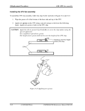
4 Replacement Procedures 4.10 CPU fan assembly Installing the CPU fan assembly To install the CPU fan assembly, follow the steps below and refer to spread new grease. Use a spatula to Figure 4-12 and 4-13. 1. NG Chip Grease is over the height ... new grease shall not be over the height of the CPU chip. CPU OK Chip Figure 4-13 Applying new grease 4-24 [CONFIDENTIAL] PORTÉGÉ R500 Maintenance Manual (960-634) Apply new grease evenly on the CPU using the special applicator. CAUTION: Apply the silicon grease 0.2g 0.1mL Max to cover...
4 Replacement Procedures 4.10 CPU fan assembly Installing the CPU fan assembly To install the CPU fan assembly, follow the steps below and refer to spread new grease. Use a spatula to Figure 4-12 and 4-13. 1. NG Chip Grease is over the height ... new grease shall not be over the height of the CPU chip. CPU OK Chip Figure 4-13 Applying new grease 4-24 [CONFIDENTIAL] PORTÉGÉ R500 Maintenance Manual (960-634) Apply new grease evenly on the CPU using the special applicator. CAUTION: Apply the silicon grease 0.2g 0.1mL Max to cover...
Maintenance Manual
Page 241
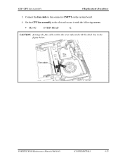
4.10 CPU fan assembly 4 Replacement Procedures 3. Set the CPU fan assembly to the connector CN8771 on the system board. 4. Connect the fan cable to the slot and secure it with the following screws. • M2×6C S-THIN HEAD ×2 CAUTION: Arrange the fan cable within the area indicated with the thick line in the figure below. Fan cable PORTÉGÉ R500 Maintenance Manual (960-634) [CONFIDENTIAL] 4-25
4.10 CPU fan assembly 4 Replacement Procedures 3. Set the CPU fan assembly to the connector CN8771 on the system board. 4. Connect the fan cable to the slot and secure it with the following screws. • M2×6C S-THIN HEAD ×2 CAUTION: Arrange the fan cable within the area indicated with the thick line in the figure below. Fan cable PORTÉGÉ R500 Maintenance Manual (960-634) [CONFIDENTIAL] 4-25


